Motorola MW 800 Series Vehicle Installation Manual
Hide thumbs
Also See for MW 800 Series:
- Owner's manual (29 pages) ,
- Owner's manual (33 pages) ,
- Manual (46 pages)

Related Manuals for Motorola MW 800 Series


Summary of Contents for Motorola MW 800 Series
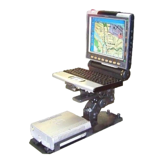
- Page 1 Vehicle Installation Guide Mobile Workstation MW 800 Series Models: F5206, F5207 & F5217 6802967C20-E @6802967C20@...
- Page 3 One (1) Year from the date of shipment. Motorola, at its option, will at no charge either repair the Product (with new or reconditioned parts), replace it with the same or equivalent Product (using new or reconditioned Product), or refund the purchase price of the Product during the warranty period provided purchaser notifies Motorola according to the terms of this warranty.
- Page 4 VI. PATENT AND SOFTWARE PROVISIONS: Motorola will defend, at its own expense, any suit brought against the end user purchaser to the extent that it is based on a claim that the Product or its parts infringe a United States patent, and Motorola will pay those costs and damages finally awarded against the end user purchaser in any such suit which are attributable to any such claim, but such defense and payments are conditioned on the following: A) that Motorola will be notified promptly in writing by such purchaser of any notice of such claim;...
-
Page 5: Table Of Contents
MW 800 Keyboard ....................13 MW 800 Display ....................14 MW 800 CPU Box ....................15 MW 800 GPS Antenna................... 16 Government & Enterprise Mobility Solutions 1301 E. Algonquin Road, Schaumburg, IL 60196 6802967C20-E Copyright © 2005 Motorola All Rights Reserved. March, 2005... - Page 6 MW 800 Vehicle Installation Guide Interconnection of the MW 800 CPU Box ............17 ..........................19 W-WAN Antenna Connection ................19 W-LAN Radio (802.11b) Connection ..............19 GPS Connection ..................... 19 Video In Connection....................19 Display Connections....................19 USB Connections ....................20 Firewire Connection ....................
-
Page 7: References
References You may need to refer to the documents listed below for further information. These documents can be obtained from the following source: Motorola Americas Parts Division Motorola Literature Distribution Center Motorola Centralized Customer Service 2290 Hammond Drive 1313 E. Algonquin Road... - Page 8 MW 800 Vehicle Installation Guide This page Intentionally left blank...
-
Page 9: Using This Manual
• Consult the dealer or an experienced radio/TV technician for help. For detailed product safety and RF exposure for mobile stations with two-way radios installed in vehicles, refer to Electromagnetic Emission (EME) safety leaflet, Motorola publication Number 68P02967C16. -
Page 10: Fcc Grant Of Equipment Authorization
MW 800 Vehicle Installation Guide FCC Grant Of Equipment Authorization Table 1 FCC Grant of Equipment Authorization Radio Network FCC ID Freq Band (MHz) Power DataTAC Private DataTAC PQS-BM28001 806-825 1.8W GPRS IHDT6AC1 900/1900 or 925/1800 2W/1W iO1000 iDEN AZ489FT5796 806-821 0.6W Wireless LAN... -
Page 11: Introduction
Introduction This section lists the features of the Mobile Workstation 800 (MW 800) vehicle mount. This section refers to a specific models of Motorola or SDI manufactured mounts. Please note that the MW 800 may also be installed with any other models of Motorola or SDI manufactured Note mounts. - Page 12 (see Figure 8 and Figure 9). The CPU box mount can be installed in any other suitable location inside the vehicle. Motorola recommends the use of the CPU mount. Failure to do so may result in hard drive damage due to vibration.
-
Page 13: Installation
Installation This section describes the tools and equipment, planning requirements, and product inspections necessary for a smooth installation of the Mobile Workstation 800 (MW 800). Proper planning will help to ensure that the installation is completed without difficulty and that no damage occurs to the units or the vehicle. The MW 800 is a reliable product when installed correctly. -
Page 14: Mw 800 Mounting Location
MW 800 Vehicle Installation Guide • Environmental considerations • Electrical guidelines • Liquid Propane (LP) gas warning • Usability by driver/operator • Vehicle vendor instructions • Local vehicle authority regulations/design rules When installing the MW 800, make sure that the CPU box mount or any support is tightly anchored to the vehicle structure. -
Page 15: Air Bag Considerations
Installation Air Bag Considerations Provided for your reference are several air bag deployment zone templates from automobiles used in public safety roles (Figure 3, Figure 4 and Figure 5). It is very important to obtain the official documents of the automobile to ensure the safe installation. Copyright ©... - Page 16 MW 800 Vehicle Installation Guide Figure 5 Air Bag Deployment Zones - Lumina...
-
Page 17: Environmental Considerations
If a power cut-off device is used in order to conserve vehicle battery life, please consult a qualified Motorola authorized installation shop or contact the Motorola system support center for assistance. Cables longer than 10 ft. (3.05 m) should be routed through special UL listed conduit/duct for electrical cables. -
Page 18: Installation Procedure
MW 800 Vehicle Installation Guide Installation Procedure Mounting the MW 800 Perform the following steps to install the MW 800: Step 1. Determine the proper mounting location. Step 2. Remove the hardware bag from the shipping container. Step 3. Ensure that the pedestal is securely bolted together. Step 4. -
Page 19: Mw 800 Keyboard
Installation Step 5. Place the mount assembly with the CPU Box mount (if desired) in the vehicle and use it for marking the location of the base plate or the hump plate on the vehicle transmission hump. If no hump exists, place the pedestal or SDI tunnel plate between the driver and the passenger seats for marking the location. -
Page 20: Mw 800 Display
MW 800 Vehicle Installation Guide MW 800 Display The MW 800 display is attached to the display mount by Phillips screws (M4), supplied in the display shipping carton. The Display Signal Cable is routed from the CPU box, through the mount, and connected to the lower back side of the display. Use caution when assembling the cable to the display, to prevent damage to the display or the cable. -
Page 21: Mw 800 Cpu Box
Installation MW 800 CPU Box The MW 800 CPU box should be mounted so that the cables from the keyboard(s), display(s), power system and peripherals can be attached. The limiting factor is the 17 feet length of the display signal cable. When attached to the display, this cable is routed down through the pedestal to the CPU box. -
Page 22: Mw 800 Gps Antenna
MW 800 Vehicle Installation Guide The CPU box can be mounted anywhere in the passenger compartment of the vehicle that provides adequate ventilation (see Figure 2). It is recommended that the CPU box be mounted in a place where the PC Card slot can be easily accessed. -
Page 23: Interconnection Of The Mw 800 Cpu Box
Installation Interconnection of the MW 800 CPU Box This section refers to MW 800 with display, keyboard and peripherals. Figure 13 and Figure 14 show an optional connection layout for the MW 800, and Figure 16 shows the display connections. Note that any USB 1.1(model F5206) or USB 2 (model F5207), RS-232, Firewire or Bluetooth based devices may be used. - Page 24 MW 800 Vehicle Installation Guide Vehicle Power System 15 A Fuse GPS Antenna 15 A Fuse Wireless LAN 15 A Antenna Fuse Bluetooth GPRS Antenna Camera DC Power Cable Ignition Sense Display Display 1 Signal Cable Input AIN SWITCH 13.8V IDEO IN ERIAL Digital...
-
Page 25: W-Wan Antenna Connection
Standard Composite video input (CVBS). The MW 800 is equipped with a BNC type connector to which a video camera can be connected. A BNC to RCA adapter 5802810C07 is also available from Motorola, if required. Display Connections Standard Interfaces Red Green Blue (RGB) connection for two display units (F5206 &... -
Page 26: Usb Connections
PWR Connection The MW 800 is equipped with two Motorola DC power cables and fuses, one for the CPU box and the second for the display. To connect power to the MW 800 units perform the following steps: Step 1. -
Page 27: Aux Connection
Installation AUX Connection This port provides ignition sense connection to the MW 800. This port can also be used to supply 5VDC (2A max for F5206 1A for F5207) and car battery voltage out (2A max for F5206 1A for F5207). The AUX port provides two digital TTL level one bit inputs and two one bit outputs. -
Page 28: Turn-On Modes
MW 800 Vehicle Installation Guide Turn-on Modes The MW 800 has four optional turn-on modes using the ignition key and the Power buttons of the display or CPU box. Setting an optional turn-on mode is performed by software application. Using the Power Button or Ignition Key to Start the MW 800 This mode is the default workstation setting. -
Page 29: Turning On The Mw 800
Caution Replacing Power Cable Fuse (Vehicle Power) Remove the fuse (15A) from the fuse holder located on the Motorola DC cable and replace it with a new one of the same type and value (part no. 6580283E06). -
Page 30: Storage
MW 800 Vehicle Installation Guide Storage Important Note: Maximum storage period in shipping package is six months. To refresh storage, assemble the workstation and run Disk Defragmenter (Go to: Start->Programs- >Accessories->System Tools->Disk Defragmenter) -
Page 31: Receptacles
Receptacles Receptacles Table 2 SERIAL Connection Pin No. Signal DTR1 2_GND DSR1 STS1 CTS1 Table 3 AUX Connection - Model F5206 Pin No. Signal Description IGNITION_MODE 12V DC Ignition sense input from ignition key INPUT1 Digital input TTL (5V) level INPUT2 Digital input TTL level OUTPUT1... - Page 32 MW 800 Vehicle Installation Guide Table 3 AUX Connection - Model F5206 Pin No. Signal Description MONITOR_MODE Service input signal Output power. Maximum 2 Amps. Output is automatically disconnected when CPU box temperature is above operating range Table 4 AUX Connection - Model F5207 Pin No.
- Page 33 Receptacles Pin No. Signal Description GPI1 General purpose digital input number 1, TTL level (5V) GPO0 General purpose digital output number 0, TTL level GPO1 General purpose digital output number 1, TTL level I/O data for “one wire” programming of the HC08 controller in the CPU box DSC-EN Aux Radio Enable input signal for GPRS radio...
- Page 34 MW 800 Vehicle Installation Guide Pin No. Signal Description Ground Ground Ground V12-OUT Output power. Maximum 1 Amps. Output inhibits when CPU box temperature is above operating range. The output power corresponds to the power that operates the CPU box V12-OUT Identical to pin 14 GPI0...
- Page 35 Receptacles Table 7 IEEE 1394a (Firewire) Pin No. Signal TPB0- TPB0+ TPA0- TPA0+ Table 8 LAN Connection Pin No. Signal TX_ENG CTS1 TX_POS RX_ENG RX_PDS Table 9 DISPLAY 1 Connection Pin No. Signal Green Blue VSYNC USB(+) USB(-) SP4-L1 SP4-R1 MIC_POS...
- Page 36 MW 800 Vehicle Installation Guide Table 9 DISPLAY 1 Connection Pin No. Signal USB-5V POWERON1 USB-5V SPARE DDC_DATA DDC_CLK HSYNC SP4-L2 SP4-R2 MIC_NEG PRIMARY_MDR 1_WIRE...
- Page 37 Receptacles Table 10 DISPLAY 2 Connection - Model F5206 Pin No. Signal VSYNC_5 USB(+)_5 USB(-)_5 SP4-L1_5 SP4-R1_5 MIC1_5 USB-5V_5 POWERON1_5 USB-5V_5 DDC1_5 DDC2_5 HSYNC_5 SP4-L2_5 SP4-R2_5 MIC2_5 POWERON2_5...
- Page 38 MW 800 Vehicle Installation Guide Table 10 DISPLAY 2 Connection - Model F5206 Pin No. Signal DD_5 Table 11 DISPLAY 2 Connection - Model F5207 Pin No. Signal TDC2 TDC2# TDC1# TDC0 TDC0# HSYNC VSYNC SPCLK SPDATA SECOND MDR...
- Page 39 Receptacles Table 11 DISPLAY 2 Connection - Model F5207 SPARE1 ON-OFF TLC# USB_NEG USB_POS VBUS BLUE GREEN HPDET SECOND SPAPE MICNEG MICPOS HP-L HP-L#...
- Page 40 MW 800 Vehicle Installation Guide Table 11 DISPLAY 2 Connection - Model F5207 HP-R HP-R# Speakers Out Line Out Right Line Out Left Microphone In IN and VREF...
-
Page 41: Accessories
Accessories Accessories Displays Description Nomenclature COLOR DISPLAY 12.1" SVGA 300NIT HB. TOUCH SCREEN FLN3157 COLOR DISPLAY 12.1" XGA 1200NIT HB. TOUCH SCREEN FLN3167 COLOR DISP. 12.1" SVGA 300NIT With Bluetooth FLN3168 COLOR DISP. 12.1" XGA 1200NIT With Bluetooth FLN3169 DO NOT order secondary display with Bluetooth if primary display has Bluetooth. - Page 42 MW 800 Vehicle Installation Guide 16FT(5.0M) CPU 2ND TO 8.4" DISPLAY (F5207) FKN8305 4.5FT(1.5M) CPU 2ND TO 12.1" DISPLAY (F5207) FKN8306 9.6FT(3.0M) CPU 2ND TO 12.1" DISPLAY (F5207) FKN8337 16FT(5.0M) CPU 2ND TO 12.1" DISPLAY (F5207) FKN8307 Drives Description Nomenclature USB FLOPPY DISK DRIVE DDN6871 HARDWARE H.D 40GB...
- Page 43 Accessories Converter Description Nomenclature CONVERTER, USB TO 4 RS232 FLN2955 Others Description Nomenclature 9.6FT(3.0M) AUX cable 26/open (F5207, F5217) FKN8338 9.6FT(3.0M) CPU DVI-D cable (F5207) FKN8339...
- Page 44 MW 800 Vehicle Installation Guide This page Intentionally left blank...
-
Page 45: Acronyms
Acronyms Acronyms Ampere Positive (Acknowledgment) Auxiliary Central Processing Unit Direct Current DDRAM Double Data Rate-Synchronous DRAM, a type of SDRAM DRAM Dynamic Random Access Memory Data Terminal Equipment Digital Video Interface Federal Communications Commission Gigahertz General Purpose Input General Purpose Output GPRS General Packet Radio Service Global Positioning System... - Page 46 MW 800 Vehicle Installation Guide Power Amplifier Phase Alternation Line Personal Computer Personal Card Peripheral Component Interconnect Portable Radio Modem Power Radio Frequency Radio Frequency Interference Subscriber Identity Module SVGA Super Video Graphics Array Thin Film Transistor Transistor-Transistor Logic Ultra High Frequency Underwriter’s Laboratories Universal Serial Bus Volt...
-
Page 47: Glossary
Glossary Glossary Central Processing Unit (CPU): The computer in charge of fetching, processing, and storing data, generally used to refer to the entire microprocessor chip. Data Terminal Equipment (DTE): User terminal equipment which creates information for transmission, for example, a user’s PC. DB-25: A 25-pin connector used for V.24 or RS-232C interfaces. - Page 48 MW 800 Vehicle Installation Guide Radio Frequency Interference (RFI): 1) The Radio Frequency (RF) radiation which leaks from a device when it is transmitting. 2) Electrical disruption (noise) created by certain types of equipment that may be radiated through air. RS-232: The most common, standard interface used to connect Data Terminal Equipment (DTE) to modems.
-
Page 49: General Specifications
General Specifications PHYSICAL Size (H x W x D) 2.74" x 7.75" x 9.45” (6.95 x 19.7 x 24.0 cm) 8.4" Display 7.1" x 9.1" x 1.69” (18.1 x 23.1 x 4.3 cm) 12.1" Display 10.6" x 12.2" x 2.2” (26.9 x 31 x 5.6 cm) Backlit Keyboard 1.26"... - Page 50 MW 800 Vehicle Installation Guide PCI (F5207 & F5217) Internal Mini PCI (used for WLAN radio) Video Input 1 X standard Composite video input (CVBS) port, (PAL or NTSC) Sound Two 0.5 W speakers with adjustable volume on 12.1" display One 0.5 W speaker with adjustable volume on 8.4"...
- Page 51 General Specifications VGA Controller 16 MB (F5206), 32 MB (F5207 & F5217) internal video Video Capture Conexant BT878A Power Management Embedded controller supports intelligent thermal and power management. Mass Storage Removable Hard Disk: 40 GB (60 GB optional) with three dimensional Shock absorber, with heater 2/4 GB Flash Disk available as an alternate to the Hard Drive Internal Memory...
- Page 52 MW 800 Vehicle Installation Guide Protocol iDEN (25 kHz spacing) RF Power Output 0.6 Watts (variable in 6 steps) into 50-Ohm load F5206 - Internal Trimble™, SK II F5207 - F5217 - Internal Trimble™, SQ F5217 - Internal U-Blox with Dead Reckoning WLAN F5206 - IEEE 802.11b, 11 Mbps F5207 &...
- Page 53 General Specifications Flammability Per UL94-HB Solar Radiation 7 cycles of 24 hours with no functional degradation per MIL-STD-810F, 505.4, Procedure I Shock Crash Hazard 75g, 6 ms per MIL-STD-810F method 516.5, Procedure V ELECTRICAL ENVIRONMENT Power Source Vehicle Battery (12 V, negative ground) Power Range 13.8 VDC ±20%, with no loss of functionality Electrical Transients...
- Page 54 MW 800 Vehicle Installation Guide Canada Radiated Emission ICES003 (equivalent to FCC Part 15, Class B) Radio Acceptance DOC RSS119 Safety cUL60950-1 Europe Radiated Emission EN55022 Class B Safety EN60950-1 EMC Immunity EN50024 R&TTE EN-301489 eMark Directive 72/245EC (95/54EC) Australia Radiated Emission AS/NZS 3548 (1995) Amendment 2 -1997...
- Page 56 Outside the USA call: 847-576-5000 Visit our Web site at: http://www.motorola.com MOTOROLA and the Stylized M Logo are registered in the U.S. Patent and Trademark Office. All other product or service names are the property of their respective owners. Copyright © 2005 Motorola all rights reserved.