
Related Manuals for Langer & Laumann TSG V4

Summary of Contents for Langer & Laumann TSG V4
- Page 1 Installation and Operating Instructions for the device series Door Operator TSG V4...
- Page 2 Documentation history Ver. Status Processed by 4.10 14.05.14 4.11 07.08.14 4.12 29.04.15 4.13 03.08.15 4.14 12.09.16 4.15 24.11.16 4.16 24.01.17 4.17 09.07.18 4.18 25.11.19 Bedienungsanleitung in deutsch Demandez les instructions d´instruction de durch Scannen des QR-Codes anfordern. montage en français, en scannant le code QR. ©...
-
Page 3: Table Of Contents
Table of contents Original EC declaration of incorporation __________________________________________________ 5 About these instructions ______________________________________________________________ 6 General information ______________________________________________________________ 6 Explanation of symbols ___________________________________________________________ 6 General safety requirements __________________________________________________________ 7 Delivery _______________________________________________________________________ 8 Safety and accident prevention requirements __________________________________________ 8 Qualified personnel as defined by VDE 0105 __________________________________________ 8 Exclusion of any guarantee when changes or conversions are made or installation of foreign material _____________________________________________________________________________ 9 Safety contacts _________________________________________________________________ 9... - Page 4 Troubleshooting _________________________________________________________________ 58 Service and maintenance __________________________________________________________ 64 Disposal _______________________________________________________________________ 65 Technical data for TSG electronic ___________________________________________________ 66 16.1 Overview of TSG electronic _____________________________________________________ 66 16.2 Technical data _______________________________________________________________ 67 16.3 Restart after power off and restoration of mains power _______________________________ 69 16.4 Internal fuse protection ________________________________________________________ 69 16.5...
-
Page 5: Original Ec Declaration Of Incorporation
Germany Tel.: +49 (2552) 92791 0 declares herewith, the following product: product: door operator type / model: TSG V4 serial number: 040000000 – 040900000 year: as of 2013 the following complying with all essential requirements of the Machine Directive (2006/42/EG): annex I, part 1.1.2, 1.1.3, 1.1.5, 1.2.1, 1.2.6, 1.3.2, 1.3.4, 1.3.7, 1.3.9, 1.5.1, 1.5.11, 1.7.1, 1.7.2, 1.7.3, 1.7.4. -
Page 6: About These Instructions
2 About these instructions 2.1 General information Please read this operating instruction attentively before you install the TSG door operator and put into opera- tion. Note the cap. 3 General safety requirements / page 7. For further using please keep the operating in- structions on hand. -
Page 7: General Safety Requirements
3 General safety requirements The TSG door operator is designed exclusively for operation of horizontal and vertical sliding doors or remov- able protection device. The manufacturer assumes no liability for applications that fall outside the defined area of usage. The TSG door operator carries electrical and mechanical hazards. Failure to observe the instructions in these operating instructions may result in death, severe bodily injuries or significant property damage. -
Page 8: Delivery
3.1 Delivery Using the delivery note and the operating instructions, check the delivered components to ensure complete- ness. At the same time perform a visual inspection for damage of delivered materials. While unpacking, check: Whether there is any visible mechanical damage to components. Whether the lengths of the cables included with delivery are correct. -
Page 9: Exclusion Of Any Guarantee When Changes Or Conversions Are Made Or Installation Of Foreign Material
3.4 Exclusion of any guarantee when changes or conversions are made or installation of foreign material Before any work is performed on the electrical or mechanical parts of the system, the TSG door operator must be disconnected from the mains voltage. Unauthorized changes or conversions to or in the TSG door operator, its components or accessories or installation of foreign material will automatically exclude all claims under the warranty. -
Page 10: Other Important Safety Instructions
3.6 Other important safety instructions The purchaser, designer and/or fitter of the TSG door control unit and its components is responsible for its correct and safe use. He must ensure that all state and local laws and regulations regarding the safety of power-operated doors as well as the relevant state health and safety regulations are observed. -
Page 11: Range Of Service Applications For The Tsg
4 Range of service applications for the TSG The TSG door operator is a door drive for the automatic operation of moving horizontally or vertically sliding doors or removable protection device. The manufacturer assumes no liability for applications that fall outside the defined area of usage. -
Page 12: Illustrations
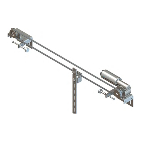
5 Illustrations 5.1 Overview Fig. 1: TSG assembly example Table 1: Designation of TSG universal kit Article number Designation 8.20.40000.X1 TSG drive (shown here: left version) 1.20.60040 TSG standard combination bracket 1.20.60030 TSG stop kit (incl. buffer stop) 1.20.60003 TSG counter roller 1.20.60110 TSG clamping latch 1.20.60013... -
Page 13: Assembly
5.2 Assembly Fig. 2: Assembly TSG counter roller unit Fig. 3: Assembly TSG door panel carrier unit Fig. 4: Assembly TSG motor unit... -
Page 14: Mounting Of The Counter Roller
5.3 Mounting of the counter roller When mounting the counter roller make sure, it is fastened to the side of the pressed-board disk in direction of the holder. Fig. 5: TSG counter roller - mounted... -
Page 15: Dimensions
5.4 Dimensions Fig. 6: TSG universal kit - front dimensions Fig. 7: TSG universal kit - side dimensions... -
Page 16: Tsg Drive: Position Of Motor
5.5 TSG drive: position of motor There are two different motor positions available: The motor position is independent of the direction of opening of the door or the protective device. For example, the TSG drive can be installed on the left or on the right side. Fig. -
Page 17: Tsg Housing
5.6 TSG housing The TSG electronic is available in two different housing types. 5.6.1 TSG electronic intern The TSG electronic is available in a cabinet housing. The cabinet version can be directly screwed in the cabinet onto the mounting plate and / or be mounted on a DIN rail (TS35, 35[mm] x 7,5[mm]). Fig. - Page 18 The motor and encoder cable and single wire for the inputs and outputs are introduced from the bottom. The power supply is above and pluggable. Fig. 12: Guide of the TSG cable in TSG housing Condition for the use of the cabinet housing is to use a plug-in TSG drive and TSG cable. TSG cables are available in lengths of 2.5, 5.0, 10.0, 15.0 and 20.0[m].
- Page 19 5.6.1.1 Dimensional / mounting drawing Fig. 13: TSG intern, front view Fig. 14: TSG intern, rear view Fig. 15: TSG intern, top view...
- Page 20 5.6.2 TSG electronic extern The TSG electronic is available in a splash-proof housing. The housing is mounted by four screws to an ap- propriate position near the TSG drive fixed. Fig. 16: TSG electronic in splash-proof housing The cables can be optionally inserted through the left or right side with cable glands through pro-punched holes in the housing.
- Page 21 5.6.2.1 Dimensional / mounting drawing Fig. 17: TSG extern, side view 1 Fig. 18: TSG extern, top view Fig. 19: TSG extern, side view 2...
-
Page 22: Mechanical Installation
6 Mechanical installation 6.1 Requirements for installation The door must have permanently mounted mechanical end stops for the Open and Closed positions that can withstand the energy applied by the TSG door operator. The end stops must be located on the car in the immediate vicinity of the TSG toothed belt so that the door width is equally wide at all stopping points. -
Page 23: Tsg Toothed Belts
6.3 TSG toothed belts TSG toothed belts must be tensioned to a defined toothed belt tension. This will ensure optimum force transfer and extend the service life of the TSG toothed belt and bearing. Fig. 20: TSG toothed belt tension At an axle distance of: a = 1[m] (axle center –... -
Page 24: Electrical Settings And Commissioning
7 Electrical settings and commissioning 7.1 Display The TSG electronic unit has a two-digit 7-segment display to indicate the current state and show the menu with parameters and their corresponding values. Table 7: TSG display Display Meaning There is no activation. The TSG is not calibrated. -
Page 25: Two-Digit 7-Segment Display
NOTE: If the display is not used for 30 minutes or more, the display switches off automatically. By turning or pressing the jog wheel, the display is switched on again. 7.2 Two-digit 7-segment display The two-digit 7-segment display can show up to 3-digit values. The front part of the number is output at inter- vals of seconds, offset in time from the rear part of the number. -
Page 26: Menu Structure
7.3 Menu structure There is a jog wheel on the TSG electronic for operating and adjusting the TSG door operator (between the 7- segment display and the relay outputs). Press the jog wheel once from Normal mode to show menu item P0. Turn the jog wheel clockwise to move UP (increment) through parameters (increments P1, P2, etc.). -
Page 27: Self-Learn Procedure
7.4 Self-Learn Procedure An initial self-learn procedure must be performed to measure door size. CAUTION: Make certain the door can close and open without obstruction. Otherwise inaccurate data will be recorded. The door must not be obstructed bay objects or sluggish (free movement of door panels and rollers)! During the self-learn procedure there are some uncontrolled door move- ment. -
Page 28: Enter The Weight To Be Traversed
CAUTION: If any mechanical adjustment is performed after the self-learn procedure (example tightening the TSG toothed belt or readjusting the end stops or buffer stops) this will affect the saved values of the door measurements. A new self-learn procedure must be carried out every time a mechanical adjustment has been made! CAUTION: If the function stop input two channel is switched on (h3=04), the connector X1 must be com-... - Page 29 NOTE: A new changing of the weight can only be made by following new self-learn procedure. NOTE: In telescoping doors that is slower by half, the weight of the second door panel must be added only by half. CAUTION: The adjusted weight will not be reset when the parameter EE set the other parameters back to standard (see also Table 17: E parameter / page 58).
-
Page 30: Manual Mode / Manual Travel
7.6 Manual mode / manual travel To select Manual mode, choose parameter P1. The display appears. Turn the jog wheel anticlockwise (c.c.w.) until the display appears. Pressing the jog wheel and holding it down moves the door in the open direction. -
Page 31: Default Parameters
8 Default parameters 8.1 Drive curves with default parameters Geschwindigkeit/ speed öffnen / open Au f/ close open Weg/ Distance Fig. 23: „Open“ door curve with P parameters Geschwindigkeit/ speed schließen / close Auf/ open close Weg/ Distance Fig. 24: „Close“ door curve with P parameters... -
Page 32: Basis Settings
8.2 Basis settings The TSG default parameters are pre-configured. Normally the default parameter’s settings do not need to be changed. WARNING: The adjusted parameters, the maximum speed limit, force and energy are to be checked and recorded at the closing and shearing edges after commissioning or changing of parameters at the door by the executive personnel (see also cap. - Page 33 After the value is set, press the jog wheel to save the displayed value and exit parameters. If you select and press the jog wheel, the menu will skip one step back. NOTE: All parameters that have been changed are permanently saved in the memory, where they will be available even after a power failure.
-
Page 34: Advanced Parameters
9 Advanced parameters 9.1 Drive curves with advanced parameters Fig. 25: „Open“ door curve with c parameters Fig. 26: „Close“ door curve with c parameters... -
Page 35: Advanced Menu
9.2 Advanced menu To go to the advanced menu mode, select parameter P0 and hold down the jog wheel for about 5 [seconds]. Then you can turn the jog wheel to select parameters c, b, h, E, r and Au (see also Fig. 20: Menu structure / page 26). - Page 36 Function Note Default Max Factor Unit Holding torque in Close direction with input signal "Close door" CC Exit the menu. Select CC and press the jog wheel to leave the c-parameter menu and return to c.o. 9.2.2 User setting – b parameters Table 11: b parameters Function Note...
- Page 37 Function Note Max Factor Unit fault Response of relay output "Door oF = Continuous Obstructed" in Open direction on = Pulse Response of the door drive for oF = if door is obstructed the drive blocking in Open direction will stop immediately. If the input signal changes to "Close door", the door closes.
- Page 38 9.2.3 User setting – h parameters Table 12: h-parameters Function Note Max Factor Unit fault Long-term test: Open door / close The door opens and closes re- door / peatedly. Input signals are ig- Adjusting baud rate CAN nored. Between the drives is a pause of 5[seconds].
- Page 39 Function Note Max Factor Unit fault Function input X1.3 00: no function 01: Light Curtain "normally open" If LED 12 is lit open the door 02: Light Curtain "normally closed" If LED 12 is not lit open the door 03: Nudging (see also cap. 12.2 Nudging / page 53) 04: Stop unction two channel (see also cap.
- Page 40 Function Note Max Factor Unit fault Force for verifying the end posi- tion in OPEN Selection mode of operation Only for use with optional add on boards. 00: Opportunity to move to the in- termediate position and Ready for Operation (usable with add on board 4E/4A relays or 4E/4A electronic) 01: control TSG Sinus Drive (usa-...
- Page 41 Function Note Max Factor Unit fault 12: Profinet communication ak- tive (can be used with additional board Profinet). 13: Otis-Multidrop aktive (can be used with additional board Otis- Multidrop). 14: Profinet communication and ZS-operation aktive (can be used with additional board Profinet + 4E/4A electronic).
- Page 42 Function Note Max Factor Unit fault Suppression of Blockage detec- The maximum setting of 50mm is [mm] tion in the last 0mm to 50mm a combination of parameters bb + (maximum) in the close direction. for example: if bb = 10mm then hF ->...
- Page 43 9.2.4 Errors – E parameters Table 13: E parameters Parameter Function Min Standard Max Unit Ready for Reset operation Travel not limited [Number] Automatically after 15[seconds] or power-on reset. Travel path locked [Number] Automatically after 15[seconds] or power-on reset. EEPROM errors [Number] power-on reset Obstructed for...
- Page 44 Parameter Function Min Standard Max Unit Ready for Reset operation Motor not ok [Number] Automatically after 15[seconds]. After a few attempts without changing the drive, stop the Power-On-Reset. Motor detection faulty [Number] Restart directly possible if motor is detected. Load Default Settings oF = Off and clear Error Count on = On...
- Page 45 9.2.5 Operating state – r parameters Table 14: r parameters Parameter Function Unit Comments Actual speed [m/s] Shows the current speed. Target speed [m/s] Shows the given speed. Current motor cur- Shows the current motor current rent Operating voltage of [VDC] Shows the current voltage on the end stage.
- Page 46 9.2.6 User setting – Au parameters Table 15: Au parameters Parameter Function Note Max Factor Unit fault Intermediate position Only with additional board that can be optionally fit- ted, 4E/4A relay or 4E/4A elec- tronic Is the value > 00, the inter- mediate position is active.
- Page 47 Parameter Function Note Max Factor Unit fault Enable parameter A8 See cap. 12.5 Mechanical (mechanical, additional transmission adjustment / ratio) page 58) User-defined parame- ter sets Reset IP address in TVis web interface to 172.16.1.150 (read only) (read only) (read only) (read only) Exit the Au-parameter Select CC and press the jog wheel to leave the r-parameter menu and return to...
-
Page 48: Tsg Signal Connectors
10 TSG signal connectors The terminal markings for power supply, inputs and outputs are independent of the package type. 10.1 Inputs X1 The inputs for signals "Open door" (X1.1), "Close door" (X1.2) and (reserved) (X1.3) can be wired with a voltage of 24 [VDC/AC] (see also Table 21: X1 inputs / page 70). - Page 49 10.1.2.1 Impulse operation variant 1 Variant 1 supports pulse operation at inputs X1.1 and X1.2. Fig. 27: chronological sequence impulse operation (with parameter h1 = 02) If the closing force limitation is triggered during the closing process, the door stops. If it is to close further, the subsequent closing process must be triggered again by a pulse at input X1.2.
-
Page 50: Outputs X2
If input X1.3 triggers a reversing during the closing process, the following closing process is triggered again after the time in parameter h5 has elapsed. If the time in parameter h5 has elapsed and input X1.3 continues to trip, the door remains in the open position until input X1.3 releases the door again. 10.2 Outputs X2 There are three relay outputs on the TSG electronic unit to display or report door status, each with a change- over contact that has contacts terminated on the X2 terminal strip (see also Table 23: X2 relay outputs / page... -
Page 51: Setting For Force Limiting
11 Setting for force limiting The maximum speed limit, force and energy are to be checked and recorded at the closing and shearing edges after commissioning or changing of parameters at the door by the executive personnel. 11.1 Maximum kinetic energy According to the relevant standards, the maximum kinetic energy W to the closing and shear edges 10[J] must not be exceeded. -
Page 52: Obstruction Detection In Closed Direction
11.3 Obstruction detection in Closed direction If the door is obstructed in the Closed direction and obstruction detection is activated (see also Table 11: b parameter / page 36), the door remains stopped as long as the "Close door" signal is present. At the same time the relay switches for "Door Obstructed". -
Page 53: Special Features
12 Special features 12.1 Holding torque in the end positions A holding torque can be set in the end positions. The holding torque causes the door to be held in the corre- sponding end position by an adjustable force. A determination is made whether or not a signal is present at the inputs ("Open door"... -
Page 54: Nudging
12.2 Nudging The nudging function is used in order to push an obstacle that blocks the path in the closing direction at reduced speed out of the way. The nudging is executed when both inputs X1.2 and X1.3 are on. As a prerequisite, the parameter must be set h3 = 03. - Page 55 12.3.1 Stop input single channel The stop input single channel corresponding with the standard EN ISO 13849-1: 2015 PL“b“. Fig. 29: example circuit Stop Kat 0, PL"b" If the connection to the terminal strip X5 between 1 and 2 is open, the motor coasts to stop. It appears in the display .
- Page 56 12.3.2 Stop input two channel The stop input two channels corresponding with the standard EN ISO 13849-1: 2015 PL“d“. Fig. 30: example circuit Stop Kat 0, PL"d"...
-
Page 57: Leading Limit Switch
If the connections to the terminal strip X5 between 1 and 2 and the connection to terminal strip X1.3 are open, the motor coasts to stop. It appears in the display . After reconnecting the TSG door operator restarts in normal mode. -
Page 58: Mechanical Transmission Adjustment
12.5 Mechanical transmission adjustment A permanently set gear ratio is stored in the TSG door control unit as standard. A changed mechanical trans- mission has the consequence that the forces, the speeds and the accelerations are different from the ex- pected ones. - Page 59 Fault/Error Function Meaning Cause Remedy This error is reset after The toothed belt ten- Start the self-learn 15 seconds. During sion has been procedure (see also this time, the door changed. 7.4 Self-Learn Proce- drive does not respond dure / page 27) to input drive signals.
- Page 60 Fault/Error Function Meaning Cause Remedy End stage faulty. Replace TSG elec- tronic. Wrong voltage Check power supply. Incremental encoder Replace the drive. damaged. Cable to the motor is Connect the cable with not connected. the motor. Monitoring triggered Cable to the motor Replace the motor ca- current sensor damaged.
- Page 61 Fault/Error Function Meaning Cause Remedy Replace motor. Motor not ok The connected motor Incorrect door motor Replace motor. is defective. is connected to the TSG electronic. Motor recognition er- The default settings are loaded Caution: all changes will be reset to default! Caution: before load- ing the default set- tings, a currently exe-...
- Page 62 Fault/Error Function Meaning Cause Remedy Load default settings Reset device parame- ters to their factory set- tings. Delete error counters All error counters will Replace drive. be deleted. Caution: the display EH is only shown as long as the error is present.
- Page 63 Fault/Error Function Meaning Cause Remedy CAN bus communica- The CAN bus con- Check TSG electron- tion is interrupted or nected to the addi- ics and additional disturbed. tional board is inter- board. rupted or disturbed. Caution: the display Eu is only shown as long as the error is present.
-
Page 64: Service And Maintenance
Table 18: other causes and troubleshooting Fault Cause Remedy Drive does not run. TSG has no voltage Turn on the mains power voltage. Check LED 1, LED2, LED3 and LED4. Stop input interrupted. There must be a connection between X5.1 and X5.2 (see also cap. -
Page 65: Disposal
15 Disposal Applicable provisions must be observed for disposal: Oil must be disposed of according to the (German) Used Oil Regulation (for example it must not be mixed with solvents, cold cleaners or paint residue) Separate components for recycling by category: Scrap iron Electronic waste Aluminum... -
Page 66: Technical Data For Tsg Electronic
16 Technical data for TSG electronic 16.1 Overview of TSG electronic X1: Inputs LED 1: Operating voltage 38[VDC] X2: Outputs LED 2: Operating voltage 5[VDC] LED 3: Operating voltage 12[VDC] X3: Motor Encoder LED 4: Operating voltage 24[VDC] X4: Motor LED 5: Check LED LED 6: Overload X5: Stop input... -
Page 67: Technical Data
16.2 Technical data Table 19: Technical data Technical data for TSG electronic Connection voltage Input ratings 115V version: Voltage: 115[VAC] ± 15% (L, N, GRD) Current: 1.8[A] No. of phase: 1AC Frequency: 50/60[Hz] Short circuit current: 4.0[A] (internally fused) 200V version: Voltage: 200[VAC] ±... - Page 68 Technical data for TSG electronic Maximum power consumption 115V version: 1.8[A] 200V version: 1.1[A] 230V version: 0.9[A] 400V version: 0.5[A] 480V version: 0.4[A] Note: Higher currents can flow briefly (< 1[sec.]) depending on the door weight and parameter settings. Allowable storage / transport temperature 0 [°C]...60[°C];...
-
Page 69: Restart After Power Off And Restoration Of Mains Power
16.3 Restart after power off and restoration of mains power After power off, when power is restored, the TSG door operator searches for the programmed end positions. For this the TSG door operator drives with slow speed until both end positions are reached and identified. The value for the speed is set in parameter h6. -
Page 70: Plug / Terminal Assignment Of Tsg Electronic
16.5 Plug / terminal assignment of TSG electronic 16.5.1 Terminal assignment signal inputs Table 21: X1 inputs X1 inputs (8-pin push-in spring connection): X1.1 "Open door" input 16 – 28 [Vdc] / min. 10mA X1.2 "Close door" input 16 – 28 [Vdc] / min. 10mA X1.3 (Reserved) input 16 –... - Page 71 16.5.2 Terminal assignment relay outputs Table 23: X2 relay outputs X2 relay outputs (9-pin push-in spring connection): X2.1 "Door is Open" output – common X2.2 "Door is Open" output - n.c. (normally closed contact) X2.3 "Door is Open" output - n.o. (normally open contact) X2.4 "Door is Closed"...
- Page 72 CAUTION: No voltages of different mains power supplies may be connected to the relay outputs (for ex- ample 24 V and 80 V at the same time)! 16.5.3 Terminal assignment encoder Table 26: X3 Incremental encoder assignment – fixed cable on motor X3 incremental encoder (9-pin SubD): (free) (free)
- Page 73 16.5.4 Terminal assignment motor Table 28: X4 motor connection X4 motor connection (2-pin screw connector): Motor + Brown Motor - White Motor shield via cable lug 4.8x0.8 Housing CAUTION: Before connecting or disconnecting the motor connection plug, the power supply must be turned off first! CAUTION: The assignment of the motor connection from Table 28 / page 73 must not be changed.
- Page 74 16.5.5 Terminal assignment power The TSG door control unit is available with different mains supply voltages. The mains voltage that can be connected to the device is indicated on the respective nameplate of the device. TSG electronics external version: Fig. 31: TSG Electronic external - Mains voltage connection TSG electronics internal version: Fig.
- Page 75 Table 29: Mains power connection 115VAC Main power connection 115V-Version: 115[VAC] ± 15% / 50/60[Hz] X20GRD protective conductor terminal Table 30: Mains power connection 200VAC Main power connection 230V-Version: 200[VAC] ± 15% / 50/60[Hz] X20GRD protective conductor terminal Table 31: Mains power connection 230VAC Mains power connection 230V version: 230[VAC] ±...
-
Page 76: Connection Of External Control Voltage
16.6 Connection of external control voltage It is possible to replace the internal transformer supplied standard control voltage through customer connec- tion. The control voltage supplies the logical part of the TSG electronic and the encoder of the TSG motor. The main part of the TSG electronic continues to be supplied from the power supply. -
Page 77: Stop-Function Connection
16.7 Stop-function connection The TSG electronics has a stop function, which can be designed as single-channel or dual-channel. During normal operation and without using the stop function, there is a wire bridge between X5.1 and X5.2. Table 37: Stop-function X5 Connection of the stop function X5: X5.1 Potential-free contact... -
Page 78: Connection Circuit Diagram For Tsg Inputs
17 Connection circuit diagram for TSG inputs Fig. 33: Connection option with internal 24[VDC] power supply voltage Fig. 34: Connection option with external Fig. 35: Connection option with external 24[VDC] power supply voltage and common 24[VDC] power supply voltage and common positive negative... -
Page 79: Tsg Options
18 TSG options 18.1 TSG webinterface The TSG web interface is an additional electronic module (optionally available) that can be used together with the TVis-Web software to connect the TSG door control device with a PC or notebook. TVis-Web is a program for visualising the TSG door control device on a PC or notebook. You don’t have to install software on your PC. -
Page 80: Emergency Power Supply
18.3 Emergency power supply The TSG electronic is optionally available with an emergency power supply. The emergency power supply consists of an additional electronic part on the TSG board and two batteries (NiMh). In case of main power failure, the door can be opened or closed. The number of trips and the speed depends on the weight and the smoothness of the door to be traversed. -
Page 81: Light Curtain Kit
18.4 Light Curtain Kit The TSG can be equipped with an additional light curtain. The light curtain consists of a transmitter and re- ceiver bar which monitor the door opening for obstructions. To simplify the assembly, the TSG Light Kit is fitted with pre-wired plug-in cables. - Page 84 Langer & Laumann Ing.-Büro GmbH Wilmsberger Weg 8 48565 Steinfurt Germany Tel.: +49 (2552) 92791 0 Email: info@lul-ing.de www.lul-ing.de...