
Related Manuals for Samsung 136S


Summary of Contents for Samsung 136S
- Page 1 Confidential LIB System for UPS Installation Manual (136S) English 8/2019. Rev 0.0...
- Page 2 Confidential Read this manual carefully before starting to install the battery system. Keep these instructions for future reference. English 8/2019. Rev 0.0...
- Page 3 Copyright © 2019 SAMSUNG SDI Co., Ltd. All rights reserved. This document contains information that is the property of SAMSUNG SDI Co., Ltd., and provides for the sole purpose of the installation, operation, and maintenance of products of SAMSUNG SDI Co., Ltd. No part of...
- Page 4 Confidential English 8/2019. Rev 0.0...
-
Page 5: Important Safety Instructions
Confidential Important Safety Instructions Important Safety Instructions Read and follow these instructions! The following precautions are intended to ensure your safety and prevent property damage. Before installing this product, be sure to read all safety instructions in this document for proper installation. DANGER Failure to comply with the instructions with this symbol may result in a serious accident, causing death or a severe injury. -
Page 6: General Instructions
Confidential Important Safety Instructions General Instructions Please be aware that a battery presents a risk of electrical shock including high short-circuit current. Follow all safety precautions while operating the batteries. Remove watches, rings, and other metallic accessories. Use tools with insulated handles in order to avoid inadvertent short circuits. ... -
Page 7: Personnel And Equipment Warnings
Confidential Important Safety Instructions Personnel and Equipment Warnings Personnel in contact with the battery system should be aware of the following hazards: WARNING—SHOCK HAZARD Do not contact system connectors or terminals. Do not open the enclosure doors unless proper lock out/tag out procedures and related trainings are followed in accordance with the local codes and regulations. -
Page 8: Lock Out/Tag Out Guidelines
ESS. The lock out/tag out procedures must meet or exceed the requirements of all guidelines presented in SAMSUNG SDI safety documentation. Before entering potentially hazardous areas or beginning work on the ESS, complete the following tasks: ... - Page 9 Confidential Important Safety Instructions WARNING To avoid personal injury or equipment damage caused by equipment malfunction, only adequately trained personnel should modify any programmable machine. WARNING Always ensure that applicable standards and regulations are followed and only properly certified equipment is used as a critical component of a safety system. Never assume that a safety-critical control loop is functioning correctly.
- Page 10 Confidential Important Safety Instructions English 8/2019. Rev 0.0...
-
Page 11: Table Of Contents
Table of Contents Confidential Table of Contents Important Safety Instructions ......................... i General Instructions ............................ii Safety Precautions ............................ii Personnel and Equipment Warnings .......................iii Dangerous Voltages ............................iii Lock Out/Tag Out Guidelines ..........................iv General Warnings ............................iv Table of Contents ........................... i Tables .............................. - Page 12 Confidential Table of Contents 3.10.3 Battery Module Installation ....................45 3.10.4 Fuse-Busbar Assembly ......................48 3.10.5 Busbar Installation ........................ 51 3.10.6 Module and SMU Signal Cable Connection ................85 3.10.7 SMPS Assembly and SMU Power Cable Connection ............... 97 3.10.8 SMPS Assembly and SMU Signal Cable Connection ..............98 3.10.9 SMPS Assembly AC Input Connection ..................
-
Page 13: Tables
Table 2-9: Dry Contact Operation (Customer ID = 1)....................15 Table 2-10: Dry Contact Operation (Customer ID = 2) ....................15 Table 3-1: Estimated time for installation (based on 136S 3P installation) ..............21 Table 3-2: Parts for 136S 3P Rack ..........................23 Table 3-3: Ground Wire Specifications ........................ -
Page 14: Figures
Confidential Table of Contents Figures Figure 2-1: Battery Module Type A ............................5 Figure 2-2: Battery Module Type B ............................6 Figure 2-3: SMU ..................................7 Figure 2-4: Auxiliary Breaker Switch ............................8 Figure 2-5: Terminal Block Isometric View ..........................8 Figure 2-6: Terminal Block Front / Top View (Cover Opened/Closed) ................. - Page 15 Table of Contents Confidential Figure 3-38: Restore SMU’s B- Terminal ..........................53 Figure 3-39: Remove Battery Module #2’s Front Cover ...................... 53 Figure 3-40: Connect Battery Module #1 B+ and Battery Module #2 B-................54 Figure 3-41: Reattach Battery Module #1’s Front Cover ..................... 54 Figure 3-42: Remove Battery Module #2’s Front Cover ......................
- Page 16 Confidential Table of Contents Figure 3-91: Module #1 to Module #2 Signal Cabling ......................86 Figure 3-92: Module #2 to Module #3 Signal Cabling ......................86 Figure 3-93: Module #3 to Module #4 Signal Cabling ......................87 Figure 3-94: Module #4 to Module #5 Signal Cabling ......................87 Figure 3-95: Module #5 to Module #6 Signal Cabling ......................
- Page 17 Table of Contents Confidential Figure 3-144: BATTMON Icon ............................. 119 Figure 3-145: BATTMON Splash Window .......................... 120 Figure 3-146: Rack BMS - CONFIG connection window ....................120 Figure 3-147: Rack BMS Config Setting window ....................... 121 Figure 3-148: Cable Connections for System BMS Configuration ..................122 Figure 3-149: BATTMON Icon .............................
- Page 18 Confidential Table of Contents viii English 8/2019. Rev 0.0...
-
Page 19: About This Manual
Confidential About this Manual 1. About this Manual To make sure that you understand the proper procedures for safe operation, this section briefly describes the purpose, audience, organization, revision history, and acronyms and abbreviations. 1.1 Purpose The purpose of this manual is to provide information for the safe and successful installation of the product The instructions in this manual are based on assembly of a three-cabinet system. -
Page 20: Revision History
Confidential About this Manual 1.4 Revision History Rev. Description Author Date First Draft 2019.08.20 Approved By: Name Signature Date Reviewers Name Signature Date English 8/2019. Rev 0.0... -
Page 21: Acronyms And Abbreviations
Confidential About this Manual 1.5 Acronyms and Abbreviations The following acronyms and abbreviations are used in this manual. Abbreviations Full Name Automated External Defibrillator Battery Management System Environmental Health and Safety Energy Storage System LOTO LOCK OUT/TAG OUT Overtemperature Overvoltage Protection Power Conversion System String Management Unit SMPS... -
Page 22: Product Description
Confidential Product Description 2. Product Description Check the components for installation. For more information, please refer to the product specification. 2.1 Major Components This product has the following components: Battery Module (Type A / Type B) SMU Rack BMS (Embedded in SMU) ... -
Page 23: Battery Module (Type A / Type B)
Confidential Product Description 2.1.1 Battery Module (Type A / Type B) Battery Module is the most basic component of the Battery System and it contains the energy storing battery cells. There is a Module BMS inside each Battery Module. Module BMS checks the status of a Battery Module by measuring its voltage and temperature. -
Page 24: Figure 2-2: Battery Module Type B
Confidential Product Description Battery Module Type B (Isometric) Battery Module Type B (Front. Front cover removed) Figure 2-2: Battery Module Type B English 8/2019. Rev 0.0... -
Page 25: Smu (String Management Unit)
Confidential Product Description 2.1.2 SMU (String Management Unit) SMU collects all information about the battery system and controls the battery system by switching the main power line and controls each Battery Module by cell balancing. SMU calculates the state-of-charge (SOC) and state- of-health (SOH) of the battery system. -
Page 26: Table 2-1: Extra Auxiliary Breaker Switch Connector Description
Confidential Product Description SMU provides an auxiliary breaker switch that can be connected to the building monitoring system. Figure 2-4: Auxiliary Breaker Switch Table 2-1: Extra Auxiliary Breaker Switch Connector Description Item Part Name Description Connector J21SPM-04V-KX Harness Housing J21SF-04V-KX-L Harness Terminal SJ2F-01GF-P1.0 AWG 20~24... -
Page 27: Table 2-2: Terminal Block Description
Confidential Product Description Top View Front View COVER OPEN COVER CLOSED Figure 2-6: Terminal Block Front / Top View (Cover Opened/Closed) Table 2-2: Terminal Block Description Item Detail Description Conducting Material C1100 Insulating Material (Guide) PA66 GF25% Insulating Material (Cover) Conductive Area 32.5mm x 40.0mm Rated Current... -
Page 28: Smps Assembly (Type A / Type B)
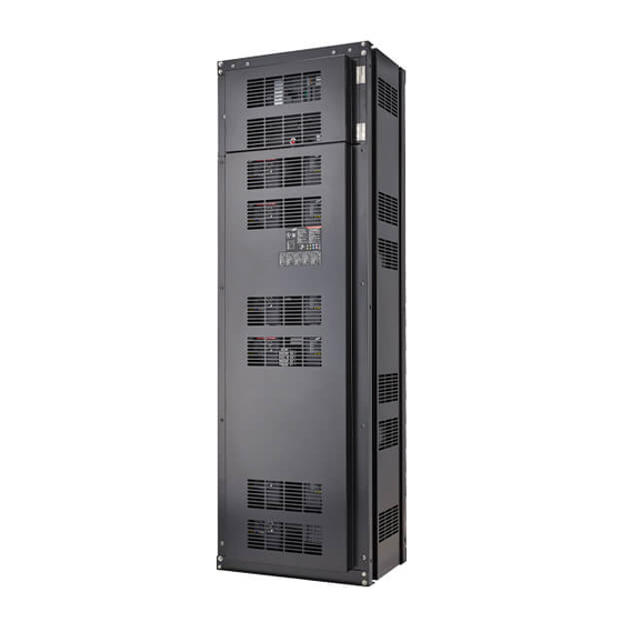
Confidential Product Description 2.1.3 SMPS Assembly (Type A / Type B) stem BMS): V044-0006XA 3-Phase Type A (with Sy X = A (for general customer) X = B (for specific customer) 3-Phase Type B (without System BMS): SJ94-00238B (for general customer) 1-Phase Type A (with System BMS): V044-0004XA X = A (for general customer) X = B (for specific customer) -
Page 29: Figure 2-8: Smps Assembly Type B
Confidential Product Description SMPS Assembly with 3 Phase AC Input SMPS Assembly with 1 Phase AC Input Type B (without System BMS) Figure 2-8: SMPS Assembly Type B Figure 2-9: Front View of SMPS Assembly Type A, 3-Phase Input Figure 2-10: Front View of SMPS Assembly Type A, 1-Phase Input Figure 2-11: SMPS Assembly Type A –... -
Page 30: Figure 2-12: Front View Of Smps Assembly Type B, 1-Phase Input
Confidential Product Description Figure 2-12: Front View of SMPS Assembly Type B, 1-Phase Input English 8/2019. Rev 0.0... -
Page 31: Table 2-3: Rs485 Connector Description
Confidential Product Description SMPS Assembly Type A provides RS485, TCP/IP and Dry contact. Table 2-3: RS485 Connector Description Item Part Name Description Connector IM25G-008-256 2 Port, RJ45 Harness Housing RJ45 Harness Terminal RJ45 Pin No. Pin Name Function Left. 1 Left. -
Page 32: Table 2-5: Dry Contact Connector Description
Confidential Product Description Table 2-5: Dry Contact Connector Description Item Part Name Description Connector S12B-J11DK-TXR Harness Housing J11DF-12V-KX Harness Terminal SF1F-21T-P0.6 AWG 18~22 Pin No. Pin Name Function DRY CONTACT 0 NC DRY CONTACT 1 COM DRY CONTACT 1 NO DRY CONTACT 2 NC DRY CONTACT IN- (GND) Refer to the product specification. -
Page 33: Table 2-8: Dry Contact Operation (Customer Id = 0)
Confidential Product Description Table 2-8: Dry Contact Operation (Customer ID = 0) Pin No. Pin Name Function Major Common Over-Voltage Protection Under-Voltage Protection Major Normal Close Over-Temperature Protection Major Normal Open Over-Current Protection Minor Common Voltage Imbalance Error Voltage Sensing Error Minor Normal Close Under Temperature protection Minor Normal Open... - Page 34 Confidential Product Description Table 11: SMPS Status (SMPS Assembly 1 Phase Only) Item Part Name Description Connector J21SPM-04V-KX Harness Housing J21SF-04V-KX-L Harness Terminal SJ2F-01GF-P1.0 AWG 20~24 Pin No. Pin Name Function SMPS #1 STATUS (+) SMPS #1 status SMPS #1 STATUS (-) SMPS #1 status SMPS #2 status SMPS #2 STATUS (+)
-
Page 35: Rack Frame
Confidential Product Description 2.1.4 Rack Frame White: V808-00066A Black: V808-00068A The Rack Frame is used to mount the modules, SMU and SMPS assembly and provides ground connections for SMU and SMPS Assembly. (Grounding cable/busbar for the rack frame is necessary for the SMU and SMPS Assembly as they are grounded to the rack frame when installed. -
Page 36: Installing The Product
Grounding is required to prevent electric shock hazards and reduce or eliminate damage caused by electrical noise. Ground connections and ground wire routing vary significantly depending on system configuration and equipment layout. Samsung provides grounding strip on top of each rack. See Figure 3-128: Grounding Points (2 EA). English 8/2019. Rev 0.0... -
Page 37: Arc Flash Calculations
Arc flash related calculation of the battery system is estimated with the Direct-Current Incident Energy Calculations referenced in Informative Annex D of NFPA 70E Standard for Electrical Safety in the Workplace. The following battery system is assumed to estimate the worst-case scenario Battery configuration: 136S Battery voltage: 571.2V Battery internal resistance (AC IR): 65mohm... -
Page 38: Installation Procedure
Confidential Installing the Product 3.3 Installation Procedure This product must be installed by following the procedure below: 3. Rack 1. Preparation 2. Rack Anchoring 4. System Installation Stage Stage Installation Stage Stage Figure 3-1: Installation Procedure Preparation Stage Procedure ... -
Page 39: Table 3-1: Estimated Time For Installation (Based On 136S 3P Installation)
Confidential Installing the Product Table 3-1: Estimated time for installation (based on 136S 3P installation) Estimated Time Aggregated Time Step (HH:MM) (HH:MM) Unpacking 00:30 00:30 Inspection 01:00 01:30 Rack Anchoring 04:00 05:30 Battery Module 00:20 05:50 00:10 06:00 SMPS Assembly... -
Page 40: Preparation Stage-Procedure
Confidential Installing the Product 3.4 Preparation Stage—Procedure For the preparation stage, perform the following steps: 1. Create the installation plan and check the equipment and instruments for installation. 2. Check the arrival schedule of the parts required. 3. Unpack the equipment. 4. -
Page 41: Preparation Stage-Unpacking
Confidential Installing the Product 3.5 Preparation Stage—Unpacking Check the following parts during unpacking: Table 3-2: Parts for 136S 3P Rack Amount Items Part No. Remarks (Unit: EA) V808-00066A V808-00066A: White, for specific customer RACK FRAME V808-00068A V808-00068A: Black, for general customer... -
Page 42: Preparation Stage-Ground Wire And Tools
SS304 (Bottom Anchor) 3.6.4 Multiple Rack Fasteners Rack fasteners are factory-provided. Refer to Table 3-2: Parts for 136S 3P Rack for part number and quantities. Specifications for the rack fastener screws for installing multiple rack frames side-by-side are: Table 3-6: Rack Fastener Specifications (Side by side) -
Page 43: Preparation Stage-Recommended Tools/Instruments
Confidential Installing the Product 3.7 Preparation Stage—Recommended Tools/Instruments Installers must provide these tools for installing the battery: Table 3-7: Recommended Tools and Instruments Items Usage Appearance To fasten SMU and SMPS assemblies to Power Screwdriver/Drill the rack frames (Max torque: 26Nm/270 kgf/cm) (5.1–6.1Nm/50–60 kgf/cm) Torque Limiter For use with torque wrench... - Page 44 Confidential Installing the Product Items Usage Appearance Measure battery module’s voltage and Battery Tester internal impedance English 8/2019. Rev 0.0...
-
Page 45: Preparation Stage-Visual Inspection
Installing the Product 3.8 Preparation Stage—Visual Inspection CAUTION If any defects are found during the inspection, contact the SAMSUNG SDI customer service department. 3.8.1 Inspection of the Rack Frame After transporting the rack frame to the installation location, check for: ... -
Page 46: Inspecting The Smps Assembly
Confidential Installing the Product 3.8.4 Inspecting the SMPS assembly After transporting the SMPS Assembly to its installation location, check for: Physical damage Paint peeling Damaged or protruding screws. After completion, install the SMPS in the previously installed rack or return the SMPS to its original packing for protection during storage. -
Page 47: Rack Anchoring Stage
Confidential Installing the Product 3.9 Rack Anchoring Stage Install the rack frame on a flat, level surface. To attach the rack and perform the related works CAUTION Use a proper transportation method considering the weight of the rack frame. ... -
Page 48: Figure 3-2: Clearance Distance For Single Rack Frame
Confidential Installing the Product Configuration Anchor points per rack Clearance Distance (mm) Side (end) Side (adjacent) Rear Front (Side-to-Side not rated for seismic event (1000 recommended) and Rear-to- 4 (All) – Telcordia Zone 4 Workable distance Workable distance Workable distance Rear) (800 recommended) (800 recommended) -
Page 49: Figure 3-4: Clearance Distance For Multiple Rack Frames Installed Side-By-Side And Rear-To-Rear
Confidential Installing the Product Two anchor points (not rated for seismic event) Four anchor points (Telcordia Zone 4) Figure 3-4: Clearance Distance for Multiple Rack Frames Installed Side-by-Side and Rear-to-Rear 1. After unpacking the rack frame, transport it to its installation location. 2. -
Page 50: Figure 3-6: Front Panel Hooks (Four)
Confidential Installing the Product Figure 3-6: Front panel hooks (four) Figure 3-7: Side panel screws (six) English 8/2019. Rev 0.0... -
Page 51: Figure 3-8: Side Panel Hooks (Four)
Confidential Installing the Product Figure 3-8: Side panel hooks (four) Figure 3-9: Rear panel screws (eight) English 8/2019. Rev 0.0... -
Page 52: Figure 3-10: Rear Panel Hooks (Four)
Confidential Installing the Product Figure 3-10: Rear panel hooks (four) 3. Arrange the rack frame after verifying that the holes in the frame and anchoring points are aligned. 4. Connect four anchoring points on the bottom of the rack. NOTICE ... -
Page 53: Figure 3-12: Holes On The Sides Of The Rack (Six)
Confidential Installing the Product 5. Connect the racks together using M10 hardware through holes in the sides (“SCREW M10 X 25,” “M10 FLAT WASHER” and “NUT M10”). Torque the bolts to 30Nm (300kgf cm). Figure 3-12: Holes on the sides of the rack (six) 6. -
Page 54: Figure 3-13: Reattaching The Side Panels (Four Hooks And Six Screws For Each Panel)
Confidential Installing the Product Figure 3-13: Reattaching the Side Panels (four hooks and six screws for each panel) 7. Reattach the rear panels to the rack frames using the provided M5 Screws for each rear panel. Fasten the screws using torque of 5.1–6.1 Nm (50–60 kgf/cm). -
Page 55: Figure 3-14: Reattaching The Rear Panels
Confidential Installing the Product Figure 3-14: Reattaching the Rear Panels 8. Front panels will be reattached after all the components are installed. English 8/2019. Rev 0.0... -
Page 56: Rack Installation Stage
Confidential Installing the Product 3.10 Rack Installation Stage WARNING Arc Flash and Shock Hazard Insulated tools are required for any work on this energized equipment. WARNING Sharp Edges Wear gloves and other protective gear to prevent injury. WARNING Pinch Point Use caution when working in the enclosure to prevent injury. -
Page 57: Front Door Removal
Confidential Installing the Product 3.10.1 Front Door Removal 1. Open the front door of the panel using the provided key. Figure 3-15: Front door ajar 2. Remove the earth cable from the rack frame to the front door. Do not misplace the two screws and the earth cable. Figure 3-16: Removing the earth cable 3. -
Page 58: Figure 3-17: Removing The Front Door
Confidential Installing the Product Figure 3-17: Removing the front door 4. If installing more than one rack, remove all the doors. Figure 3-18: All doors and front panels removed. English 8/2019. Rev 0.0... -
Page 59: Smu And Smps Assembly Installation
Confidential Installing the Product 3.10.2 SMU and SMPS Assembly Installation Important Attach each SMU to its rack frame with four M5 x 10L screws. (Torque: 5.1–6.1 Nm [50–60 kgf cm]) Verify that the torque setting is correct. 1. Insert the SMU through the front of the rack as shown in Figure 3-19: Inserting SMU Figure 3-19: Inserting SMU 2. -
Page 60: Figure 3-21: Ground Cable Connection To The Smu
Confidential Installing the Product NOTICE Connect a ground cable between the SMU and the Rack Frame (SCREW M5 x 10L). (Torque: 5.1–6.1 Nm [50–60 kgf∙cm]) Verify that the torque setting is correct. Figure 3-21: Ground Cable Connection to the SMU English 8/2019. -
Page 61: Figure 3-22: Inserting Smps Assembly
Confidential Installing the Product 4. Insert SMPS Assembly into the rack frames designated for SMPS Assembly as shown in Figure 3-22: Inserting SMPS Assembly Important Attach the inserted SMPS Assemblies to the rack frames by fastening each with four M5 x 10Lscrews ... -
Page 62: Figure 3-24: Ground Cable Connection To The Smps Assembly
Confidential Installing the Product NOTICE Connect a ground cable between the SMPS Assembly and the Rack Frame with an M5 x 10L screw. (Torque: 5.1–6.1 Nm [50–60 kgf cm]) Verify that the torque setting is correct. Figure 3-24: Ground Cable Connection to the SMPS Assembly English 8/2019. -
Page 63: Battery Module Installation
3. Place the battery modules on the rack frame. Important Samsung recommends installing Battery Modules in the upper shelves first and proceeding to the bottom. (Two Type B battery modules are inserted in the ninth shelf from the bottom.) ... -
Page 64: Figure 3-26: Battery Module Arrangement On The Eighth Shelf
Confidential Installing the Product Two Type A Battery Modules Figure 3-26: Battery Module Arrangement on the Eighth Shelf Two Type B Battery Modules Two Type A Battery Modules Two Type B Battery Modules Two Type A Battery Modules Two Type B Battery Modules Two Type A Battery Modules Two Type B Battery Modules... -
Page 65: Figure 3-28 : Module Number
Module #9 Figure 3-28 : Module Number Important Samsung recommends installing modules from top to bottom. The bottom shelf (1 shelf) has one Type B module in the left slot, as shown in Figure 3-29. Figure 3-29: Insertion of modules on 1st shelf... -
Page 66: Fuse-Busbar Assembly
Confidential Installing the Product 3.10.4 Fuse-Busbar Assembly Three types of fuse-busbar assemblies must be assembled before installing them to the Battery Modules. NOTICE Rack Fuse Busbar Assembly is assembled at the installation location. M12 X 16L screws are used to assemble the busbars and fuse. The fastening torque should be 30 Nm (300 kgf/cm). -
Page 67: Figure 3-32: Fuse Busbar Left Assembly
Confidential Installing the Product 2. Assemble the Fuse Busbar Left Assembly. Fuse Busbar Left Assembly is comprised of one “FUSE BUSBAR LEFT UPPER”, one one “FUSE BUSBAR LEFT LOWER”, two “SCREW M12 X 16”, two “FUSE COVER #2”, and one “FUSE” Figure 3-32: Fuse Busbar Left Assembly Figure 3-33: Fuse Busbar Left Assembly (Fuse Cover) English 8/2019. -
Page 68: Figure 3-34: Fuse Busbar Right Assembly
Confidential Installing the Product 3. Assemble the Fuse Busbar Right Assembly. Fuse Busbar Right Assembly is comprised of one “FUSE BUSBAR RIGHT UPPER”, one one “FUSE BUSBAR RIGHT LOWER”, two “SCREW M12 X 16”, two “FUSE COVER #2”, and one “FUSE” Figure 3-34: Fuse Busbar Right Assembly Figure 3-35: Fuse Busbar Right Assembly (Fuse Cover) English 8/2019. -
Page 69: Busbar Installation
Confidential Installing the Product 3.10.5 Busbar Installation Connect the power busbars between modules Verify with a voltmeter that no power is present on the system. Use lock out/tag out procedures to secure the UPS and batteries. CAUTION Please follow the instructions to protect the module BMS against damage. ... -
Page 70: Figure 3-36: Removing The Module #1'S Cover And Smu B- Terminal Cover
Confidential Installing the Product 1. Remove Battery Module #1’s front cover and the SMU B- terminal cover. Figure 3-36: Removing the Module #1’s Cover and SMU B- Terminal Cover 2. Connect SMU B- and Module #1 B- using “BUSBAR M TO SMU.” SMU B- terminal is connected using an M12 screw and Battery Module #1 B- terminal is connected using an M8 screw. -
Page 71: Figure 3-38: Restore Smu's B- Terminal
Confidential Installing the Product 3. Reattach SMU’s B- terminal cover. Figure 3-38: Restore SMU’s B- Terminal 4. Remove Battery Module #2’s front cover. Figure 3-39: Remove Battery Module #2’s Front Cover English 8/2019. Rev 0.0... -
Page 72: Figure 3-40: Connect Battery Module #1 B+ And Battery Module #2 B
Confidential Installing the Product 5. Connect Battery Module #1 B+ and Module #2 B- using “BUS-BAR MAIN.” Connect using an M8 screw. Figure 3-40: Connect Battery Module #1 B+ and Battery Module #2 B-. 6. Reattach Battery Module #1’s front cover and remove Battery Module #3’s front cover. Figure 3-41: Reattach Battery Module #1’s Front Cover English 8/2019. -
Page 73: Figure 3-42: Remove Battery Module #2'S Front Cover
Confidential Installing the Product Figure 3-42: Remove Battery Module #2’s Front Cover 7. Connect Battery Module #2 B+ and Battery Module #3 B- using “BUS-BAR MAIN.” Connect using an M8 screw. Figure 3-43: Connect Battery Module #2 B+ and Battery Module #3 B-. English 8/2019. -
Page 74: Figure 3-44: Reattach Battery Module #2'S Front Cover
Confidential Installing the Product 8. Reattach Battery Module #2’s front cover and remove Battery Module #4’s front cover. Figure 3-44: Reattach Battery Module #2’s Front Cover Figure 3-45: Remove Battery Module #4’s Front Cover English 8/2019. Rev 0.0... -
Page 75: Figure 3-46: Connect Battery Module #3 B+ And Module #4 B
Confidential Installing the Product 9. Connect Battery Module #3 B+ and Module #4 B- using “BUS-BAR MAIN.” Connect using an M8 screw. Figure 3-46: Connect Battery Module #3 B+ and Module #4 B-. English 8/2019. Rev 0.0... -
Page 76: Figure 3-47: Reattach Battery Module #3'S Front Cover
Confidential Installing the Product 10. Reattach Battery Module #3’s front cover and remove Battery Module #5’s front cover. Figure 3-47: Reattach Battery Module #3’s Front Cover Figure 3-48: Remove Battery Module #5’s Front Cover English 8/2019. Rev 0.0... -
Page 77: Figure 3-49: Connect Battery Module #4 B+ And Battery Module #5 B
Confidential Installing the Product 11. Connect Battery Module #4 B+ and Battery Module #5 B- using “BUS-BAR MAIN.” Connect using an M8 screw. Figure 3-49: Connect Battery Module #4 B+ and Battery Module #5 B-. English 8/2019. Rev 0.0... -
Page 78: Figure 3-50: Reattach Battery Module #4'S Front Cover
Confidential Installing the Product 12. Reattach Battery Module #4’s front cover and remove Battery Module #6’s front cover. Figure 3-50: Reattach Battery Module #4’s Front Cover Figure 3-51: Remove Battery Module #6’s Front Cover English 8/2019. Rev 0.0... -
Page 79: Figure 3-52: Connect Battery Module #5 B+ And Battery Module #6 B
Confidential Installing the Product 13. Connect Battery Module #5 B+ and Battery Module #6 B- using “FUSE BUSBAR RIGHT ASSEMBLY”. Connect using an M8 screw. Figure 3-52: Connect Battery Module #5 B+ and Battery Module #6 B-. English 8/2019. Rev 0.0... -
Page 80: Figure 3-53: Reattach Battery Module #5'S Front Cover
Confidential Installing the Product 14. Reattach Battery Module #5’s front cover and remove Battery Module #7’s front cover. Figure 3-53: Reattach Battery Module #5’s Front Cover Figure 3-54: Remove Battery Module #7’s Front Cover English 8/2019. Rev 0.0... -
Page 81: Figure 3-55: Connect Battery Module #6 B+ And Battery Module #7 B
Confidential Installing the Product 15. Connect Battery Module #6 B+ and Battery Module #7 B- using “BUS-BAR MAIN.” Connect using an M8 screw. Figure 3-55: Connect Battery Module #6 B+ and Battery Module #7 B- English 8/2019. Rev 0.0... -
Page 82: Figure 3-56: Reattach Battery Module #6'S Front Cover
Confidential Installing the Product 16. Reattach Battery Module #6’s front cover and remove Battery Module #8’s front cover. Figure 3-56: Reattach Battery Module #6’s Front Cover Figure 3-57: Remove Battery Module #8’s Front Cover English 8/2019. Rev 0.0... -
Page 83: Figure 3-58: Connect Battery Module #7 B+ And Battery Module #8 B
Confidential Installing the Product 17. Connect Battery Module #7 B+ and Battery Module #8 B- using “BUS-BAR MAIN.” Connect using an M8 screw. Figure 3-58: Connect Battery Module #7 B+ and Battery Module #8 B- 18. Reattach Battery Modules #7’s front cover and remove Battery Modules #9’s front cover. Figure 3-59: Reattach Battery Modules #7’s Front Cover English 8/2019. -
Page 84: Figure 3-60: Remove Battery Modules #9'S Front Cover
Confidential Installing the Product Figure 3-60: Remove Battery Modules #9’s Front Cover English 8/2019. Rev 0.0... -
Page 85: Figure 3-61: Connect Battery Module #8 B+ And Battery Module #9 B
Confidential Installing the Product 19. Connect Battery Module #8 B+ and Battery Module #9 B- using “RACK FUSE BUSBAR ASSEMBLY” Connect using an M8 screw. Figure 3-61: Connect Battery Module #8 B+ and Battery Module #9 B-. 20. Reattach Battery Module #8’s front cover and remove Battery Module #10’s front cover. Figure 3-62: Reattach Battery Modules #8’s Front Cover English 8/2019. -
Page 86: Figure 3-63: Remove Battery Modules #10'S Front Cover
Confidential Installing the Product Figure 3-63: Remove Battery Modules #10’s Front Cover 21. Connect Battery Module #9 B+ and Battery Module #10 B- using “BUS-BAR MAIN” Connect using an M8 screw. Figure 3-64 Connect Battery Module #9 B+ and Battery Module #10 B-. 22. -
Page 87: Figure 3-65: Reattach Battery Module #9'S Front Cover
Confidential Installing the Product Figure 3-65: Reattach Battery Module #9’s Front Cover Figure 3-66: Remove Battery Module #11’s Front Cover English 8/2019. Rev 0.0... -
Page 88: Figure 3-67: Connect Battery Module #10 B+ And Battery Module #11 B
Confidential Installing the Product 23. Connect Battery Module #10 B+ and Battery Module #11 B- using “BUS-BAR MAIN.” Connect using an M8 screw. Figure 3-67: Connect Battery Module #10 B+ and Battery Module #11 B-. English 8/2019. Rev 0.0... -
Page 89: Figure 3-68: Reattach Battery Module #10'S Front Cover
Confidential Installing the Product 24. Reattach Battery Module #10’s front cover and remove Module #12’s front cover. Figure 3-68: Reattach Battery Module #10’s Front Cover Figure 3-69: Remove Battery Module #12’s Front Cover English 8/2019. Rev 0.0... -
Page 90: Figure 3-70: Connect Battery Module #11 B+ And Battery Module #12 B
Confidential Installing the Product 25. Connect Battery Module #11 B+ and Battery Module #12 B- using “BUS-BAR MAIN.” Connect using an M8 screw. Figure 3-70: Connect Battery Module #11 B+ and Battery Module #12 B-. English 8/2019. Rev 0.0... -
Page 91: Figure 3-71: Reattach Module #11'S Front Cover
Confidential Installing the Product 26. Reattach Battery Module #11’s front cover and remove Battery Module #13’s front cover. Figure 3-71: Reattach Module #11’s Front Cover Figure 3-72: Remove Module #13’s Front Cover English 8/2019. Rev 0.0... -
Page 92: Figure 3-73: Connect Battery Module #12B+ And Battery Module #13 B
Confidential Installing the Product 27. Connect Battery Module #12 B+ and Battery Module #13 B- using “BUS-BAR MAIN.” Connect using an M8 screw. Figure 3-73: Connect Battery Module #12B+ and Battery Module #13 B-. English 8/2019. Rev 0.0... -
Page 93: Figure 3-74: Reattach Module #12'S Front Cover
Confidential Installing the Product 28. Reattach Battery Module #12’s front cover and remove Battery Module #14’s front cover. Figure 3-74: Reattach Module #12’s Front Cover Figure 3-75: Remove Battery Module #14’s Front Cover English 8/2019. Rev 0.0... -
Page 94: Figure 3-76: Connect Battery Module #13 B+ And Battery Module #14 B
Confidential Installing the Product 29. Connect Battery Module #13 B+ and Battery Module #14 B- using “BUS-BAR MAIN.” Connect using an M8 screw. Figure 3-76: Connect Battery Module #13 B+ and Battery Module #14 B-. English 8/2019. Rev 0.0... -
Page 95: Figure 3-77: Reattach Battery Module #13'S Front Cover
Confidential Installing the Product 30. Reattach Battery Module #13’s front cover and remove Battery Module #15’s front cover. Figure 3-77: Reattach Battery Module #13’s Front Cover Figure 3-78: Remove Battery Module #15’s Front Cover English 8/2019. Rev 0.0... -
Page 96: Figure 3-79: Connect Battery Module #14 B+ And Battery Module #15 B
Confidential Installing the Product 31. Connect Battery Module #14 B+ and Battery Module #15 B- using “FUSE BUSBAR LEFT ASSEMBLY.” Connect using an M8 screw. Figure 3-79: Connect Battery Module #14 B+ and Battery Module #15 B-. English 8/2019. Rev 0.0... -
Page 97: Figure 3-80: Reattach Battery Module #14'S Front Cover
Confidential Installing the Product 32. Reattach Battery Module #14’s front cover and remove Battery Module #16’s front cover. Figure 3-80: Reattach Battery Module #14’s Front Cover Figure 3-81: Remove Battery Module #16’s Front Cover English 8/2019. Rev 0.0... -
Page 98: Figure 3-82: Connect Battery Module #15 B+ And Battery Module #16 B
Confidential Installing the Product 33. Connect Battery Module #15 B+ and Battery Module #16 B- using “BUS-BAR MAIN.” Connect using an M8 screw. Figure 3-82: Connect Battery Module #15 B+ and Battery Module #16 B-. English 8/2019. Rev 0.0... -
Page 99: Figure 3-83: Reattach Battery Module #15'S Front Cover
Confidential Installing the Product 34. Reattach Battery Module #15’s front cover and remove Battery Module #17’s front cover. Figure 3-83: Reattach Battery Module #15’s Front Cover Figure 3-84: Remove Battery Module #17’s Front Cover English 8/2019. Rev 0.0... -
Page 100: Figure 3-85: Connect Battery Module #16 B+ And Battery Module #17 B
Confidential Installing the Product 35. Connect Battery Module #16 B+ and Battery Module #17 B- using “BUS-BAR MAIN”. Connect using M8 screw. Figure 3-85: Connect Battery Module #16 B+ and Battery Module #17 B-. English 8/2019. Rev 0.0... -
Page 101: Figure 3-86: Reattach Battery Module #15'S Front Cover
Confidential Installing the Product 36. Reattach Battery Module #16’s front cover and remove SMU’s B+ terminal cover. Figure 3-86: Reattach Battery Module #15’s Front Cover Figure 3-87: Remove SMU B+ Terminal Cover English 8/2019. Rev 0.0... -
Page 102: Figure 3-88: Connect Smu B+ And Module #17 B
Confidential Installing the Product 37. Connect SMU B+ and Battery Module #17 B+ using “BUSBAR M TO SMU.” SMU B+ terminal is connected using an M12xL25 screw and Module #17 B+ terminal is connected using an M8 screw. Figure 3-88: Connect SMU B+ and Module #17 B+. 38. -
Page 103: Module And Smu Signal Cable Connection
Confidential Installing the Product 3.10.6 Module and SMU Signal Cable Connection Connect the signal cables for SMU and Module BMS’s for each module. NOTICE Use the proper signal cables as specified by the part numbers below. WARNING Rack BMS / Module BMS Damage Do not insert both ends of the signal cable WIRE ASSY MODULE TO MODULE #1 or WIRE ASSY MODULE TO MODULE #2 into the same Battery Module. -
Page 104: Figure 3-91: Module #1 To Module #2 Signal Cabling
Confidential Installing the Product Connect the signal cable “WIRE ASSY MODULE TO MODULE #1" from Module #1 “Left Connector” to Module #2 “Right Connector.” Figure 3-91: Module #1 to Module #2 Signal Cabling Connect the signal cable “WIRE ASSY MODULE TO MODULE #1" from Module #2 “Left Connector” to Module #3 “Right Connector.”... -
Page 105: Figure 3-93: Module #3 To Module #4 Signal Cabling
Confidential Installing the Product Connect the signal cable “WIRE ASSY MODULE TO MODULE #1" from Module #3 “Left Connector” to Module #4 “Right Connector.” Figure 3-93: Module #3 to Module #4 Signal Cabling Connect the signal cable “WIRE ASSY MODULE TO MODULE #1" from Module #4 “Left Connector” to Module #5 “Right Connector.”... -
Page 106: Figure 3-95: Module #5 To Module #6 Signal Cabling
Confidential Installing the Product Connect the signal cable “WIRE ASSY MODULE TO MODULE #1" from Module #5 “Left Connector” to Module #6“Right Connector”. Figure 3-95: Module #5 to Module #6 Signal Cabling Connect the signal cable “WIRE ASSY MODULE TO MODULE #1" from Module #6 “Left Connector” to Module #7 “Right Connector.”... -
Page 107: Figure 3-97: Module #7 To Module #8 Signal Cabling
Confidential Installing the Product Connect the signal cable “WIRE ASSY MODULE TO MODULE #1" from Module #7 “Left connector” to Module #8 “Right connector”. Figure 3-97: Module #7 to Module #8 Signal Cabling Connect the signal cable “WIRE ASSY MODULE TO MODULE #2" from Module #8 “Left Connector” to Module #9 “Right Connector.”... -
Page 108: Figure 3-99: Module #9 To Module #10 Signal Cabling
Confidential Installing the Product Connect the signal cable “WIRE ASSY MODULE TO MODULE #1" from Module #9 “Left Connector” to Module #10 “Right Connector.” Figure 3-99: Module #9 to Module #10 Signal Cabling Connect the signal cable “WIRE ASSY MODULE TO MODULE #1" from Module #10 “Left Connector” to Module #11 “Right Connector.”... -
Page 109: Figure 3-101: Module #11 To Module #12 Signal Cabling
Confidential Installing the Product Connect the signal cable “WIRE ASSY MODULE TO MODULE #1" from Module #11 “Left Connector” to Module #12 “Right Connector.” Figure 3-101: Module #11 to Module #12 Signal Cabling Connect the signal cable “WIRE ASSY MODULE TO MODULE #1" from Module #12 “Left Connector” to Module #13 “Right Connector.”... -
Page 110: Figure 3-103: Module #13 To Module #14 Signal Cabling
Confidential Installing the Product Connect the signal cable “WIRE ASSY MODULE TO MODULE #1" from Module #13 “Left Connector” to Module #14 “Right Connector.” Figure 3-103: Module #13 to Module #14 Signal Cabling Connect the signal cable “WIRE ASSY MODULE TO MODULE #1" from Module #14 “Left Connector” to Module #15 “Right Connector.”... -
Page 111: Figure 3-105: Module #15 To Module #16 Signal Cabling
Confidential Installing the Product Connect the signal cable “WIRE ASSY MODULE TO MODULE #1" from Module #15 “Left Connector” to Module #16 “Right Connector.” Figure 3-105: Module #15 to Module #16 Signal Cabling Connect the signal cable “WIRE ASSY MODULE TO MODULE #1" from Module #16 “Left Connector” to Module #17 “Right Connector”. -
Page 112: Figure 3-107: Pre-Punched Hole For Signal Cable
Confidential Installing the Product 18. For a multiple rack system, connect the signal cables “WIRE ASSY RACK TO RACK #2” between each rack’s SMU. Push the pre-punched hole to pass the cable through a circular hole in the side of the rack frame and through the opening above Module #1 and Module #16. -
Page 113: Figure 3-108: Signal Cabling Examples Of Left Alignment Of Smu
Confidential Installing the Product Signal Cabling Examples of Left Alignment of Trays (System BMS on the left) Figure 3-108: Signal Cabling Examples of Left Alignment of SMU 19. Turn the termination resistor switch on for the last SMU in the CANbus loop. English 8/2019. -
Page 114: Figure 3-109: Termination Resistor Setting For Last Smu
Confidential Installing the Product Figure 3-109: Termination Resistor Setting for Last SMU NOTICE Factory-provided cables are adequate for systems with Rack Frames bolted together. Different configurations may require cable length modification. English 8/2019. Rev 0.0... -
Page 115: Smps Assembly And Smu Power Cable Connection
Confidential Installing the Product 3.10.7 SMPS Assembly and SMU Power Cable Connection Connect the SMU DC power cables. Figure 3-110: DC Power Cables from SMPS Assembly 3 Phase Type A to SMU Figure 3-111: DC Power Cables from SMPS Assembly 3 Phase Type B to SMU English 8/2019. -
Page 116: Smps Assembly And Smu Signal Cable Connection
Confidential Installing the Product 3.10.8 SMPS Assembly and SMU Signal Cable Connection The following steps are only for an SMPS Assembly Type A. 1. Connect the signal cable from the SMPS Assembly to SMU “WIRE ASSY RACK TO SYSTEM.” Figure 3-112: CAN Signal Cable Connection from SMPS Assembly 3 Phase Type A to SMU 2. -
Page 117: Figure 3-114: Dry Contact Cable Connection To Smps Assembly
Confidential Installing the Product Figure 3-114: Dry Contact Cable Connection to SMPS Assembly 4. Optional: Connect the SMU MCCB Cable. Figure 3-115: MCCB Extra Auxiliary Connection English 8/2019. Rev 0.0... -
Page 118: Smps Assembly Ac Input Connection
Confidential Installing the Product 3.10.9 SMPS Assembly AC Input Connection 1. Remove the protective covers from the AC input terminals. Figure 3-116: AC Input Terminals of SMPS Assembly 3 Phase Type A Figure 3-117: AC Input Terminals of SMPS Assembly 3 Phase Type B English 8/2019. -
Page 119: Figure 3-118: Ac Input Terminals Of Smps Assembly 1 Phase Type A
Confidential Installing the Product Figure 3-118: AC Input Terminals of SMPS Assembly 1 Phase Type A Figure 3-119: AC Input Terminals of SMPS Assembly 1 Phase Type B English 8/2019. Rev 0.0... -
Page 120: Figure 3-120: Smps Assembly 3 Phase Type A - Ac Input Terminals With Cables Attached
Confidential Installing the Product 2. Connect each AC input in the SMPS Assembly. Make sure the AC cables are not energized. Figure 3-120: SMPS Assembly 3 Phase Type A - AC Input Terminals with Cables Attached Figure 3-121: SMPS Assembly 3 Phase Type B - AC Input Terminals with Cables Attached AC Cables are not factory-provided. -
Page 121: Figure 3-122: Smps Assembly 1 Phase Type A - Ac Input Terminals With Cables Attached
Confidential Installing the Product Figure 3-122: SMPS Assembly 1 Phase Type A - AC Input Terminals with Cables Attached Figure 3-123: SMPS Assembly 1 Phase Type B - AC Input Terminals with Cables Attached 3. Reattach the protective covers to the AC input. Figure 3-124: AC Input Terminals of SMPS Assembly 3 Phase Type A English 8/2019. -
Page 122: Figure 3-125: Ac Input Terminals Of Smps Assembly 3 Phase Type B
Confidential Installing the Product Figure 3-125: AC Input Terminals of SMPS Assembly 3 Phase Type B Figure 3-126: AC Input Terminals of SMPS Assembly 1 Phase Type A English 8/2019. Rev 0.0... -
Page 123: Figure 3-127: Ac Input Terminals Of Smps Assembly 1 Phase Type B
Confidential Installing the Product Figure 3-127: AC Input Terminals of SMPS Assembly 1 Phase Type B English 8/2019. Rev 0.0... -
Page 124: Dc Link Cable Connection
Confidential Installing the Product 3.10.10 DC Link Cable Connection 1. Connect the ground cables. 45 mm Pitch Between Holes Figure 3-128: Grounding Points (2 EA) NOTICE Connect the rack ground wire with an M12 screw. Rack ground screws and cables are not factory-provided and must be provided by the installer or customer. -
Page 125: Figure 3-129: Connecting The Dc Link High Current Terminals
Confidential Installing the Product 2. Connect the DC link high-voltage terminals from the UPS. CAUTION Verify with a voltmeter that no power is present on the system. Disconnect all input power supplies. Use lock out/tag out procedures to secure the UPS and battery system before beginning this step. - Page 126 Confidential Installing the Product After installation is complete, check the following: Bolt fastening condition Screw fastening torque by sampling High-voltage cable connection Module connections SMU connections English 8/2019. Rev 0.0...
-
Page 127: Ac Input Commissioning
Confidential Installing the Product 3.10.11 AC Input Commissioning When the installation of the battery system is complete, SMPS Assembly’s AC inputs must be powered to turn the BMS on. English 8/2019. Rev 0.0... -
Page 128: Bms Configuration
Confidential Installing the Product 3.10.12 BMS Configuration NOTICE It is recommended that the configuration of the Rack BMS and System BMS be done by experienced service personnel. Incorrect configuration of the Rack BMS and System BMS will cause communication failure. Prepare the following items and configure the Rack BMS and System BMS. -
Page 129: Table 3-11: Rack Bms Configuration Cable Pin Map
Confidential Installing the Product NOTICE The Rack BMS configuration cable, System BMS configuration cable and Ethernet cable must be made by the customer or installer according to the following PIN map. Figure 3-130: Rack BMS Configuration Cable Pin Map Table 3-11: Rack BMS Configuration Cable Pin Map Connection A Connection B... -
Page 130: Table 3-12: System Bms Configuration Cable Pin Map
Confidential Installing the Product Figure 3-131: System BMS Configuration Cable Pin Map Table 3-12: System BMS Configuration Cable Pin Map Connection A Connection B Connector Pin No. Signal Connector Pin No. Signal CAN High CAN Low CAN Low CAN Ground CAN Ground D-SUB (Female) RJ45... -
Page 131: Table 3-13: System Bms Communication Cable Pin Map
System BMS configuration parameter file. Disclaimer: BATTMON software provided by Samsung SDI can be used only to configure the Rack BMS and System BMS during installation. Performance and data integrity of the Monitor data and F/W Update part of the software is not guaranteed. - Page 132 Confidential Installing the Product 3.10.12.1 BATTMON Installation and setup 1. Follow the steps below for installing BATTMON program. ① Unzip the provided compressed file. ② Locate the unzipped folder ③ Locate and open “setup.exe” ④ Click “Next” to continue. ⑤ Check the folder setting and click “Next”...
-
Page 133: Figure 3-133: Battmon Splash Window
Confidential Installing the Product 2. Follow the steps below to configure the BATTMON to installation mode ① Double click the icon on the upper left part of the BATTMON window. Figure 3-133: BATTMON Splash Window ② When prompted for a password, enter “install” (not case sensitive) and press enter. Figure 3-134: Installer Access Password ③... -
Page 134: Figure 3-135: Battmon Splash Window
Confidential Installing the Product Figure 3-135: BATTMON Splash Window ④ Press “OK” to skip the warning. Figure 3-136: Warning Pop-up Window ⑤ Find and select the System BMS parameter file. Click “Open” to load the file to BATTMON. Figure 3-137: Selecting System BMS Configuration Parameter File ⑥... -
Page 135: Figure 3-138: Battmon Splash Window : Warning Pop-Up Window
Confidential Installing the Product Figure 3-138: BATTMON Splash Window : Warning Pop-up Window ⑦ Press “OK” to skip the warning. Figure 3-139: Warning Pop-up Window ⑧ Find and select the Rack BMS parameter file. Click “Open” to load the file to BATTMON. Figure 3-140: Selecting Rack BMS Configuration Parameter File English 8/2019. -
Page 136: Figure 3-141: Cable Connections For Rack Bms Configuration
Confidential Installing the Product 3.10.12.2 Rack BMS Configuration 1. Set the Rack BMS CAN ID and the number of modules in a single rack. Figure 3-141: Cable Connections for Rack BMS Configuration Figure 3-142: Rack BMS CAN ID Numbers for a Multiple Rack System Important ... -
Page 137: Figure 3-143: Rack Bms Termination Switch And Can Cable Connection
Confidential Installing the Product Figure 3-143: Rack BMS termination switch and CAN cable connection 3. Run “BATTMON.exe” Figure 3-144: BATTMON Icon 4. Click the “CONFIG” button under the RACK BMS part to configure the Rack BMS English 8/2019. Rev 0.0... -
Page 138: Figure 3-145: Battmon Splash Window
- For CAN ID #1, write value is 0x2001. For CAN ID #2, the value is 0x2002. - Write the number of module BMS per rack. In case of 136S battery, the number of module BMS is 17. (8 cells per module BMS) - Click “[WRITE] To BMS B’d”... -
Page 139: Figure 3-147: Rack Bms Config Setting Window
- “Module BMS counter per 1 Rack” is the number of modules connected to the Rack BMS. Its range is 1–32. For example, in case of 136S Rack, the value is 17; and in case of 128S Rack, the value is 16. -
Page 140: Figure 3-148: Cable Connections For System Bms Configuration
Confidential Installing the Product 3.10.12.3 System BMS Configuration 1. Connect both an Ethernet cable and a configuration cable from the system BMS to your computer as shown in the figure below. Figure 3-148: Cable Connections for System BMS Configuration 2. Run “BATTMON.exe” Figure 3-149: BATTMON Icon 3. -
Page 141: Figure 3-150: Battmon Splash Window
Confidential Installing the Product Figure 3-150: BATTMON Splash Window 4. Select the CAN [IXXAT] device from the list and click “Connect”. If no device is shown, disconnect the IXXAT USB-to-CAN device from the computer and reinstall the device driver. Figure 3-151: SYSTEM BMS – CONFIG connection window NOTICE ... -
Page 142: Figure 3-152: System Bms Install Setting Window
Confidential Installing the Product Figure 3-152: System BMS Install Setting Window Important Change the values according to your system configuration. [Count] Rack per 1 System: Number of racks connected to the same System BMS [Count] Module per 1 Rack: Number of modules for each rack (e.g., 136S1P Rack has 17 modules) ... -
Page 143: Communication Check
Confidential Installing the Product 3.10.13 Communication Check After installation, wiring, and configuration are completed, check the communication status by connecting the TCP/IP cable and run the MODBUS program to see whether the System BMS shows the data of the Rack BMS correctly. -
Page 144: Figure 3-154: Open "Network And Sharing Center
Confidential Installing the Product Figure 3-154: Open “Network and Sharing Center” 5. When the following window appears, click “Change adapter settings” (④). Figure 3-155: Open “Change adapter settings” English 8/2019. Rev 0.0... -
Page 145: Figure 3-156: Open "Properties" For "Local Area Connection
Confidential Installing the Product 6. When the Network connections window appears, right-click “Local Area Connection”(⑤). When the popup menu appears, click “Properties” (⑥). Figure 3-156: Open “Properties” for “Local Area Connection” 7. When the Local Area Connection Properties window appears, select “Internet Protocol Version 4 (TCP/IPv4)” (⑦) and then click “Properties”... -
Page 146: Figure 3-158: Setting The Computer's Ip Address
Confidential Installing the Product 8. When the following window appears, change the “IP address” that fits the network environment (⑨). Figure 3-158: Setting the Computer’s IP address English 8/2019. Rev 0.0... -
Page 147: Figure 3-159: Battmon Icon
Confidential Installing the Product 3.10.13.2 System BMS Data Check 1. Make sure the System BMS is connected to the same network as the computer running BATTMON. 2. Run “BATTMON.exe” Figure 3-159: BATTMON Icon 3. Click “Monitor” under the SYSTEM BMS part. Figure 3-160: BATTMON Splash Window 4. -
Page 148: Figure 3-162: System And Rack Information
Confidential Installing the Product If more than one rack is connected, set the “Display count of Rack” accordingly. Data logging to the computer is possible. Click “LOGGING [OFF]” to set the logging parameters Figure 3-162: System and Rack Information Figure 3-163: Log setting Check the box for all rack’s cell info log. -
Page 149: Figure 3-164: Cell Information
Confidential Installing the Product Figure 3-164: Cell Information. English 8/2019. Rev 0.0... -
Page 150: Reinstall The Front Door
Confidential Installing the Product 3.10.14 Reinstall the Front Door 1. Reinstall the front door to cover the battery rack and prevent further access to high voltage parts of the SMU and SMPS Assembly. 2. Align the hinges on the rack frame and front door and slide the door down. Figure 3-165: Reattaching the Front Door 3. -
Page 151: Reinstall The Front Panel
Confidential Installing the Product 3.10.15 Reinstall the Front Panel 1. Reinstall the front panel to cover the battery rack and prevent further access to high voltage parts of the battery modules. 2. Locate the hooks that hold the front panel to the slots in the rack frame and insert the front panel to the rack frame. Make sure all the hooks are inserted to the slot and the panel is flush with the rack frame before screwing. -
Page 152: Switching On The Mccb
Confidential Installing the Product 3.10.16 Switching on the MCCB After powering on the battery system’s SMPS Assembly and SMU, and configuring the System BMS and the Rack BMS according to the installation, check the indicator LED to determine whether the system status is normal. Refer to the “Product Specification”... - Page 153 Confidential Memo...
- Page 154 Confidential Memo...
- Page 155 Confidential Memo...
- Page 156 www.SamsungSDI.com...