Kampmann Venkon Series Assembly, Installation And Operating Instructions
Hide thumbs
Also See for Venkon Series:

Related Manuals for Kampmann Venkon Series


Summary of Contents for Kampmann Venkon Series
- Page 1 Venkon ► Assembly, installation and operating instructions Keep these instructions in a safe place for future use! Issue 08/19 EN SAP No. 135403...
-
Page 3: Table Of Contents
Table of contents 1 General ..........................6 1.1 About these instructions ......................... 1.2 Explanation of Symbols........................... 2 Safety............................ 7 2.1 Correct use.............................. 2.2 Limits of operation and use ........................2.3 Risk from electrocution!.......................... 2.4 Personnel requirements - Qualifications ....................10 2.5 Personal Protective Equipment ....................... - Page 4 7 Electrical wiring ........................38 7.1 Maximum electrical rating values ......................38 7.2 Electromechanical control, Venkon AC ....................39 7.2.1 Connection (*00M or 01M), Venkon AC ....................39 7.2.2 Cabling, Venkon AC (*A00M), control by room thermostat type 148916 ..........41 7.2.3 Cabling, Venkon AC (*A00M), control by room thermostat type 148916, with condensation monitor..
- Page 5 10.3.6 Clean the inside of the unit ........................73 11 Faults ............................ 74 11.1 Fault table............................... 74 11.2 KaControl faults ............................75 11.3 Start-up after rectification of fault ......................75 12 List of KaControl parameters....................76 12.1 Venkon parameter list..........................76 12.2 KaController parameter list........................
-
Page 6: General
Venkon Assembly, installation and operating instructions General About these instructions These instructions ensure the safe and efficient handling of this equipment. These instructions form an integral part of the equipment and have to be kept in the direct vicinity of the equipment and available to personnel at all times. All personnel must have carefully read through these instructions prior to commencing all work on the equipment. -
Page 7: Safety
Venkon Assembly, installation and operating instructions Safety This section provides an overview of all important safety aspects to ensure optimum protection of personnel as well as safe and trouble-free operation. In addition to the safety instructions in these operating instructions, the valid safety, accident pre- vention and environmental protection regulations must be observed for the area of use of the unit. -
Page 8: Limits Of Operation And Use
Venkon Assembly, installation and operating instructions Limits of operation and use Limits of operation Min./max. water temperature °C 40-90 Min./max. air intake temperature °C 6-40 Min./max. air humidity 15-75 Min. operating pressure bar/kPa Max. operating pressure bar/kPa 10/1000 Min./max. glycol percentage 25-50 Tab. 1: Limits of operation Operating voltage... -
Page 9: Risk From Electrocution
Venkon Assembly, installation and operating instructions IMPORTANT NOTE! Danger of frost in cooling mode! There is a risk of the heat exchanger freezing when used in unheated rooms. Make sure that the unit is equipped with a frost protection sensor and/or thermostat in this case. IMPORTANT NOTE! Warning of misuse! In the event of misuse, as itemised below, there is a danger of limited or failing operation of the unit. -
Page 10: Personnel Requirements - Qualifications
Venkon Assembly, installation and operating instructions Personnel requirements - Qualifications Specialist knowledge The installation of this product requires specialist knowledge of heating, cooling, ventilation, installation and electrical engin- eering. This knowledge, generally learned in vocational training in one of the fields mentioned above, is not described separ- ately. -
Page 11: Transport, Storage And Packaging
IMPORTANT NOTE! Warranty claims can only be made within the applicable period for complaints. (More information is avail- able in the T&Cs on the Kampmann website) IMPORTANT NOTE! 2 people are needed to transport the unit. Wear personal protective clothing when transporting the unit. -
Page 12: Storage
Venkon Assembly, installation and operating instructions Storage Store packaging under the following conditions: Do not store outdoors. Store in a dry and dust-free place. Store in a frost-free place. Do not expose to aggressive media. Protect from direct sunlight. Avoid mechanical vibrations and shocks. IMPORTANT NOTE! Under certain circumstances, packages can carry storage instructions that go beyond the requirements listed here. -
Page 13: Technical Data
Venkon Assembly, installation and operating instructions Technical data Unit Venkon AC Model Width of basic unit [mm] 1375 1725 Casing width [mm] 1200 1650 2000 Weight of basic unit [kg] 24.5 36.5 46.5 Air volume [m³/h] 125 – 530 240 – 705 350 –... -
Page 14: Construction And Function
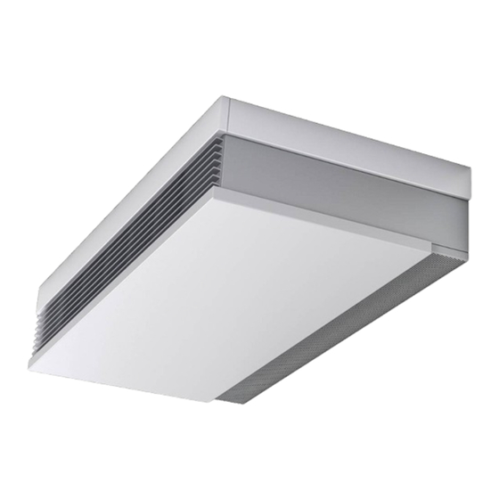
Venkon Assembly, installation and operating instructions Construction and function Overview Fig. 1: Venkon at a glance (example of ceiling model) Condensation pump AC or EC fan Pipework Condensation tray Valve condensation tray Control in the electrical housing (e.g. C1 control) Water connections Heat exchanger Actuator Casing... -
Page 15: Wear Parts List
Venkon Assembly, installation and operating instructions Wear parts list Figure Article Properties Suitable for Art. no. Model 61: 14869BB0102 Model 63: 14869BB0302 Replacement filter 1 no. Venkon AC and EC with frame Model 66: 14869BB0602 Model 67: 14869BB0702 Model 61: 14869BB0105 Model 63: 14869BB0305 Spare filter eP- 1 no. -
Page 16: Installation And Wiring
Venkon Assembly, installation and operating instructions Installation and wiring Definition of the connection side Example of ceiling installation, connection on left Example of ceiling installation, connection on right Fig. 2: Ceiling-mounted, connection on left and right Example of wall installation, connection on left Example of wall installation, connection on right Fig. 3: Wall-mounted, connection on left and right... -
Page 17: Requirements Governing The Installation Site
Venkon Assembly, installation and operating instructions Requirements governing the installation site Only install and assemble the unit if the following conditions are met: Make sure that the wall/ceiling is sufficiently load-bearing to take the weight of the unit (Chapter 4 “Technical data”... -
Page 18: Minimum Clearances
Venkon Assembly, installation and operating instructions Minimum clearances Air outlet area* *The air outlet area needs to be completely barrier-free to guarantee the free circulation of air! There Example of basic unit, wall-hanging (without casing) needs to be a 50 mm freely accessible clearance above the casing to be able to remove the casing. -
Page 19: Installation
Venkon Assembly, installation and operating instructions Installation 2 people are needed to install the unit. CAUTION! Risk of injury from sharp metal housing! The inner metal of the casing can have sharp edges. Wear suitable protective gloves. IMPORTANT NOTE! Horizontal installation of units! Ensure when suspending the units that they are completely horizontal to ensure proper operation! IMPORTANT NOTE! Avoid draughts! -
Page 20: Installation Of Basic Unit
Venkon Assembly, installation and operating instructions 6.4.1 Installation of basic unit 1 There is no need for EC1M control with electromechanical or external control model. Dimensions in brackets = model with cassette filter ePM10>50% (M5) / ePM1> 50% (F7) Example of basic unit EC, wall-mounted version, 2-pipe Keyhole detail 1 There is no need for EC1M control with electromechanical or external... - Page 21 Venkon Assembly, installation and operating instructions B (Distance of suspen- A (Width of basic unit) C (Rear wall) D (Outlet opening) sion points) Model 61 Model 63 Model 66 1375 1310 1340 1181 Model 67 1725 1660 1690 1531 Tab. 4: Dimensions of basic unit Note the Minimum clearances [} 18] when installing the basic units! Highlight the dimensions and clearances of the key holes on the wall or ceiling as per the table, drill the holes and use appropriate fixing materials to install the basic unit.
-
Page 22: Installation Of Casing
Venkon Assembly, installation and operating instructions 6.4.2 Installation of casing Casing overview Casing, wall-mounted, without inlet grille Casing, wall-mounted, with inlet grille Casing, free-standing, with inlet grille and rear panel Casing, ceiling-mounted, with inlet grille Fig. 6: Overview of casings Model 61 Model 63 1200 1180... - Page 23 Venkon Assembly, installation and operating instructions General information on casings Casings are factory-fitted as standard. Casings for wall-mounted and ceiling-mounted models are installed and dismantled in the same way. Always remove the casing ahead of maintenance work (apart from filter replacement). Dismantling/installing the air inlet grille With casings with air inlet grille, remove the grille from the casing before installation and dismantling as the casing can-...
- Page 24 Venkon Assembly, installation and operating instructions Press the casing upwards and insert the retaining tabs into the slots of the main support panels of the basic unit. Fig. 9: Fold up the casing and press in place Screw the casing to the basic unit with 2 countersunk screws. After screwing the casing in place refit he air inlet grille [} 000].
-
Page 25: Installing The Sheet Steel Accessories
Venkon Assembly, installation and operating instructions Changing the air outlet direction To change the air outlet direction, loosen the 2 screws, turn the air outlet grille around 180° and reattach it to the basic unit. Fig. 12: Standard (left) and alternative (right) air outlet direction 6.4.3 Installing the sheet steel accessories Overview, air-side sheet steel accessories Fig. 13: Diagram of arrangement of sheet steel accessories for ceiling-mounted units... - Page 26 Venkon Assembly, installation and operating instructions Figure Description Dimensions [mm] 2 0 0 1375 1725 1 6 0 Internal air grille 2 0 0 1333 1683 1 6 0 1320 1670 90° duct bend 1280 1630 1320 1670 Flexible connector 1280 1630 1320...
- Page 27 Venkon Assembly, installation and operating instructions Figure Description Dimensions [mm] 1320 1670 Outlet box with primary air connection 1280 1630 1370 1720 Outlet box with hotel air opening 1333 1683 1370 1720 Discharge box with primary air connection and hotel air opening 1333 1683...
-
Page 28: Installation
Venkon Assembly, installation and operating instructions Figure Description Dimensions [mm] Ø158 Ceiling swirl diffuser DN180, including clamping flange Outlet Ø 180 mm for installation in suspended ceilings, white painted, for Flexible pipe Ø 158 mm connection to flexible pipe Ø 158 mm Ø280 Tab. 5: Air-side sheet steel accessories Frame connection dimensions... -
Page 29: Connection To The Pipe Network
Venkon Assembly, installation and operating instructions 6.5.1 Connection to the pipe network The flow and return connections are located as standard on the left side of the unit, seen from the front panel. Route the pipes so that no mechanical stresses are transferred to the heat exchanger and that the unit can be accessed with ease for maintenance and repair work. -
Page 30: Sealing The Pipework To The Valve Condensation Tray
Venkon Assembly, installation and operating instructions 6.5.2 Sealing the pipework to the valve condensation tray Proceed as follows when using the valve condensation tray to collect condensation from the valves: Fit diffusion-tight insulation to the pipe from below through the opening of the valve condensation tray to the top edge. -
Page 31: Overview Of Valve Kits
Venkon Assembly, installation and operating instructions 6.5.3 Overview of valve kits Accessories for recirculating air basic unit, water-side, factory-fitted to the basic unit Water connection on Art. no. 2-pipe model with ad- left 14863BBL2*2A Fits all models, com- justable 2-way valve binable control: -00M, with return shut-off Water connection on... -
Page 32: Connection Of 2-Way Valve Kit
Venkon Assembly, installation and operating instructions 6.5.4 Connection of 2-way valve kit 2-way valve kit, wall-mounted, 4-pipe, connection side 2-way valve kit, wall-mounted, 2-pipe, connection on left side on left Front view Front view Side view Side view Rear wall Rear wall View from below View from below... -
Page 33: Connection Of 3-Way Valve Kit
Venkon Assembly, installation and operating instructions 6.5.5 Connection of 3-way valve kit 3-way valve kit, wall-mounted, 4-pipe, connection side 3-way valve kit, wall-mounted, 2-pipe, connection on left side on left Front view Front view Side view Side view Rear wall Rear wall View from below View from below... -
Page 34: Connection Of Differential Pressure-Dependent Valve Kit
Venkon Assembly, installation and operating instructions 6.5.6 Connection of differential pressure-dependent valve kit Valve kit differential pressure-independent, wall- Valve kit differential pressure-independent, wall- mounted, 2-pipe, connection side on left mounted, 4-pipe, connection side on left Front view Front view Side view Side view Rear wall Rear wall... -
Page 35: Condensation Connection
Venkon Assembly, installation and operating instructions 6.5.7 Condensation connection 6.5.7.1 Condensation drain with natural gradient It is essential that a condensation drain is connected and appropriate fixed to a Venkon condensation drain connector (drain size 15 mm). Ensure that the gradient is at least 1 cm/m, without restrictions and without rising sections of pipe (in accord- ance with DIN EN 12056: formerly DIN 1986-100) to ensure the drainage of condensation from the basic unit. - Page 36 Venkon Assembly, installation and operating instructions Condensate drain (accessory) Drainage of condensation from the condensation pump has to be provided along a natural gradient with an adequate cross-section (minimum 1/2"). Increase the cross-section of the line with longer condensation lines. Check whether the condensation line needs to be insulated to prevent the build-up of condensation along the line.
- Page 37 Venkon Assembly, installation and operating instructions Connecting the Condensate Pump Push the suction hose as far as it will go and fix in place with a cable tie to prevent the pump from running dry. Cable tie Suction connection Condensation pump Suction hose Fig. 25: Fixing the suction hose Supply power and wire alarm contact (separate cable with plug) as per the wiring diagram.
-
Page 38: Electrical Wiring
Venkon Assembly, installation and operating instructions Electrical wiring IMPORTANT NOTE! Condensation formation in the cooling unit! In the event of on-site valve control, the cooling valve must be closed when the fans are switched off. Maximum electrical rating values Venkon AC, electromechanical model (*00M / *01M) Model Number of fans Nominal voltage... -
Page 39: Electromechanical Control, Venkon Ac
Venkon Assembly, installation and operating instructions Electromechanical control, Venkon AC 7.2.1 Connection (*00M or 01M), Venkon AC Fig. 27: Position of junction boxes, electromechanical control Electromechanical control Condensation monitor The junction box for electromechanical control (AC and EC) as well as the junction box for the condensation monitor can be electrically installed separately from the side panel of the ba- sic unit by Velcro fitting. - Page 40 Venkon Assembly, installation and operating instructions Description of wiring Factory-fitted actuators are wired to the terminal. If no valve actuators are factory-fitted, support terminals are available for on-site valve actuators. The AC fans used can be controlled between 5 stages via switched voltage terminals 230 V~, 50 Hz. Control version *00M: The built-in thermal contact automatically switches off the fan when it heats up impermissibly and switches it on when it cools down again.
-
Page 41: Cabling, Venkon Ac (*A00M), Control By Room Thermostat Type 148916
Venkon Assembly, installation and operating instructions 7.2.2 Cabling, Venkon AC (*A00M), control by room thermostat type 148916... -
Page 42: Cabling, Venkon Ac (*A00M), Control By Room Thermostat Type 148916, With Condensation Monitor
Venkon Assembly, installation and operating instructions 7.2.3 Cabling, Venkon AC (*A00M), control by room thermostat type 148916, with condensation monitor... -
Page 43: Cabling, Venkon Ac (*A00M), Control By Room Thermostat Type 148915/148918/148917
Venkon Assembly, installation and operating instructions 7.2.4 Cabling, Venkon AC (*A00M), control by room thermostat type 148915/148918/148917... -
Page 44: Cabling, Venkon Ac (*A00M), Control By Room Thermostat Type 148915/148918/148917, With Con
Venkon Assembly, installation and operating instructions 7.2.5 Cabling, Venkon AC (*A00M), control by room thermostat type 148915/148918/148917, with condensation monitor... -
Page 45: Electromechanical Control, Venkon Ec
Venkon Assembly, installation and operating instructions Electromechanical control, Venkon EC 7.3.1 Connection (*00M or 01M), Venkon EC The junction box for electromechanical control (AC and EC) as well as the junction box for the condensation monitor can be electrically installed separately from the side panel of the ba- sic unit by Velcro fitting. - Page 46 Venkon Assembly, installation and operating instructions Note these points in the following wiring diagrams for Venkon EC with electromechanical control: Comply with the details on type of cable and cabling taking into consideration VDE 0100. None *: NYM-J. The requisite number of wires including fuse is stated on the cable. Cross-sections are not indicated as the cable length is involved in the calculation of the cross-section.
-
Page 47: Cabling, Venkon Ec (*00M Or 01M), Control By Climate Controller 30155
Venkon Assembly, installation and operating instructions 7.3.2 Cabling, Venkon EC (*00M or 01M), control by Climate Controller 30155... -
Page 48: Cabling, Venkon Ec (*00M Or 01M), Control By Climate Controller 30155, With Condensation Monitor
Venkon Assembly, installation and operating instructions 7.3.3 Cabling, Venkon EC (*00M or 01M), control by Climate Controller 30155, with condensation monitor... -
Page 49: Cabling, Venkon Ec (*00M Or 01M), Control By Climate Controller 30256
Venkon Assembly, installation and operating instructions 7.3.4 Cabling, Venkon EC (*00M or 01M), control by Climate Controller 30256... -
Page 50: Cabling, Venkon Ec (*00M Or 01M), Control By Climate Controller 30256, With Condensation Monitor
Venkon Assembly, installation and operating instructions 7.3.5 Cabling, Venkon EC (*00M or 01M), control by Climate Controller 30256, with condensation monitor... -
Page 51: Cabling, Venkon Ec (*00M Or 01M), Control By Climate Controller Type 148941/148942
Venkon Assembly, installation and operating instructions 7.3.6 Cabling, Venkon EC (*00M or 01M), control by Climate Controller Type 148941/148942 Support clamp on site... -
Page 52: Cabling, Venkon Ec (*00M Or 01M), Control By Climate Controller Type 148941/148942, With Condens
Venkon Assembly, installation and operating instructions 7.3.7 Cabling, Venkon EC (*00M or 01M), control by Climate Controller Type 148941/148942, with condensation monitor Support clamp on site... -
Page 53: Cabling, Venkon Ec (*00M Or 01M), Control By Ddc/Bms
Venkon Assembly, installation and operating instructions 7.3.8 Cabling, Venkon EC (*00M or 01M), control by DDC/BMS Unit 2 condensation alarm Contact open = alarm (alarm = close cooling valve) Unit 2 motor fault Contact closed = fault Unit 1 condensation alarm Contact open = alarm (alarm = close cooling valve) Unit 1 motor fault... -
Page 54: Kacontrol (*C1)
Venkon Assembly, installation and operating instructions KaControl (*C1) 7.4.1 KaController installation Fig. 32: Installation of flush-mounted back box Electrical wiring Connect the KaController to the nearest KaControl unit in line with the wiring diagram. The maximum bus length between the KaController and the KaControl master unit is 30 m. -
Page 55: Connection (*C1)
Venkon Assembly, installation and operating instructions 7.4.2 Connection (*C1) General information Route all low voltage cables along the shortest route. Ensure that low-voltage and power cables are separated, using metal partitions on cable harnesses. Wrong! Use only shielded cables as low-voltage and bus cables. Star-shaped wiring of the bus lines. - Page 56 Venkon Assembly, installation and operating instructions Description of wiring Units configured for operation with KaControl are fully wired and fitted with all electrical parts ready for connection (with the exception of optional accessories). The speed of the EC fans are controlled by a 0-10 V DC signal from the KaControl. The”intelligent” motor electronics de- tects any possible motor fault and automatically switch the fan off.
- Page 57 Venkon Assembly, installation and operating instructions Note these points in the following wiring diagrams for Venkon EC with KaControl: Comply with the details on type of cable and cabling taking into consideration VDE 0100. None *: NYM-J. The requisite number of wires including fuse is stated on the cable. Cross-sections are not indicated as the cable length is involved in the calculation of the cross-section.
-
Page 58: Cabling, Venkon Ec, Kacontrol (*C1*), Control By Kacontroller
Venkon Assembly, installation and operating instructions 7.4.3 Cabling, Venkon EC, KaControl (*C1*), control by KaController... -
Page 59: Cabling, Venkon Ec, Kacontrol (*C1*), Control By In Situ 0-10 V Dc Signal
Venkon Assembly, installation and operating instructions 7.4.4 Cabling, Venkon EC, KaControl (*C1*), control by in situ 0-10 V DC signal 4-pipe cooling 2-pipe heating/ cooling Note internal resistance of unit! 4-pipe heating Note internal resistance of unit! -
Page 60: Pre-Commissioning Checks
Venkon Assembly, installation and operating instructions Pre-commissioning checks Check before initial commissioning whether all necessary conditions have been met so that the unit can function safely and properly. Structural tests Remove air outlet protection from the outlet air area. Remove protective film from the intake area. Check that the unit is securely standing and fixed. - Page 61 Venkon Assembly, installation and operating instructions Condensation water connection Check the condensation drain and operation of the alarm signal on the condensation pump. Check whether the cooling valve switches off in the event of an alarm signal. Check whether the unit is connected leak-free to the on-site condensation connection. Check whether the waste water lines are clean and have a sufficient gradient.
-
Page 62: Operation
Venkon Assembly, installation and operating instructions Operation Operation of electromechanical control Controls, Venkon AC Room thermostat, type 196000148915/ 196000148918/ 196000148917 Electronic room thermostat with 3-stage switch for 2-pipe applications, surface- mounted wall mounting on a flush-mounted box in visually unobtrusive design. Parallel operation of 2 units is possible. - Page 63 Venkon Assembly, installation and operating instructions Controls, Venkon EC Room thermostat type 196000030155 Electronic room thermostat with 3-stage Automatic function for 2- and 4- pipe applications, surface-mounted wall mounting on a flush-mounted box in visually unobtrusive design Simple operation using a large dial for temperature setting with mechanical range limitation of the temperature setpoint, operating mode selector switch: Standby, Manual fan, Automatic an, 3-stage switch to pre-select fan speed when operating mode selector switch is in the “Manual fan”...
- Page 64 Venkon Assembly, installation and operating instructions Climate controller, white, type 196000148941 For 2- and 4-pipe applications, surface-mounted wall mounting on a flush- mounted box in visually unobtrusive design with 2.5” :CD display and high- quality glass finish with capacitive keys Automatic LED backlight Parametrisable language: German or English Timer program with 3 time channels, each with 4 switchover points...
- Page 65 Venkon Assembly, installation and operating instructions Climate controller, white, type 196000148943 With Modbus interface For 2- and 4-pipe applications, surface-mounted wall mounting on a flush- mounted box in visually unobtrusive design with 2.5” :CD display and high- quality glass finish with capacitive keys Automatic LED backlight Parametrisable language: German or English Timer program with 3 time channels, each with 4 switchover points...
-
Page 66: Operation Of The Kacontroller
Venkon Assembly, installation and operating instructions Operation of the KaController The following information is limited to the key content on the operation of the KaController and KaControl system. More in- formation is included separately in the KaControl SmartBoard user manual. 9.2.1 Function keys, display elements All menus can be selected and set using the navigator dial. - Page 67 Venkon Assembly, installation and operating instructions KaController, black without function keys (one-button opera- tion) type 3210006 1. Display with LED background lighting 2. Navigator dial Change settings Call up menus Fig. 46: KaController black, type 3210006 The symbols shown on the display depend on the application (2-pipe, 4-pipe etc.) and the parameters set. Fig. 47: Display Display of setpoint room temperature Current time...
-
Page 68: Maintenance
Venkon Assembly, installation and operating instructions Maintenance 10.1 Securing against reconnection DANGER! Risk of death by unauthorised or uncontrolled restart! Unauthorised or uncontrolled restarting of the equipment can result in serious injury or death. Before restarting, ensure that all safety devices are fitted and working properly and that there is no haz- ard to humans. -
Page 69: Maintenance Work
Venkon Assembly, installation and operating instructions 10.3 Maintenance work 10.3.1 Replacing the filter. CAUTION! Risk of injury from sharp metal housing! The inner metal of the casing can have sharp edges. Wear suitable protective gloves. Turn latches (left and right) downwards using a flat-blade screwdriver. Important: With units with casing with air inlet grille, the grille needs to be dis- mantled before changing the filter (Installation of casing [} 000]). - Page 70 Venkon Assembly, installation and operating instructions Undo 2 screws and remove the air outlet grille. Fig. 50: Loosen screws Remove 2 screws in casing. Fig. 51: Remove the screws Raise the casing to remove the tabs from the basic unit. Fig. 52: Lift the casing tabs from the basic unit Lower the casing and pull it so that the mounting brackets come our of the pivot bolt.
-
Page 71: Cleaning The Main Condensation Tray
Venkon Assembly, installation and operating instructions 10.3.3 Cleaning the main condensation tray Remove 4 screws. IMPORTANT NOTE! Re-use rubber washers. When screwing on the main condensation tray, it is essential that you use the rubber washers to guarantee a good seal. Fig. 54: Dismantling the main condensation tray (ceiling model) Remove the main condensation tray downwards and forwards. -
Page 72: Cleaning The Valve Condensation Tray
Venkon Assembly, installation and operating instructions 10.3.4 Cleaning the valve condensation tray Dismantle and clean the valve condensation tray. Fig. 58: Dismantle the valve condensation tray (ceiling model) Clean the valve condensation tray. Fig. 59: Valve condensation tray (wall model) 10.3.5 Cleaning the float switch Use pliers to loosen the wire clip, pull it back and remove the hose. -
Page 73: Clean The Inside Of The Unit
Venkon Assembly, installation and operating instructions Loosen the screw on the retaining plate and remove the retaining plate with the float switch fitted. Carefully remove the black hose bend from the underside of the valve condensation tray. Fig. 61: Dismantling the float switch Remove the cover and clean the open float switch. -
Page 74: Faults
Venkon Assembly, installation and operating instructions Faults The following chapter describes possible causes of faults and the work needed to rectify them. Should faults occur frequently, shorten the maintenance intervals in line with the actual loading on the unit. Contact the manufacturer with any faults that cannot be rectified using the following information Behaviour in the event of faults The following applies: 1. -
Page 75: Kacontrol Faults
Venkon Assembly, installation and operating instructions Fault Possible cause Remedy Clean and/or replace impeller. Please make sure Rotating parts unbalanced that no balancing clips are removed during cleaning. Fan dirty. Clean dirt from fan. Heat exchanger dirty. Clean dirt from Heat exchanger. 11.2 KaControl faults Code Alarms... -
Page 76: List Of Kacontrol Parameters
Venkon Assembly, installation and operating instructions List of KaControl parameters 12.1 Venkon parameter list Parameter Function Standard Min. Max. Unit Venkon P000 Software version P001 Base setpoint for setpoint entry ± 3K °C P002 Switching on / off hysteresis for valves K/10 P003 Neutral zone in a 4-pipe system (only in automatic mode) - Page 77 Venkon Assembly, installation and operating instructions Parameter Function Standard Min. Max. Unit Venkon Time that the fan runs on after change of operating mode P035 to stage 1 P036 Type of setpoint setting P037 Display P038 Lock/disable function on control unit P039 Function of digital output V2 (in 2-pipe system) P040...
- Page 78 Venkon Assembly, installation and operating instructions Parameter Function Standard Min. Max. Unit Venkon P075 Serial address of Slave 5 P076 Serial address of Slave 6 P077 Serial address of Slave 7 P078 Serial address of Slave 8 P079 Serial address of Slave 9 P080 Serial address of Slave 10 P081...
-
Page 79: Kacontroller Parameter List
Venkon Assembly, installation and operating instructions Parameter Function Standard Min. Max. Unit Venkon P118 On delay time P119 Off delay time P120 reserved P121 reserved P122 Relative fan speed increase via contact P123 Maximum valve running time P124 Minimum P + I output variation for valve motion (0 to 10) P125 reserved P126... - Page 80 Venkon Assembly, installation and operating instructions Para- Function Standard Min. Max. Unit Comment meter Interval of setpoint setting 0 = Automatic setting depending on t011 PCB (parameterisable, freely programmable) 1 = Increment of 1℃ (parametrisable PCBs) 2 = Increment of 0.5 ℃ (freely programmable PCBs) t012 Date/Time setting: Year t013...
-
Page 81: Certificates
Venkon Assembly, installation and operating instructions Certificates... -
Page 84: Table
Venkon Assembly, installation and operating instructions Table Tab. 1 Limits of operation..............................8 Tab. 2 Operating voltage..............................8 Tab. 3 Water quality ................................8 Tab. 4 Dimensions of basic unit............................21 Tab. 5 Air-side sheet steel accessories..........................25 Tab. 6 * Water connections............................... - Page 88 www.kampmanngroup.com/hvac/products/fan-coils/ venkon...