Table of Contents
Advertisement
B B
D D
T T
S S
2 2
0 0
0 0
B B
D D
T T
S S
2 2
0 0
BEFORE YOU CALL, HAVE THE FOLLOWING INFORMATION AVAILABLE, CATALOG No., TYPE No., AND DATE CODE . IN MOST CASES, A
BLACK & DECKER REPRESENTATIVE CAN RESOLVE THE PROBLEM OVER THE PHONE. IF YOU HAVE A SUGGESTION OR CO
SAVE THIS MANUAL FOR FUTURE REFERENCE.
VEA EL ESPAÑOL EN LA CONTRAPORTADA.
POUR LE FRANÇAIS, VOIR LA COUVERTURE ARRIÈRE.
INSTRUCTIVO DE OPERACIÓN, CENTROS DE SERVICIO Y
PÓLIZA DE GARANTÍA. ADVERTENCIA: LÉASE ESTE
INSTRUCTIVO ANTES DE USAR EL PRODUCTO.
1 1
0 0
I I
N N
C C
H H
0 0
1 1
0 0
I I
N N
C C
H H
INSTRUCTION MANUAL
T
T
HANK
YOU
FOR
HANK
YOU
FOR
G
.B
G
.B
O
T
O
WWW
LACKAND
O
T
O
WWW
LACKAND
T
O
REGISTER
T
O
REGISTER
BEFORE RETURNING THIS PRODUCT
FOR ANY REASON PLEASE CALL
GIVE US A CALL. YOUR FEEDBACK IS VITAL TO BLACK & DECKER.
( (
2 2
5 5
4 4
M M
M M
( (
2 2
5 5
4 4
M M
M M
B
&
B
&
CHOOSING
LACK
CHOOSING
LACK
D
.
/N
D
.
/N
ECKER
COM
ECKER
COM
YOUR
NEW
PRODUCT
YOUR
NEW
PRODUCT
1-800-544-6986
) )
T T
A A
B B
L L
E E
) )
T T
A A
B B
L L
E E
D
!
D
!
ECKER
ECKER
O
O
EW
WNER
EW
WNER
.
.
S S
A A
W W
S S
A A
W W
MMENT,
Advertisement
Table of Contents

Related Manuals for Black & Decker 90528116


Summary of Contents for Black & Decker 90528116
-
Page 1: Instruction Manual
HANK HANK BEFORE YOU CALL, HAVE THE FOLLOWING INFORMATION AVAILABLE, CATALOG No., TYPE No., AND DATE CODE . IN MOST CASES, A BLACK & DECKER REPRESENTATIVE CAN RESOLVE THE PROBLEM OVER THE PHONE. IF YOU HAVE A SUGGESTION OR CO GIVE US A CALL. -
Page 2: Table Of Contents
TABLE OF CONTENTS IMPORTANT SAFETY INSTRUCTIONS ............2 SAFETY GUIDELINES . -
Page 3: Safety Guidelines
SAFETY GUIDELINES - DEFINITIONS It is important for you to read and understand this manual. The information it contains relates to protecting YOUR SAFETY and PREVENTING PROBLEMS. The symbols below are used to help you recognize this information. DANGER: Indicates an imminently hazardous situation which, if not avoided, will result in death or serious injury. WARNING: Indicates a potentially hazardous situation which, if not avoided, could result in death or serious injury. -
Page 4: Important Safety Instructions
WARNING: READ ALL INSTRUCTIONS BEFORE OPERATING PRODUCT. FAILURE TO FOLLOW ALL INSTRUCTIONS LISTED BELOW MAY RESULT IN ELECTRIC SHOCK, FIRE AND OR SERIOUS INJURY. 1. FOR YOUR OWN SAFETY, READ THE INSTRUCTION MANUAL BEFORE OPERATING THE MACHINE. Learning the machine’s application, limitations, and specific hazards will greatly minimize the possibility of accidents and injury. -
Page 5: Additional Specific Safety Rules
B. keeping rip fence parallel to the saw blade. C. using saw blade guard and spreader for every possible operation, including all through sawing. D. pushing the workpiece past the saw blade prior to release. E. never ripping a workpiece that is twisted or warped, or does not have a straight edge to guide along the fence. -
Page 6: Power Connections
POWER CONNECTIONS A separate electrical circuit should be used for your machines. This circuit should not be less than #12 wire and should be protected with a 20 Amp time lag fuse. If an extension cord is used, use only 3-wire extension cords which have 3-prong grounding type plugs and matching receptacle which will accept the machine’s plug. -
Page 7: Functional Description
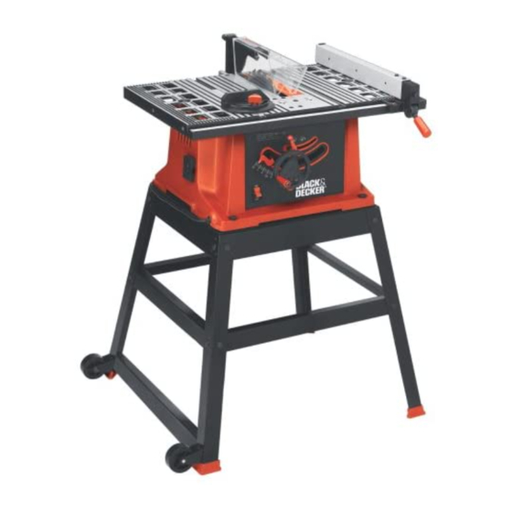
FOREWORD Model BDTS200 is a 10 inch Table Saw designed to give high quality performance with depth of cut capacity up to 3 inches (76mm) at 90° and 2 inches (51mm) at 45° for clean cutting of standard stock sizes. - Page 8 Fig. 4 Stand Hardware 1. Leg (4) (2 with holes at base for attaching wheel bracket and brace) 2. 3/8 inchFlat Washer for Mounting Saw to Stand & for Assembling Stand (24) 3. Foot (4) 4. M8x1.25 Hex Nut for Mounting Saw to Stand &...
-
Page 9: Assembly
ELEVATING AND SUPPORTING SURFACES FOR A SAW WITH NO STAND WARNING: THE SAW MUST BE PROPERLY SECURED TO A SUPPORTING SURFACE. ALSO, FAILURE TO PROVIDE A SAWDUST FALL-THROUGH AND REMOVAL HOLE WILL ALLOW SAWDUST TO BUILD UP AROUND THE MOTOR, CAUSING A POSSIBLE FIRE HAZARD AND/OR MOTOR DAMAGE. -
Page 10: Miter Gauge
(E) secured to the miter gauge holder. Attach the miter gauge holder (A) Fig. 7 to the left side of the saw cabinet using the four M4x.2x10mm screws (B) Fig. 8, and 3/16 inch flat washers (C) from inside of the saw cabinet. -
Page 11: Assembling Stand
3. Stand the saw upright, as shown in Fig. 13 (Saw is shown fully assembled here). 4. Push down on top of the saw so that the legs of the stand adjust to the surface of the floor. Tighten all hardware securely. - Page 12 WARNING: PROPERLY ALIGN THE BLADE GUARD AND SPLITTER ASSEMBLY WITH THE SAW BLADE TO PREVENT KICKBACK. 1. Position the blade 90 degrees to the table and lock in place. 2. Fasten the splitter support bracket (A) Fig. 17 to the...
- Page 13 Locate the 1/4-20x2 inch hex head screw (G) Fig. 18. Place the 1/4 inch internal tooth lockwasher (O) M6.4 flat washer (P) and the 1/4 inch external tooth lockwasher (R) on the screw (G). Position the recessed end (E) Fig. 19 of the splitter bracket (B) against the end of the pivot rod (F), and fasten using the assembly in STEP 3.
-
Page 14: Assembling Rip Fence
Fig. 27 against the cam (D). 3. The rip fence is usually set up on the right hand side of the saw table. Lift the lock handle (B) Fig. 28 and position the fence on the table. Push down on the handle (B) Fig. -
Page 15: Operation
STARTING AND STOPPING SAW The on/off switch (A) Fig. 29 is located on the front of the saw cabinet. To turn the saw “ON”, move the switch (A) up to the “ON” position. To turn the saw “OFF”, move the switch (A) down to the “OFF” position. -
Page 16: Blade Tilt Adjustment
(A) MUST BE LOCKED DURING ALL CUTTING OPERATIONS. 90 AND 45 DEGREE POSITIVE STOP ADJUSTMENTS Your saw is equipped with positive stops for rapid and accurate positioning of the saw blade at 90 and 45 degrees to the table. WARNING: DISCONNECT MACHINE FROM POWER SOURCE. -
Page 17: Table Insert Adjustment
3. The saw blade is set parallel to the miter gauge slot at the factory. The fence must be parallel to the miter gauge slot to do accurate work and to prevent kickback when ripping. -
Page 18: Adjusting Blade Parallel To Miter Gauge Slots
1. Raise the blade to its highest position and adjust the blade so that it is 90 degrees to the table. 2. Select a tooth on the saw blade that is set to the left. Mark this tooth with a pencil or marker. -
Page 19: Changing The Blade
WARNING: DISCONNECT THE MACHINE FROM THE POWER SOURCE. USE ONLY 10 INCH DIAMETER SAW BLADES RATED FOR 4700 RPM OR HIGHER. USE ONLY SAW BLADES WITH 5/8 INCH ARBOR HOLES. 1. NOTE: One 7/8 inch wrench is supplied with the saw for changing the saw blade. - Page 20 (B) Fig. 42B can be clamped to the fence and used as a cut-off gage as shown in Fig. 42B. It is important that this block of wood always be positioned in front of the saw blade as shown. Once the cut-off length is determined, secure the fence and use the miter gage to feed the work into the cut.
- Page 21 When ripping boards longer than three feet, use a work support at the rear of the saw to keep the workpiece from falling off the saw table. 3. If the ripped work is less than 6 inches wide, a push stick should always be used to complete the feed, as shown in Fig.
- Page 22 2. Attach the dado head set (D) Fig. 51, to the saw arbor. NOTE: THE OUTSIDE ARBOR FLANGE CAN NOT BE USED WITH THE DADO HEAD SET, TIGHTEN THE ARBOR NUT AGAINST THE DADO HEAD SET BODY.
-
Page 23: Constructing A Push Stick
CONSTRUCTING A PUSH STICK When ripping work less than 4 inches wide, a push stick should be used to complete the feed and could be easily made from scrap material by following the pattern shown in Fig. 53. -
Page 24: Constructing A Featherboard
CONSTRUCTING A FEATHERBOARD Fig. 54, illustrates dimensions for making a typical featherboard. The material which the featherboard is constructed of, should be a straight piece of wood that is free of knots and cracks. Featherboards are used to keep the work in contact with the fence and table, as shown in Fig. -
Page 25: Troubleshooting
TROUBLESHOOTING BE SURE TO FOLLOW SAFETY RULES AND INSTRUCTIONS TROUBLE! SAW WILL NOT START WHAT’S WRONG? 1.Saw not plugged in. 2.Fuse blown or circuit breaker tripped. 2.Replace fuse or reset 3.Cord damaged. 4.Brushes worn out. TROUBLE! SAW MAKES UNSATISFACTORY CUTS WHAT’S WRONG? -
Page 26: Maintenance
MAINTENANCE KEEP MACHINE CLEAN Periodically blow out all air passages with dry compressed air. All plastic parts should be cleaned with a soft damp cloth. NEVER use solvents to clean plastic parts. They could possibly dissolve or otherwise damage the material. WARNING: Wear ANSI Z87.1 safety glasses while using compressed air. -
Page 27: Spanish
ERCI ERCI ISITEZ ISITEZ POUR ENREGISTRER POUR ENREGISTRER AVANT DE RETOURNER CE PRODUIT POUR QUELQUE RAISON QUE CE SOIT, AVANT D’APPELER, AYEZ EN MAIN LE N° DE CATALOGUE ET LE CODE DE DATE. DANS LA PLUPART DES CAS, UN REPRÉSENTANT DE BLACK & TÉLÉPHONE. - Page 28 LIGNES DIRECTRICES EN MATIÈRE DE SÉCURITÉ — DÉFINITIONS Il est important que vous lisiez et compreniez ce mode d’emploi. Les informations qu’il contient concernent VOTRE SÉCURITÉ et visent à ÉVITER TOUT PROBLÈME. Les symboles ci-dessous servent à vous aider à reconnaître cette information.
- Page 29 RÈGLES GÉNÉRALES DE SÉCURITÉ AVERTISSEMENT : LIRE TOUTES LES DIRECTIVES AVANT D’UTILISER LE PRODUIT. NÉGLIGER DE SUIVRE TOUTES LES DIRECTIVES SUIVANTES PEUT ENTRAÎNER DES RISQUES DE CHOCS ÉLECTRIQUES, D’INCENDIE ET/OU DE BLESSURES GRAVES. POUR SA PROPRE SÉCURITÉ, LIRE LE MODE D’EMPLOI AVANT D’UTILISER L’OUTIL.
- Page 30 RÈGLES DE SÉCURITÉ SPÉCIFIQUES SUPPLÉMENTAIRES AVERTISSEMENT : LIRE TOUTES LES DIRECTIVES AVANT D’UTILISER LE PRODUIT. NÉGLIGER DE SUIVRE TOUTES LES DIRECTIVES SUIVANTES PEUT ENTRAÎNER DES RISQUES DE CHOCS ÉLECTRIQUES, D’INCENDIE ET/OU DE BLESSURES GRAVES. 1. NE PAS UTILISER CET OUTIL AVANT qu'il ne soit assemblé...
- Page 31 CONNEXIONS ÉLECTRIQUES Un circuit électrique séparé doit être utilisé pour vos machines. Ce circuit doit utiliser un câble de calibre 12 au minimum et doit être protégé par un fusible temporisé de 20 A. Si vous utilisez une rallonge électrique, n’utiliser que des rallonges à...
-
Page 32: Description Fonctionnelle
RALLONGES ÉLECTRIQUES Utiliser les rallonges appropriées AVERTISSEMENT : S'assurer que la rallonge est en bon état et qu’il s’agit d’une rallonge à 3 fils avec une fiche de mise à la terre à 3 broches et prise de courant compatible avec la fiche de l'appareil. - Page 33 Fig. 4 Quincaillerie pour le socle 1. (4) pattes (dont 2 sont perforées à la base pour la fixation du support de roue et de la traverse) 2. (24) Rondelles plates de 3/8 po (4,8 mm) pou fixer la scie à un socle et assembler le socle 3.
- Page 34 FIXATION DU PORTE-JAUGE À ONGLET DÉBRANCHER L'APPAREIL DE LA SOURCE D’ALIMENTATION. AVERTISSEMENT : Fixer l'attache à ressort (E) fig. 5 du porte-jauge à onglet (A) en utilisant une vis à tête cylindrique de M4x de 0,7 x 10 mm (F), une rondelle à denture extérieure de 3/16 po (4,8 mm), (B) et un écrou hexagonal M4x de 0,7. REMARQUE : l'écrou hexagonal (G) fig.
- Page 35 Localiser la vis à tête hexagonale 1/4-20x2 po (G, fig. 18. Placer la rondelle à denture intérieure de 1/4 po (6,4 mm) (O), la rondelle plate M6.4 (P) et la rondelle à denture extérieure de 1/4 po (6,4 mm) (R) sur la vis (G). Positionner l’extrémité...
- Page 36 RÉGLAGE DE LA HAUTEUR DE LA LAME Pour régler la hauteur de la lame de la scie, tourner le volant (A) fig. 31. Tourner le volant en sens horaire abaisse la lame et le tourner dans le sens antihoraire la relève. RÉGLAGE DE L’INCLINAISON DE LA LAME Pour incliner la lame de la scie, desserrer la poignée de verrouillage (A) fig.
-
Page 37: Changement De La Lame
UTILISATION ET RÉGLAGES DE LA JAUGE À ONGLET Pour le tronçonnage (lame à 90 degrés de la table la jauge à onglet peut être utilisée dans l'une ou l'autre fente sur la table. Pour un tronçonnage en biseau (avec la lame inclinée) utiliser la jauge à onglet dans la fente droite de la table uniquement pour que la lame soit inclinée en s'éloignant de la jauge et de vos mains. - Page 38 UNE DES RÈGLES D'UTILISATION D'UNE SCIE : NE JAMAIS SE SUSPENDRE SUR, NI AVERTISSEMENT : TOUCHER LA PARTIE DE LA PIÈCE À DÉCOUPER. Tenir la pièce supportée, et non la pièce coupée. Le tronçonnage se poursuit jusqu’à ce que la pièce soit coupée en deux, et que la jauge à...
- Page 39 UTILISATION DU PAREMENT EN BOIS AUXILIAIRE FACE AU GUIDE LONGITUDINAL En exécutant certaines coupes spéciales – et si cette opération peut mettre l'accessoire de coupe en contact avec le guide – il faut ajouter un parement en bois (A) fig. 47A, d'un côté du guide longitudinal tel qu'illustré. Le parement en bois se fixe au guide avec des vis en bois à...
- Page 40 FABRICATION D’UNE PLANCHE EN ÉVENTAIL La figure 54 illustre les dimensions utilisées pour la fabrication d’une planche en éventail typique. Utiliser une pièce de bois droite exempte de noeuds et de fissures pour la fabrication de la planche en éventail. Les planches en éventail sont utilisées pour maintenir la pièce en contact avec le guide et la table, comme indiqué...
- Page 41 ACCESSOIRES Les accessoires recommandés pouvant être utilisés avec l’outil sont disponibles auprès de votre distributeur local ou centre de réparation autorisé. Pour tout renseignement concernant les accessoires, composer le : 1-800-544-6986 l’utilisation de tout accessoire non recommandé avec l’outil pourrait s’avérer dangereuse. RÉPARATION Tous les centres de réparation Black &...
- Page 42 MANUAL DE INSTRUCCIONES ¡G ¡G RACIAS RACIAS ANTES DE DEVOLVER ESTE PRODUCTO POR CUALQUIER MOTIVO, LLAME AL ANTES DE LLAMAR, TENGA EL NÚMERO DE CATÁLOGO Y EL CÓDIGO DE FECHA PREPARADOS. EN LA MAYORÍA DE LOS CASOS, UN REPRESENTANTE DE BLACK & DECKER PUEDE RESOLVER EL PROBLEMA POR TELÉFONO. SI DESEA REALIZAR UNA SUGERENCIA O COMENTARIO, LLÁMENOS.
-
Page 43: French
PAUTAS DE SEGURIDAD/DEFINICIONES Es importante para usted leer y entender este manual. La información que lo contiene relaciona a proteger SU SEGURIDAD y PREVENIR los PROBLEMAS. Los símbolos debajo de son utilizados para ayudarlo a reconocer esta información. PELIGRO: Indica una situación de inminente riesgo, la cual, si no es evitada, causará la muerte o lesiones serias. ADVERTENCIA: Indica una situación potencialmente riesgosa, que si no es evitada, podría resultar en la muerte o lesiones serias. -
Page 44: Normas Generales De Seguridad
NORMAS GENERALES DE SEGURIDAD ADVERTENCIA: LEA TODAS LAS INSTRUCCIONES ANTES DE OPERAR EL PRODUCTO. EL INCUMPLIMIENTO DE LAS INSTRUCCIONES ENUMERADAS A CONTINUACIÓN PUEDE PROVOCAR UNA DESCARGA ELÉCTRICA, UN INCENDIO O LESIONES GRAVES. INSTRUCCIONES IMPORTANTES SOBRE SEGURIDAD PARA SU PROPIA SEGURIDAD, LEA EL MANUAL DE INSTRUCCIONES ANTES DE UTILIZAR LA MÁQUINA. - Page 45 REGLAS DE SEGURIDAD ADICIONALES ADVERTENCIA: LEA TODAS LAS INSTRUCCIONES ANTES DE OPERAR EL PRODUCTO. EL INCUMPLIMIENTO DE LAS INSTRUCCIONES ENUMERADAS A CONTINUACIÓN PUEDE PROVOCAR UNA DESCARGA ELÉCTRICA, UN INCENDIO O LESIONES GRAVES. NO UTILICE ESTA MÁQUINA hasta que esté completamente montada e instalada de acuerdo con las instrucciones.
- Page 46 CONEXIONES A LA FUENTE DE ALIMENTACIÓN Debe utilizarse un circuito eléctrico independiente para las máquinas. Este circuito debe tener alambre de no menos del No. 12 y debe estar protegido con un fusible de acción retardada de 20 A. Si se utiliza un cordón de extensión, utilice únicamente cordones de extensión de tres alambres que tengan enchufes de tipo de conexión a tierra con tres terminales y un receptáculo coincidente que acepte el enchufe de la máquina.
-
Page 47: Instrucciones De Funcionamiento
CORDONES DE EXTENSIÓN Utilice cordones de extensión PRECAUCIÓN: apropiados. Asegúrese de que el cordón de extensión esté en buenas condiciones y de que sea un cordón de extensión de tres alambres que tenga un enchufe de tipo de conexión a tierra con tres terminales y un receptáculo coincidente que acepte el enchufe de la máquina. - Page 48 ENSAMBLAJE HERRAMIENTAS DE ENSAMBLAJE REQUERIDAS NINGUNOS PROVISTOS * El destornillador de cruz * 13mm llave de boca ESTIMACIÓN DEL TIEMPO DE ENSAMBLAJE - 60 minutos ELEVAR Y SUPERFICIES SECUNDARIAS PARA UN VIO CON NINGÚN SOPORTE ADVERTENCIA: EL VIO DEBE SER ASEGURADO APROPIADAMENTE A UNA SUPERFICIE SECUNDARIA. TAMBIÉN, USTED DEBE PROPORCIONAR UN HOYO PARA EL SERRÍN PARA CAERSE POR O EL POLVO REUNIRÁ...
- Page 49 ENSAMBLADO DEL PORTADOR DE LA ESCUADRA DE INGLETES ADVERTENCIA: DESCONCTE LA MAQUINA DE LA FUENTE DE ALIMENTACION. 1. Ensamble fig. 5 del (E) del clip de resorte, el (A) del sostenedor de la galga de los ingletes según lo mostrado usando un tornillo de la pista de la cacerola de M4x.7x10mm (F), el (B) de la arandela de cierre del diente del 3/16"...
- Page 50 ENSAMBLADO DEL VOLANTE DE INCLINACION Y ELEVADO DE HOJA Inserte el tornillo de M6x1x55 screw (D) Fig. 14, a través de la agarradera (E) y ensamble la agarradera (E) al volante de mano (A) mediante el roscado del tornillo (D) en el sentido de las manecillas del reloj hacia dentro del volante de mano.
- Page 51 TRASLADO DE LA SIERRA Para trasladar la sierra, tome el lado de la mesa opuesto a las ruedas. Levante apenas la sierra del suelo y empuje la mesa hasta la posición deseada como se muestra. PRECUCI Ó N: No todos los pisos son totalmente uniformes, revise ambas ruedas cada vez que traslade la sierra para asegurarse de que no se traben en el piso cuando la sierra esté...
- Page 52 FUNCIONAMIENTO Y AJUSTES DE LA GUIA DE CORTE A LO LARGO 1. Para mover la guía de corte a lo largo (A) Fig. 35, a lo largo de la mesa, levante la palanca de cierre (B), deslice la guía a la posición deseada en la mesa y empuje la palanca de cierre de la guía (B) hacia abajo para fijar la guía a dicha posición.
-
Page 53: Cambio De La Hoja
CAMBIO DE LA HOJA ADVERTENCIA: DESCONECTE LA MÁQUINA DE LA FUENTE DE ALIMENTACIÓN. UTILICE HOJAS DE SIERRA CON UN DIÁMETRO DE 254 MM (10”) CALIFICADAS PARA 4700 RPM O MAYOR. UTILICE ÚNICAMENTE HOJAS DE SIERRA CON ORIFICIOS PARA MANDRIL DE 16 MM (5/8”). NOTA: Junto con la sierra se suministra una llave de 22,2 mm (7/8") para cambiar la hoja de la sierra. - Page 54 ADVERTENCIA: UNA TOPE-GUIA SIEMPRE SE DEBE UTILIZAR PARA LAS OPERACIONES LA REALIZACIÓN DE CORTES AL HILO. NUNCA REALICE UNA OPERACIÓN QUE LA REALIZACIÓN DE CORTES AL HILO HECHO A PULSO. 1. Arranque el motor y haga avanzar la pieza de trabajo sujetándola hacia abajo y contra el tope-guía. No se sitúe nunca en la línea del corte de la sierra cuando realice cortes al hilo.
- Page 55 ADVERTENCIA: EL CONJUNTO DE PROTECTOR DE LA HOJA Y SEPARADOR NO SE PUEDE UTILIZAR CUANDO SE REALICEN OPERACIONES DE RANURADO Y SE DEBE QUITAR O GIRAR HASTA LA PARTE TRASERA DE LA SIERRA. TAMBIÉN SE DEBEN USAR POSICIONADORES AUXILIARES, DISPOSITIVOS DE FIJACIÓN, PALOS DE EMPUJAR Y TABLAS DE CANTO BISELADO.
- Page 56 DETECCIÓN DE PROBLEMAS ASEGÚRESE DE SEGUIR LAS REGLAS E INSTRUCCIONES DE SEGURIDAD PROBLEMA: LA SIERRA NO ENCIENDE ¿QUÉ SUCEDE? 1.La sierra no está enchufada. 2.Fusible quemado o interruptor automático activado. 3.Cable dañado. 4.Cepillos gastados. PROBLEMA: LA SIERRA REALIZA CORTES NO SATISFACTORIOS ¿QUÉ...
- Page 57 Col. Centro PARA OTRAS LOCALIDADES LLAME AL: (55) 5326 7100 Vea “Herramientas eléctricas (Tools-Electric)” – Páginas amarillas – para Servicio y ventas Cat.No. BDTS200 Form No. 90528116 MONTERREY, N.L. Av. Francisco I. Madero No.831 (81) 8375 2313 Col. Centro PUEBLA, PUE...
- Page 58 NOTES / NOTAS...
- Page 59 NOTES / NOTAS...
- Page 60 NOTES / NOTAS...