Dell Latitude 7220 Service Manual
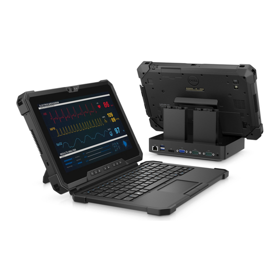
Rugged extreme tablet
Hide thumbs
Also See for Latitude 7220:
- Setup and specifications (22 pages) ,
- User manual (21 pages) ,
- Quick start manual (14 pages)

Related Manuals for Dell Latitude 7220


Summary of Contents for Dell Latitude 7220
- Page 1 Latitude 7220 Rugged Extreme Tablet Service Manual Regulatory Model: T03H Regulatory Type: T03H003...
- Page 2 A WARNING indicates a potential for property damage, personal injury, or death. © 2019 Dell Inc. or its subsidiaries. All rights reserved. Dell, EMC, and other trademarks are trademarks of Dell Inc. or its subsidiaries. Other trademarks may be trademarks of their respective owners.
-
Page 3: Table Of Contents
Contents 1 Working on your tablet........................6 Safety instructions.................................6 Before working inside your tablet..........................6 Safety precautions................................7 Electrostatic discharge—ESD protection........................7 ESD field service kit ................................8 Transporting sensitive components..........................8 After working inside your tablet.............................9 2 Removing and installing components.................... 10 Recommended tools................................ - Page 4 Installing the WWAN card............................36 Microphone...................................37 Removing the microphone............................37 Installing the microphone.............................. 37 Front camera..................................38 Removing the front camera............................38 Installing the front camera............................40 Coin-cell battery.................................. 42 Removing the coin-cell battery............................42 Installing the coin-cell battery............................43 System board..................................44 Removing the system board............................44 Installing the system board............................49 Rear Camera..................................
- Page 5 Updating the Dell BIOS in Linux and Ubuntu environments..................76 Flashing the BIOS from the F12 One-Time boot menu.....................76 System and setup password.............................. 79 Assigning a system setup password........................... 80 Deleting or changing an existing system setup password..................80 4 Troubleshooting..........................81 Enhanced Pre-Boot System Assessment (ePSA) diagnostics..................81 Running the ePSA diagnostics............................81...
-
Page 6: Working On Your Tablet
Damage due to servicing that is not authorized by Dell is not covered by your warranty. Read and follow the safety instructions that came with the product. -
Page 7: Safety Precautions
Due to the increased density of semiconductors used in recent Dell products, the sensitivity to static damage is now higher than in previous Dell products. For this reason, some previously approved methods of handling parts are no longer applicable. -
Page 8: Esd Field Service Kit
Transporting sensitive components When transporting ESD sensitive components such as replacement parts or parts to be returned to Dell, it is critical to place these parts in anti-static bags for safe transport. -
Page 9: After Working Inside Your Tablet
After you complete any replacement procedure, ensure that you connect external devices, cards, and cables before turning on your tablet. CAUTION: To avoid damage to the tablet, use only the battery that is designed for this particular Dell tablet. Do not use batteries that are designed for other Dell tablets. -
Page 10: Removing And Installing Components
Removing and installing components Recommended tools The procedures in this document require the following tools: • Phillips #0 screwdriver • Phillips #1 screwdriver • Philips #2 screwdriver • Plastic scribe NOTE: The #0 screw driver is for screws 0-1 and the #1 screw driver is for screws 2-4. Screw list NOTE: When removing screws from a component, it is recommended to note the screw type, the quantity of screws,... -
Page 11: Batteries
If the battery gets stuck inside your computer as a result of swelling, do not try to release it as puncturing, bending, or crushing a lithium-ion battery can be dangerous. In such an instance, contact Dell technical support for assistance. See www.dell.com/contactdell. -
Page 12: Installing The Batteries
Steps 1. Slide the battery release latch to the unlock position. 2. Slide the latch down to unlock the battery. 3. Lift the battery out of the battery bay. 4. Remove the battery from the tablet. Installing the batteries Prerequisites If you are replacing a component, remove the existing component before performing the installation procedure. -
Page 13: Subscriber Identification Module (Sim) Card
Steps 1. Align the pins on the battery with the connector on the tablet. NOTE: Ensure that the metal pin of the battery is aligned in place. 2. Place the battery into the battery bay until it clicks into place. 3. -
Page 14: Inserting The Usim
About this task The figure indicates the location of the uSIM and provides a visual representation of the removal procedure. Steps 1. Open the uSIM slot cap. 2. Press the uSIM card and slide it out of the slot. NOTE: Use a flat pointed scribe to ease removing the SIM. -
Page 15: Stylus
Steps 1. Insert the uSIM card in the slot until it is locked. 2. Close the uSIM slot cap to initial state. Next steps 1. Install the batteries. 2. Follow the procedure in after working inside your tablet. Stylus Removing the stylus Prerequisites 1. -
Page 16: Installing The Stylus
Steps Slide the stylus upward using the groove on the stylus pen. NOTE: Avoid pulling the stylus with the stretchable thread. The stylus is ready to assist you in using the rugged tablet. Installing the stylus Prerequisites If you are replacing a component, remove the existing component before performing the installation procedure. About this task The figure indicates the location of the stylus and provides a visual representation of the installation procedure. -
Page 17: Display Assembly
Steps Insert the stylus into the slot on the tablet. NOTE: When not in use, avoid hanging the stylus that is detached from its groove. Next steps 1. Follow the procedure in after working inside your tablet. Display assembly Removing the display assembly Prerequisites 1. - Page 18 Removing and installing components...
- Page 19 Removing and installing components...
-
Page 20: Installing The Display Assembly
Steps 1. Place the tablet on a flat and clean surface and remove the 19 (M2.5x5) screws that secure the display assembly to the chassis. 2. Flip the tablet. 3. Using a plastic scribe, gently pry the edges evenly to unlock the plastic clips that secure the display assembly to the chassis. NOTE: Tip of the plastic scribe should be inserted to avoid damage to the seal on the display assembly and to the clips that secure the display assembly to the chassis. - Page 21 About this task The figure indicates the location of the component and provides a visual representation of the installation procedure. Removing and installing components...
- Page 22 Removing and installing components...
-
Page 23: Function Keys
Steps 1. Place the LCD panel by less than 90° and use a plastic scribe to connect the eDP cable to the connector on the system board. 2. Connect the function key cable to the connector on the system board. 3. -
Page 24: Removing The Function Keys
Removing the function keys Prerequisites 1. Follow the procedure in before working inside your tablet. 2. Remove the batteries. 3. Remove the display assembly. About this task The figure indicates the location of the function keys and provides a visual representation of the removal procedure. Steps 1. -
Page 25: Installing The Function Keys
Installing the function keys Prerequisites If you are replacing a component, remove the existing component before performing the installation procedure. About this task The figure indicates the location of the function keys and provides a visual representation of the installation procedure. Steps 1. -
Page 26: Heat Sink
Heat sink Removing the heat-sink Prerequisites 1. Follow the procedure in before working inside your tablet. 2. Remove the batteries. 3. Remove the display assembly. About this task The figure indicates the location of the heat sink and provides a visual representation of the removal procedure. Steps 1. -
Page 27: Installing The Heat-Sink
NOTE: Ensure not to bend the heatsink pipe while removing the heatsink from the SSD. Do not remove the heatsink by pulling on the pipe. Carefully pry the cover from the SSD using a plastic scribe. 2. Lift the heat-sink away from the system board. Installing the heat-sink Prerequisites If you are replacing a component, remove the existing component before performing the installation procedure. -
Page 28: System Fan
Next steps 1. Install the display assembly. 2. Install the batteries. 3. Follow the procedure in after working inside your tablet. System fan Removing the system fan Prerequisites 1. Follow the procedure in before working inside your tablet. 2. Remove the batteries. 3. -
Page 29: Installing The System Fan
3. Remove the four (M2x5) screws that secure the system fan to the system board. 4. Lift the system fan off the system board. Installing the system fan Prerequisites If you are replacing a component, remove the existing component before performing the installation procedure. About this task The figure indicates the location of the system fan and provides a visual representation of the installation procedure. -
Page 30: Solid-State Drive
4. Follow the procedure in after working inside your tablet. Solid-state drive Removing the M.2 2230 solid-state drive Prerequisites 1. Follow the procedure in before working inside your tablet. 2. Remove the batteries. 3. Remove the display assembly. 4. Remove the heat-sink. About this task The figure indicates the location of the M.2 2230 solid-state drive and provides a visual representation of the removal procedure. -
Page 31: Installing M.2 2230 Solid-State Drive
Steps 1. Remove the (M2x3) screw that secures the solid-state drive to the system board. 2. Slide and remove the solid-state drive from the solid-state drive slot on the system board. Installing M.2 2230 solid-state drive Prerequisites If you are replacing a component, remove the existing component before performing the installation procedure. About this task The following image indicates the location of the M.2 2230 solid-state drive and provides a visual representation of the installation procedure:... -
Page 32: Wlan Card
About this task The following image indicates the location of the M.2 2280 solid-state drive and provides a visual representation of the installation procedure: Steps 1. Align the notch on the solid-state drive with the tab on the solid-state drive slot. 2. -
Page 33: Installing The Wlan Card
Steps 1. Remove the screw (M2x3) that secures the WLAN card bracket to the WLAN card. 2. Remove the WLAN card bracket from the WLAN card. 3. Disconnect the antenna cables from the WLAN card. 4. Slide and remove the WLAN card from the WLAN card slot. Installing the WLAN card Prerequisites If you are replacing a component, remove the existing component before performing the installation procedure. - Page 34 Steps 1. Slide the wireless card at an angle into the wireless-card slot. 2. Connect the antenna cables to the WLAN card. The following table provides the antenna-cable color scheme for the WLAN card that is supported by your tablet. Table 2.
-
Page 35: Wwan Card
WWAN card Removing the WWAN card Prerequisites 1. Follow the procedure in before working inside your tablet. 2. Remove the batteries. 3. Remove the display assembly. About this task The figure indicates the location of the WWAN card and provides a visual representation of the removal procedure. Steps 1. -
Page 36: Installing The Wwan Card
Installing the WWAN card Prerequisites If you are replacing a component, remove the existing component before performing the installation procedure. About this task The figure indicates the location of the WWAN card and provides a visual representation of the installation procedure. Steps 1. -
Page 37: Microphone
Next steps 1. Install the display assembly. 2. Install the batteries. 3. Follow the procedure in after working inside your tablet. Microphone Removing the microphone Prerequisites 1. Follow the procedure in before working inside your tablet. 2. Remove the batteries. 3. -
Page 38: Front Camera
About this task The figure indicates the location of the microphone and provides a visual representation of the installation procedure. Steps 1. Align the screw hole on the integrated microphone assembly circuit board with the screw hole on the chassis. 2. - Page 39 Removing and installing components...
-
Page 40: Installing The Front Camera
Steps 1. Open the lens cover by sliding the camera shutter towards right. 2. Using a plastic scribe, lift the camera lens shutter. 3. Remove the (M2x3) screw that secures the camera cover on the tablet chassis. 4. Using a plastic scribe, lift the front camera from the tablet chassis. 5. - Page 41 Removing and installing components...
-
Page 42: Coin-Cell Battery
Steps 1. Align the front camera circuit board over the camera slot. NOTE: Opposite side of the camera circuit board is placed to connect cable in the connector. 2. Connect the front camera cable and plug in the cable to the connector. 3. -
Page 43: Installing The Coin-Cell Battery
NOTE: Removing the coin-cell battery resets the BIOS setup programs settings to default. It is recommended that you note the BIOS setup programs settings before removing the coin-cell battery. About this task The figure indicates the location of the coin-cell battery and provides a visual representation of the removal procedure. Steps 1. -
Page 44: System Board
Steps 1. Adhere the coin-cell battery to the slot on the system board. 2. Place the fingerprint cable and microSD card cable on the coin-cell battery. 3. Connect the coin-cell battery cable to the connector on the system board. Next steps 1. - Page 45 4. Remove the heat-sink. 5. Remove the system fan. 6. Remove the solid-state drive. 7. Remove the WLAN. 8. Remove the WWAN. About this task The figure indicates the location of the system board and provides a visual representation of the removal procedure. Removing and installing components...
- Page 46 Removing and installing components...
- Page 47 Removing and installing components...
- Page 48 Steps 1. Disconnect the antenna cable from the system board. 2. Disconnect the radio antenna cables and coin-cell battery cable from the system board. 3. Disconnect the antenna cables from the system board. 4. Disconnect the GPS cable from the system board. 5.
-
Page 49: Installing The System Board
Installing the system board Prerequisites If you are replacing a component, remove the existing component before performing the installation procedure. About this task The figure indicates the location of the system board and provides a visual representation of the installation procedure. Removing and installing components... - Page 50 Removing and installing components...
- Page 51 Steps 1. Place the system board on the tablet chassis. Removing and installing components...
-
Page 52: Rear Camera
2. Replace the six (M2x5) screws that secure the system board to the tablet chassis. 3. Affix the adhesive tape and replace the (M2x5) screw that secures it to the system board. 4. Affix the conductive cloth that secures the camera MIPI plate on the system board. 5. -
Page 53: Installing The Rear Camera
Steps 1. Peel the copper adhesive tape and remove the three (M2x5) screws that secure the rear camera circuit board on the tablet chassis. 2. Remove the back camera board cable from the chassis. Installing the rear camera Prerequisites If you are replacing a component, remove the existing component before performing the installation procedure. About this task The figure indicates the location of the rear camera and provides a visual representation of the installation procedure. -
Page 54: Micro Serial Port And Power Connector Port
Steps 1. Align the screw holes on the rear camera circuit board with the screw holes on the tablet chassis. 2. Replace the three (M2x5) screws to secure the rear camera circuit board to the chassis. Next steps 1. Install the system board. -
Page 55: Installing Micro Serial Port And Power Connector Port
Steps 1. Disconnect the DC-in cable from the connector and remove the (M2x5) screw that secures the system board to the system chassis. 2. Lift the latch, and disconnect the micro serial port cable from the connector. 3. Remove the four (M2x5) screws and two (M1.6x5) screws that secure the metal bracket to the system chassis. 4. - Page 56 Steps 1. Insert the DC-in port and micro serial port into the slot on the chassis. 2. Replace the (M2x5) screw that secures the DC-in port and serial port to the system chassis and align the rubber grommet to slide in the channel .
-
Page 57: Docking Board
Docking Board Removing the docking board Prerequisites 1. Follow the procedure in before working inside your tablet. 2. Remove the batteries. 3. Remove the display assembly. 4. Remove the heat-sink. 5. Remove the system fan. 6. Remove the solid-state drive. 7. -
Page 58: Installing The Docking Board
Installing the docking board Prerequisites If you are replacing a component, remove the existing component before performing the installation procedure. About this task The figure indicates the location of the docking board and provides a visual representation of the installation procedure. Steps 1. -
Page 59: Smart Card Reader And Wireless Passthrough Daughterboard
Smart card reader and wireless passthrough daughterboard Removing the smart card reader and wireless passthrough daughterboard Prerequisites 1. Follow the procedure in before working inside your tablet. 2. Remove the batteries. 3. Remove the display assembly. 4. Remove the heat-sink. 5. - Page 60 Removing and installing components...
-
Page 61: Installing The Smart Card Reader And Wireless Passthrough Daughterboard
Steps 1. Flip and disconnect the smart card reader cable from the connector. 2. Remove the two (M2x5) screws that secure the wireless passthrough daughterboard to the system chassis. 3. Remove the copper adhesive shield, and lift the wireless passthrough daughterboard away from the system. 4. - Page 62 Removing and installing components...
- Page 63 Steps 1. Align the smart card reader, and replace the eight (M2x5) screws that secure smart card reader to the system chassis. 2. Align and replace the wireless passthrough daughterboard on the system chassis. 3. Replace the copper adhesive shield to secure the wireless passthrough daughterboard to the smart card reader holder. 4.
-
Page 64: System Setup
System setup CAUTION: Unless you are an expert computer user, do not change the settings in the BIOS Setup program. Certain changes can make your computer work incorrectly. NOTE: Before you change BIOS Setup program, it is recommended that you write down the BIOS Setup program screen information for future reference. -
Page 65: Boot Sequence
Boot Sequence Boot sequence enables you to bypass the System Setup–defined boot device order and boot directly to a specific device (for example: optical drive or hard drive). During the Power-on Self-Test (POST), when the Dell logo appears, you can: •... -
Page 66: System Information
Option Description • Always, Except Internal HDD—Default • Always, Except Internal HDD&PXE • Always • Never Date/Time Allows you to set the date and time settings. Changes to the system date and time take effect immediately. System information Table 5. System Configuration Option Description SATA Operation... - Page 67 This field controls whether the touchscreen is enabled or disabled • Touchscreen (selected by default) Stealth Mode Control This option configures the Dell Stealth Mode feature: Checking 'Enable Stealth Mode' enables this feature. Default is enabled: • Disable onboard LEDs •...
-
Page 68: Video
Option Description Miscellaneous Devices Allows you to enable or disable the following devices: • Enable User-Facing Camera (enabled by default) • Enable World-Facing Camera (enabled by default) • Enable Dedicated GPS Radio (enabled by default) • Enable Secure Digital (SD) Card (enabled by default) •... -
Page 69: Secure Boot
Option Description • PPI Bypass for Enable Commands (default) • PPI Bypass for Disable Commands • PPI Bypass for Clear Commands • Attestation Enable (default) • Key Storage Enable (default) • SHA-256 (default) Choose any one option: • Disabled • Enabled (default) Absolute This field lets you Enable, Disable or Permanently Disable the BIOS module interface of the optional... -
Page 70: Intel Software Guard Extensions
Option Description • Append from File- Adds a key to the current database from a user-selected file • Delete- Deletes the selected key • Reset All Keys- Resets to default setting • Delete All Keys- Deletes all the keys NOTE: If you disable the Custom Mode, all the changes made will be erased and the keys will restore to default settings. -
Page 71: Power Management
Allows you to select the charging mode for the battery. The options are: Configuration • Adaptive—enabled by default • Standard—Fully charges your battery at a standard rate. • ExpressCharge—The battery charges over a shorter time using Dell’s fast charging technology. System setup... -
Page 72: Post Behavior
• Adaptive—enabled by default • Standard—Fully charges your battery at a standard rate. • ExpressCharge—The battery charges over a shorter time using Dell’s fast charging technology. • Primarily AC use • Custom If Custom Charge is selected, you can also configure Custom Charge Start and Custom Charge Stop. -
Page 73: Manageability
Option Description Fastboot Allows you to speed up the boot process by bypassing some of the compatibility steps. The options are: • Minimal—enabled by default • Thorough • Auto Extended BIOS Allows you to create an extra preboot delay. The options are: POST Time •... -
Page 74: Wireless
SupportAssist System Resolution Table 11. SupportAssist System Resolution Option Description Auto OS Recovery Threshold The Auto OS recovery threshold setup option controls the automatic boot flow for SupportAssist System Resolution Console and for Dell OS recovery tool. • • System setup... -
Page 75: About
If BitLocker is enabled, it must be suspended prior to updating the system BIOS, and then re-enabled after the BIOS update is completed. Steps 1. Restart the computer. 2. Go to Dell.com/support. • Enter the Service Tag or Express Service Code and click Submit. •... -
Page 76: Updating Your System Bios Using A Usb Flash Drive
3. Insert the USB Flash drive into the system that requires the BIOS update. 4. Restart the system and press F12 when the Dell Splash logo appears to display the One Time Boot Menu. 5. Using arrow keys, select USB Storage Device and click Return. - Page 77 Most Dell systems built after 2012 have this capability and you can confirm by booting your system to the F12 One-Time Boot Menu to see if BIOS FLASH UPDATE is listed as a boot option for your system. If the option is listed, then the BIOS supports this BIOS update option.
- Page 78 4. Select external USB device 5. Once the file is selected, Double click the flash target file, then press submit . System setup...
-
Page 79: System And Setup Password
6. Click the Update BIOS then system will reboot to flash the BIOS. 7. Once complete, the system will reboot and the BIOS update process is completed. System and setup password Table 12. System and setup password Password type Description System password Password that you must enter to log on to your system. -
Page 80: Assigning A System Setup Password
NOTE: System and setup password feature is disabled. Assigning a system setup password Prerequisites You can assign a new System or Admin Password only when the status is in Not Set. About this task To enter the system setup, press F2 immediately after a power-on or re-boot. Steps 1. -
Page 81: Troubleshooting
Steps 1. Turn on your computer. 2. As the computer boots, press the F12 key as the Dell logo appears. 3. If no keyboard attached, Press and hold the volume up key to access the one time boot menu. 4. On the boot menu screen, select the Diagnostics option. -
Page 82: Recovering The Operating System
You can also download it from the Dell Support website to troubleshoot and fix your computer when it fails to boot into their primary operating system due to software or hardware failures. -
Page 83: Wifi Power Cycle
WiFi power cycle About this task If your computer is unable to access the internet due to WiFi connectivity issues a WiFi power cycle procedure may be performed. The following procedure provides the instructions on how to conduct a WiFi power cycle: NOTE: Some ISPs (Internet Service Providers) provide a modem/router combo device. -
Page 84: Getting Help
About this task Dell provides several online and telephone-based support and service options. Availability varies by country and product, and some services may not be available in your area. To contact Dell for sales, technical support, or customer service issues: Steps 1.