Advertisement
Quick Links
PN 292-100
INNCOM e528 Thermostat Installation Guide
Overview
INNCOM's e528.4G
(the e528)
*
thermostats utilize a CC2520 2.4 Ghz
IEEE 802.15.4 RF transceiver in their
role as part of the Integrated Room
Automation System (IRAS). The
integration of the radio on-board the
PCBA, along with other component
changes, makes for a simpler, more
efficient, and more cost-effective device.
(Note that the legacy e528 and e528.4G
are very similar in look and feel. If in
doubt, check the bottom of the unit—the
4G has a photosensor located there.)
Features
The e528 thermostat provides
Accurate temperature measurement +/- 1 degree F
•
•
Multiple load actuating options from 24VAC–277VAC
•
Motion sensor for occupancy detection
RF transceiver for wireless 2.4Ghz guestroom and backhaul
•
network communications
•
IR transceiver for guestroom network communications
RS485 for wired backhaul network communications
•
External temperature sensor support
•
Installation
CAUTION!
!
Disconnect the power supply before beginning installation to
prevent electrical shock or equipment damage. All wiring must
comply with local codes and ordinances.
1.
Read instructions carefully. Failure to follow them could
damage the product or create a hazard.
2.
Check the ratings given in the instructions and on the product
to make sure the product is suitable for your application.
3.
Installer must be a trained, experienced service technician.
4.
After installation is complete, check product operation as
indicated in instructions.
5.
For variations of these systems, refer to the installation
instructions of the controlled equipment.
Location
Select a location about 1.5m (5ft.) above the floor with good air
circulation at average temperature. Do not mount thermostat
where it may be affected by
Drafts or dead spots behind doors or in corners
•
Hot or cold air from ducts
•
•
Radiant heat from sun or appliances
•
Concealed pipes or chimneys
*
"2G," "3G," and "4G" are internal INNCOM product designations used for
convenience to differentiate individual hardware configurations. No
difference in device capability or effectiveness is implied. Due to end-of-life
for certain 2G and 3G components, the e528.4G is now the standard
INNCOM install, but 2G and 3G installations are still supported.
Copyright 2013 INNCOM by Honeywell
•
•
When the thermostat is equipped with PIR, consider view angle,
range characteristics, and mounting position for proper coverage.
Mounting
INNCOM's DDC thermostats typically mount on a standard
double-gang (4 x 4) junction box. If mounted on a single-gang
box, the left side (display side) of the e528 overlaps the wall area
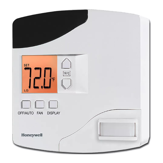
Figure 1 E528.4G
to the left of the junction box. A low-voltage mounting plate, mud
ring, or low-voltage caddy may be used for mounting 24 volt
applications.
1.
Figure 2 E528.4G
2.
3.
4.
5.
Wiring
Copyright © 2013 INNCOM
Unheated (un-cooled) areas behind the thermostat
If RF equipped, do not install near other RF
sources/transmitters
Remove the two small screws at the base of the e528.
Pull the bottom of the back-mounting plate slightly away
from the front housing, then pull the back-mounting plate
down.
Position the back plate insulator within the mounting plate
as shown in Figure 3 below.
Feed wires through the insulator to minimize airflow.
Attach the mounting plate to the junction box using the
mounting screws provided. Ensure that the plate is
mounted with the raised arrow pointing UP.
Figure 3 E528 Back Assembly
H5 RS485 network
header
H4 Power input
H6 ES1 key
H7 System 5
H8 PIR sensor
header
Figure 4 E528 Headers
H9 IR5
header
H1 Microprocessor
programming
H3 Temperature sensor/external
temperature control sensor
H2 Humidity
sensor
Advertisement

Related Manuals for Honeywell INNCOM e528 Series


Summary of Contents for Honeywell INNCOM e528 Series
- Page 1 2G and 3G components, the e528.4G is now the standard sensor INNCOM install, but 2G and 3G installations are still supported. H6 ES1 key H7 System 5 H8 PIR sensor header Figure 4 E528 Headers Copyright 2013 INNCOM by Honeywell...
- Page 2 The e528.4G can be used to retrofit an 250 to H5 of the e528. application where a legacy e528 was used. Follow the procedure below: 4G to 2G Standalone application: with/without door switch input (no backhaul network) Copyright 2013 INNCOM by Honeywell...
- Page 3 (2) this device must accept any • Press and hold °F/°C interference received, including interference that may cause • • Press and release OFF/AUTO undesired operation. • Press and release DISPLAY Release °F/°C • Go to (Room ID) • Copyright 2013 INNCOM by Honeywell...
- Page 4 PN 292-100 The followings statements are required in the final product user manuals: This equipment has been tested and found to comply with the limits for a Class A digital device, pursuant to Part 15 of the FCC Rules. These limits are designed to provide reasonable protection against harmful interference when the equipment is operated in a commercial environment.