Table of Contents
Advertisement
Quick Links
NMF91 Series User Manual
No. G03-NMF91-F
Rev: 4.0
Release date: October 1, 2019
Trademark:
* Specifications and Information contained in this documentation are furnished for information use only, and are
subject to change at any time without notice, and should not be construed as a commitment by manufacturer.
Advertisement
Table of Contents

Related Manuals for JETWAY NMF91 Series


Summary of Contents for JETWAY NMF91 Series
- Page 1 NMF91 Series User Manual No. G03-NMF91-F Rev: 4.0 Release date: October 1, 2019 Trademark: * Specifications and Information contained in this documentation are furnished for information use only, and are subject to change at any time without notice, and should not be construed as a commitment by manufacturer.
-
Page 2: Table Of Contents
TABLE OF CONTENT ENVIRONMENTAL SAFETY INSTRUCTION ................iii ENVIRONMENTAL PROTECTION ANNOUCEMENT ..............iii USER’S NOTICE ........................iv MANUAL REVISION INFORMATION ..................iv ITEM CHECKLIST ........................iv CHAPTER 1 INTRODUCTION OF THE MOTHERBOARD SPECIFICATION ......................1 LAYOUT DIAGRAM ....................2 CHAPTER 2 HARDWARE INSTALLATION JUMPER SETTING .....................5 CONNECTORS AND HEADERS ................9 2-2-1 REAR I/O BACK PANEL CONNECTORS ............9 2-2-2... -
Page 3: Environmental Safety Instruction
Environmental Safety Instruction Avoid the dusty, humidity and temperature extremes. Do not place the product in any area where it may become wet. 0 to 40 centigrade is the suitable temperature. (The figure comes from the request of the main chipset) ... -
Page 4: User's Notice
USER’S NOTICE COPYRIGHT OF THIS MANUAL BELONGS TO THE MANUFACTURER. NO PART OF THIS MANUAL, INCLUDING THE PRODUCTS AND SOFTWARE DESCRIBED IN IT MAY BE REPRODUCED, TRANSMITTED OR TRANSLATED INTO ANY LANGUAGE IN ANY FORM OR BY ANY MEANS WITHOUT WRITTEN PERMISSION OF THE MANUFACTURER. -
Page 5: Specification
Chapter 1 Introduction of the Motherboard 1-1 Specification Spec Description Design PCB Size: 24.5 x 24.5 cm Chipset Intel G41 Memory Controller Hub (MCH) Chipset Intel ICH7 / ICH7R (optional) Chipset CPU Socket Intel ® Socket 775 Core™2 Quad/Core™2 Extreme/Core™2 Duo/ ... -
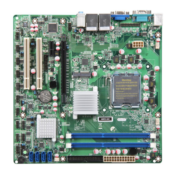
Page 6: Layout Diagram
1-2 Layout Diagram Rear IO Diagram RJ-45 LAN Ports PS/2 Mouse Port Line-IN Serial Port VGA Port Line-OUT MIC-IN PS/2 Keyboard Port USB Ports Motherboard Internal Diagram PS2 KB/Mouse Ports SYS FAN2 Header CPU FAN Header CPU Socket mPGA775 DDRIII DIMMx2 Serial Port ATX Power Connector... - Page 7 Motherboard Jumper Position JP13 JBAT JP15 COPEN JP10 JP16 JP14 Jumper Jumper Name Description JBAT CMOS RAM Clear Function Setting 3-pin Block K/B,UL1 Power on Function Setting 3-pin Block UL2 Power on Function Setting 3-pin Block USB 3/4 Power On Function Setting 3-pin Block Mini PCI-E Power VCC3.3V/3.3V SB 3-pin Block...
- Page 8 Connectors Connector Name Description PS2 Keyboard& Mouse Connectors 6-pin Female COM1 Serial Port COM Connector 9-pin Connector VGA1 Video Graphic Attach Connector 15-pin Female USB from UL1/UL2 USB Port Connectors 4-pin Connectors LAN from UL1/UL2 RJ-45 LAN Connectors 8-pin Connectors Audio Connector 3-phone Jack ATXPWR...
-
Page 9: Chapter 2 Hardware Installation
Chapter 2 Hardware Installation 2-1 Jumper Setting (1) Clear CMOS (3-pin): JBAT JBAT JBAT 1-2 Closed: Normal 2-3 Closed: Clear CMOS CMOS RAM Clear Setting (2) JP1 (3-pin):K/B, UL1 Power On Function Setting 1-2 closed : K/B, UL1 Header POWER-ON Disabled(default) 2-3 closed: K/B, UL1 Header POWER-ON Enabled (3) JP4 (3-pin):UL2 Power on Function Setting 1-2 Closed: UL2 POWER-ON Disabled (default) - Page 10 (4) JP5 (3-pin): USB 3/4 Power On Function Setting 1-2 closed : USB 3/4 Header POWER-ON Disabled(default) 2-3 closed: USB 3/4 Header POWER-ON Enabled (5) JP6 (3-pin): Mini PCI-E Power VCC 3.3V/ 3.3 VSB Function Select 2-3 closed : MINI PCI-E 1-2 closed :...
- Page 11 (7)JP9 (6-pin): COM2 Pin9 function select 1-2 closed: RS232 3-4 closed : +12V 5-6 closed : +5V (8) JP10 (6-pin): COM2 Port RS232/485/422 Function Select JP10 3-4 closed : RS485 1-2 closed: RS232 5-6 closed : RS422 (9)JP13 (6-pin): COM7 Pin9 function select JP13 1-2 closed: RS232 3-4 closed : +12V...
- Page 12 (10)JP14 (6-pin): COM8 Pin9 function select JP14 1-2 closed: RS232 3-4 closed : +12V 5-6 closed : +5V (11)JP15 (6-pin): COM9 Pin9 function select JP15 1-2 closed: RS232 3-4 closed : +12V 5-6 closed : +5V (13)JP16 (6-pin): COM10 Pin9 function select JP16 1-2 closed: RS232 3-4 closed : +12V...
-
Page 13: Connectors And Headers
(13)COPEN (2-pin): Case Open Message Display function select COPEN 1-2 Open: Normal 1-2 Short: Case Open Case Open Display Function Pin 1-2 shorted: Case open display function enabled. In this case if you case is removed, next time when you restart your computer a message will be displayed onscreen to inform you of this. -
Page 14: Motherboard Internal Connectors
Line-in: (BLUE) Audio input to sound chip Line-out: (GREEN) Audio output to speaker MIC: (PINK) Microphone Connector 2-2-2 Motherboard Internal Connectors Power Connector (24-pin block): ATXPWR ATX Power Supply connector: This is a new defined 24-pins connector that usually comes with ATX case. The ATX Power Supply allows using soft power on momentary switch that connect from the front panel switch to 2-pins Power On jumper pole on the motherboard. - Page 15 Figure1:20-pin power plug Figure 2:24-pin power plug (2) ATX 12V Power Connector (8-pin block) : ATX12V1 This is a new defined 8-pin connector that usually comes with ATX Power Supply. The ATX Power Supply which fully supports AMD AM3 processor must including this connector for support extra 12V voltage to maintain system power consumption.
-
Page 16: Pin Header Definition
second drive to Slave mode by setting its jumpers accordingly. Please refer to the documentation of your hard disk for the jumper settings. Two hard disks can be connected to each connector. The first HDD is referred to as the “Master” and the second HDD is referred to as the “Slave”. ... - Page 17 (3) Speaker connector: SPEAK This 4-pin header connects to the case-mounted speaker. See the figure below. (4) Power LED: PWR LED The Power LED header is light on while the system power is on. Connect the Power LED header from the system case to this pin. Pin 1 Pin 1 PWRLED Header...
- Page 18 (6) USB Port Headers (4-pin): USB4 Pin 1 USB4 Header (8) FAN Power Headers: SYSFAN1(3-pin), SYSFAN2(4-pin),CPUFAN (4-pin) CPUFAN SYSFAN2 Fan Clock SYS FAN1 +12V Fan Power FAN Headers (9) GPIO Header (10-pin): GPIO_CON GPIO 1 Pin 1 GPIO1 Header (10) Serial Port Header (9-Pin): COM2/3/4/5/6/7/8/9/10 Pin6 Pin5...
- Page 19 (11) RS232/422/485 Header (4-pin): TX-RXCOM1 Pin 1 TX-RXCOM1 Header (12) RS232/422/485 Header (5-pin): IR Pin 1 IR infrared module Header (13) HDMI-SPDIF Out header (2-pin): HDMI_SPDIF Pin1 HDMI_SPDIF_OUT HDMI_SPDIF Header (14) TPM header (19-pin): TPM Pin 1 TPM Header...
- Page 20 (15) Dual Channel Memory Installation config Slot 1 Slot 2 install install install install Notice! For dual channel installation, you need to install the same brand, speed, size and type memory module. It is unable to activate dual channel feature if you install only one memory module. Slot order can be from left-to-right or right-to-left, and it must be installed in pairs.
-
Page 21: Chapter 3 Introducing Bios
Chapter 3 Introducing BIOS Notice! The BIOS options in this manual are for reference only. Different configurations may lead to difference in BIOS screen and BIOS screens in manuals are usually the first BIOS version when the board is released and may be different from your purchased motherboard. Users are welcome to download the latest BIOS version form our official website. -
Page 22: Getting Help
Getting Help Main Menu The on-line description of the highlighted setup function is displayed at the bottom of the screen. Status Page Setup Menu/Option Page Setup Menu Press F1 to pop up a small help window that describes the appropriate keys to use and the possible selections for the highlighted item. -
Page 23: Standard Bios Features
Use this menu to specify your settings for PnP and PCI configurations. PC Health Status This entry shows your PC health status. Miscellaneous Control Use this menu to specify your settings for Miscellaneous Control. Load Optimized Defaults Use this menu to load the BIOS default values these are setting for optimal performances system operations for performance use. -
Page 24: Advanced Bios Features
Date The date from 1 to 31 can be keyed by numeric function keys. Year The year depends on the year of the BIOS. System Time The time format is <hour><minute><second>. SATA Channel 1/2/3/4 Master Primary IDE Master/Slave While entering setup, BIOS auto detects the presence of harddisk devices. This displays the status of auto detection of harddisk devices. -
Page 25: Cpu Feature
This item allows BIOS to skip certain tests while booting. This will decrease the time needed to boot the system. The optional settings: Disabled; Enabled. Boot Up NumLock Status The default value is On. On (default) Keypad is numeric keys. Keypad is arrow keys. -
Page 26: Integrated Pheriphrals
DRAM Timing Settings by SPD The optional settings are: Disabled; Enabled. Memory Hole The optional settings are: Disabled; 15MB-16MB. Initate Graphic Adapter Use this item to select which graphic controller to use as the primary boot device. IGD Mode Select Use this item to select the amount of system memory used by the internal graphics device. -
Page 27: Onboard Sata Function
3-7-1 Onboard SATA Function ATA/IDE Configuration The optional settings are: Disabled; Compatible; Enhanced. Configure SATA Channels The optional settings are: Before PATA; Behind PATA. IDE Detect Time Out(Sec) Use this item to select the time out value for detecting ATA/ATAPI device(s). 3-7-2 Onboard Device Function Onboard PCIE LAN/ PCIE LAN 2 Controller The optional settings are: Enabled;... -
Page 28: Onboard Super Io Function
The optional settings are: Enabled; Disabled. High Definition Audio This item allows you to decide to auto /disable the chipset family to support HD Audio. The settings are: Auto, Disabled. USB Host Controller The optional settings are: Enabled; Disabled. USB 2.0 Function The optional settings are: Enabled;... -
Page 29: Power Management Setup
Serial Port 1/2/3/4/5/6/7/8/9/10 Address This item allows BIOS to select base addresses for serial ports. Serial Port 3/4/5/6/7/8/9/10 IRQ This item allows BIOS to select serial port IRQ. Serial Port 2 Mode The optional settings are : Normal; IrDA(1.6us); IrDA(3/16 bit). Serial Port 2 RS485 Select The optional settings are :... -
Page 30: Pnp/Pci Configurations
Case Open Detect The optional settings: Disabled; Enabled. ACPI Suspend Type Users can select the ACPI state used for system suspend. The optional settings are: S1(POS); S3(STR). Video Off In Suspend Use this item to power down video in Suspend or Standby mode. Suspend Mode Use this item to select the specified time for system to go into suspend. -
Page 31: Pc Health Status
Reserved: Specified IRQ is reserved for use by legacy ISA devices. PCI/VGA Palette Snoop The optional settings are: Enabled; Disabled. Enabled: to inform the PCI devices that an ISA graphics device is installed in the system so the card will function correctly. 3-10 PC Health Status This section shows the Status of you CPU, Fan, and Warning for overall system status. -
Page 32: Smart Fan Configuration
3-10-1 Smart Fan Configuration Press [Enter]to set certain values for the following three items: CPUFAN Smart Mode , SYSFAN1 Smart Mode and SYSFAN2 Smart Mode to set respectively for value in Full-Speed Temp.; Idle Temp. and Idle-Speed Duty . 3-11 Miscellaneous Control CPU Clock Ratio Use this item to set the ratio between CPU core clock and FSB frequency. -
Page 33: Password Setting
CPU Output Clock Swing Select a value for CPU output clock swing in the setting range of 700mV to 1400mV. DRAM Clock at Next Boot This item allows you to set DRAM clock. Host/PCI Clock at Next Boot The optional settings are from 200 to 600. CPU Vcore 7-Shift Use this item to set value in CPU Vcore 7-Shift function. -
Page 34: Load Optimized /Standarddefaults
You determine when the password is required within the BIOS Features Setup Menu and its Security option. If the Security option is set to “System”, the password will be required both at boot and at entry to Setup. If set to “Setup”, prompting only occurs when trying to enter Setup.