Table of Contents
Advertisement
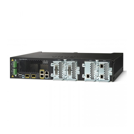
Installing and Connecting the Router
This section describes how to install and connect Cisco CGR 2010 routers to a LAN or WAN, as well as how to connect
AC or DC power to the router.
These topics are discussed.
What you Need to Know, page 26
Before You Begin, page 27
Unpacking the Router, page 27
Installing the Router in a Rack, page 27
Power-Supply Modules, page 30
Connecting to a Console Terminal or Modem, page 38
Installing the Cisco Microsoft Windows USB Device Driver, page 41
Uninstalling the Cisco Microsoft Windows USB Driver, page 42
Connecting to the Auxiliary Port, page 43
Connecting WAN and LAN Interfaces, page 44
Auxiliary Port, Console Port, and Adapter Pinouts for the Cisco CGR 2010 Router, page 45
Connectors and Cabling for the 8-Port Asynchronous/ Synchronous RS-232 GRWIC, page 51
Note:
To see translations of the warnings that appear in this publication, see
Regulatory Compliance and Safety
Caution:
For the optimum temperature ranges, do not operate it in an area that less than the minimum of 40°C and
exceeds a maximum recommended ambient temperature of 60°C.
Note:
To view specifications for the CGR 2010 router, see the Cisco 2010 Connected Grid Router data sheet at:
http://www.cisco.com/en/US/prod/collateral/routers/ps10967/ps10977/data_sheet_c78_593509.html
Warning:
Only trained and qualified personnel should be allowed to install, replace, or service this equipment.
Statement 1030
Warning:
This unit might have more than one power supply connection. All connections must be removed to
de-energize the unit. Statement 1028
Warning:
Hazardous network voltages are present in WAN ports regardless of whether power to the unit is OFF or
ON. To avoid electric shock, use caution when working near WAN ports. When detaching cables, detach the end
away from the unit first. Statement 1026
Warning:
Do not use this product near water; for example, near a bath tub, wash bowl, kitchen sink or laundry tub,
in a wet basement, or near a swimming pool. Statement 1035
Information.
Cisco Systems, Inc.
www.cisco.com
25
Cisco Connected Grid Routers Series
Advertisement
Table of Contents

Related Manuals for Cisco CGR 2010


Summary of Contents for Cisco CGR 2010
-
Page 1: Installing And Connecting The Router
Installing and Connecting the Router This section describes how to install and connect Cisco CGR 2010 routers to a LAN or WAN, as well as how to connect AC or DC power to the router. These topics are discussed. ... -
Page 2: What You Need To Know
A Microsoft Windows USB driver must be installed before you establish physical connectivity between the router and the PC. Slot and Port Numbers Cisco CGR 2010 routers have built-in ports and new slots. The new slots accommodate new grid router WAN interface cards (GRWICs). See Slot, Port, and Interface Information, page 11... -
Page 3: Before You Begin
Installing and Connecting the Router Before You Begin Before You Begin Before installing and connecting a Cisco CGR 2010 router, read the safety warnings and gather the following tools and equipment: ESD-preventive cord and wrist strap Number 2 Phillips screwdriver ... -
Page 4: Rack-Mounting The Chassis
Rack-Mount Brackets for the Cisco CGR 2010 Router Attaching Rack-Mount Brackets to Cisco CGR 2010 Routers To attach the long side of each bracket to the Cisco CGR 2010 router, use four of the supplied number-8 Phillips flat-head screws. Figure 2 on page 28 shows how to attach the brackets to the sides of the router with the power-supply side forward. -
Page 5: Mounting The Router In A Rack
Caution: A space of 1 RU above each Cisco CGR 2010 router is required for sufficient air ventilation. Figure 4 on page 30... -
Page 6: Power Supply Modules
Power-Supply Modules This section describes how to connect AC power and DC power to the Cisco CGR 2010 router. This section also describes how to protect the Cisco CGR 2010 router terminal block from exposure with the terminal block cover and shut off power. -
Page 7: Connecting Ac Power
Power supply Power supply captive screws Connecting AC Power This section explains how to connect AC power to the Cisco CGR 2010 router. Warning: Read the installation instructions before connecting the system to the power source. Statement 1004 To connect an AC power supply: Verify that power is off to the circuit on the power supply that you are removing. - Page 8 Installing and Connecting the Router Power-Supply Modules Figure 6 Power-Input Terminal Designations Line connection for AC power Positive connection for high-voltage DC Neutral connection for AC power Negative connection for low-voltage DC Negative connection for high-voltage DC Positive connection for low-voltage DC Ground connection Note that the line connection for AC power and the negative connection for high-voltage DC power share the same power input terminal—that is, this terminal can be used for either AC or DC power.
- Page 9 Do not touch the terminal block when energy is restored. The terminal block screw heads and any exposed wiring could have hazardous line voltages (depending on the voltage source). The Cisco CGR 2010 router is intended to be installed in a restricted access location and serviced by trained personnel only.
-
Page 10: Connecting Dc Power
If you have two power supplies, install the second power supply in the available slot and repeat Step 1 through Step Connecting DC Power This section explains how to connect DC power to the Cisco CGR 2010 router. Warning: Read the installation instructions before connecting the system to the power source. Statement 1004 To connect an DC power supply: Verify that power is off to the circuit on the power supply that you are removing. - Page 11 If you need a cable to connect to the low-voltage DC power supply, cut off the plug from the power cord and hard-wire the Cisco CGR 2010 low-voltage DC input directly to its power source, observing the correct polarity markings.
- Page 12 If you have two power supplies, install the second power supply in the available slot and repeat Step 1 through Step Protecting the Terminal Block from Exposure You can protect the Cisco CGR 2010 router terminal block from exposure with the terminal block cover. See Figure 12...
-
Page 13: Shutting Off Power
Even though shutting off power to the Cisco CGR 2010 router is anticipated to be infrequent, there may be occasion to turn off the router. There is no on/off switch on the Cisco CGR 2010 router. This ensures that there will not be any accidental shutdown due to inadvertently turning off a power switch;... -
Page 14: Replacing Power Supplies And Redundant Power Supplies
The router has asynchronous serial ports and auxiliary ports. These ports provide administrative access to the router either locally (with a console terminal or a PC) or remotely (with a modem). To configure the router through the Cisco IOS command-line interface (CLI), you must establish a connection between the router console port and either a terminal or... -
Page 15: Connecting To The Serial Port With Microsoft Windows
USB serial port for the first time on a Windows-based PC, install the USB driver now according to the instructions in the following sections. Installing the Cisco Microsoft Windows XP USB Driver, page 41 Installing the Cisco Microsoft Windows 2000 USB Driver, page 42... -
Page 16: Connecting To The Console Port With Mac Os
Installing and Connecting the Router Connecting to a Console Terminal or Modem Figure 14 Connecting the USB Console Cable to the Cisco CGR 2010 Router Cis co CG R 20 10 SL OT 3 SL OT 2 SL OT 1... -
Page 17: Connecting To The Console Port With Linux
A USB device driver must be installed the first time a Microsoft Windows-based PC is connected to the USB serial port on the router. These topics are discussed: Installing the Cisco Microsoft Windows XP USB Driver, page 41 Installing the Cisco Microsoft Windows 2000 USB Driver, page 42 ... -
Page 18: Installing The Cisco Microsoft Windows 2000 Usb Driver
The USB console is ready for use. Uninstalling the Cisco Microsoft Windows USB Driver This section provides instructions for how to uninstall the Cisco Microsoft Windows USB device driver. Uninstalling the Cisco Microsoft Windows XP and 2000 USB Driver, page 43... -
Page 19: Uninstalling The Cisco Microsoft Windows Xp And 2000 Usb Driver
Connecting to the Auxiliary Port Uninstalling the Cisco Microsoft Windows Vista USB Driver, page 43 Uninstalling the Cisco Microsoft Windows XP and 2000 USB Driver You can remove Microsoft Windows XP and the 2000 USB driver using the Windows Add or Remove Programs utility or the setup.exe program. -
Page 20: Connecting Wan And Lan Interfaces
This section describes how to connect WAN and LAN interface cables. Note: One or two Ethernet cables are typically provided with the router. Additional cables and transceivers can be ordered from Cisco. For ordering information, contact customer service. For cable pinouts, see Cisco Modular Access Router Cable Specifications. -
Page 21: Connection Procedures And Precautions
Cisco Modular Access Router Cable Specifications for information about choosing these cables. Auxiliary Port, Console Port, and Adapter Pinouts for the Cisco CGR 2010 Router This section explains the different ports and adapter pinouts available for the Cisco CGR 2010 router. -
Page 22: Auxiliary And Console Ports
Auxiliary and Console Ports The console and auxiliary ports on Cisco IOS® routers are asynchronous serial ports. The console port and the auxiliary port are configured as data terminal equipment (DTE). For Cisco 2000 Series Routers, the console and auxiliary ports both use RJ-45 connectors. - Page 23 Installing and Connecting the Router Auxiliary Port, Console Port, and Adapter Pinouts for the Cisco CGR 2010 Router Figure 16 Identifying a Rollover Cable Pin 1 on one connector and pin 8 on the other connector should be the same color.
- Page 24 Installing and Connecting the Router Auxiliary Port, Console Port, and Adapter Pinouts for the Cisco CGR 2010 Router Figure 17 RJ-45 Cable to DB-9 Female Adapter RJ-45-to-DB-9 female adapter RJ-45 cable Figure 18 RJ-45 to RJ-45 Rollover Cable RJ-45-to-RJ45 Router...
- Page 25 Installing and Connecting the Router Auxiliary Port, Console Port, and Adapter Pinouts for the Cisco CGR 2010 Router Figure 20 RJ-45 to DB-25 Female Adapter RJ-45-to-DB-25 female adapter RJ-45 cable Table 8 on page 49 shows the pinout descriptions for the DB-25 connections:...
- Page 26 Installing and Connecting the Router Auxiliary Port, Console Port, and Adapter Pinouts for the Cisco CGR 2010 Router Figure 21 RJ-45 to DB-25 Adapter (Terminal) RJ-45-to-RJ45 Router Modem roll-over cable RJ-45-to-DB-25 adapter (labeled Modem) Figure 22 RJ-45 to DB-25 Male Adapter...
-
Page 27: Connectors And Cabling For The 8-Port Asynchronous/ Synchronous Rs-232 Grwic
The 8-port serial RS-232 GRWIC enables applications such as legacy protocol transport, console server, and dial access server. Combining a high-density serial GRWIC with the Cisco CGR 2010 router enables utilities to transport Supervisory Control and Data Acquisition (SCADA) over an IP network. - Page 28 Synchronous mode or Bit-Synchronous mode. Table 12 on page 53 shows the pinouts for the CAB-HD4-232FC and CAB-HD4-232MT serial cables. Note: In the Direction column, Input means data input to the CGR 2010 router; Output means output from the CGR 2010 router.
- Page 29 Installing and Connecting the Router Connectors and Cabling for the 8-Port Asynchronous/ Synchronous RS-232 GRWIC Table 12 Pinouts for Male and Female DB-25 Cables Signal Direction Description SHIELD — Shield Ground Input Transmit Data. Arriving data from DCE. Output Transmit Data. Sending data from DTE. Input Request to Send Output...
- Page 30 Installing and Connecting the Router Connectors and Cabling for the 8-Port Asynchronous/ Synchronous RS-232 GRWIC Table 13 Pinouts for CAB-9AS-M (Male DB-9) (continued) Signal Direction Description Output Request to Send. Raised by DCE when it wishes to send. Expects CTS from DTE. Input Clear to Send.