
Related Manuals for Panasonic PAW-500ZDX3N


Summary of Contents for Panasonic PAW-500ZDX3N
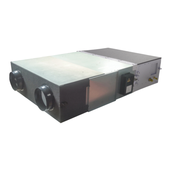
- Page 1 ERV+DX MANUALE DI INSTALLAZIONE USO E MANUTENZIONE INSTALLATION, USE AND MAINTENANCE MANUAL UNITÀ DI RECUPERO CALORE CON BATTERIA A ESPANSIONE DIRETTA ENERGY RECOVERY VENTILATION UNIT WITH DX COIL...
- Page 2 INDEX DEClARATION Of CONfORMITY page 20 GENERAl WARNINGS page 21 SYMBOlS USED page 22 IDENTIfICATION Of ThE UNIT page 22 SECTION 1 - GENERAl ChARACTERISTICS Presentation of the manual page 23 General characteristics page 23 ERV+DX series technical data page 23 Dimensions and weights page 24 SECTION 2 - TRANSPORT...
-
Page 3: Declaration Of Conformity
DECLARATION OF CONFORMITY SIC s.r.l. Società Unipersonale Company Viale dell’Industria, 25 37044 Address Province Cologna Veneta Italy City State DECLARES UNDER ITS OWN RESPONSIBILITY THAT THE MACHINERY Heat Recovery Unit ERV+DX Description Series ERV+DX PAW – 500 ZDX3N; ERV+DX PAW – 800 ZDX3N; ERV+DX PAW – 01 KZDX3N Models Double flow mechanical ventilation with static, cross flow enthalpic heat exchanger and direct expansion coil Function... -
Page 4: General Warnings
GENERAl WARNINGS This manual is an integral part of the apparatus and then it must be preserved with care and it ALWAYS must accompany the machine, even in the case of cession to another owner or user or in the case of a transfer on another system. In the case of its damage or losing, ask another copy to the distributor Company. -
Page 5: Identification Of The Unit
SYMBOlS USED WARNING DANGER DANGER Of ElECTRICAl ShOCK QUAlIfIED STAff ONlY PROhIBITION IDENTIfICATION Of ThE UNIT Manufacturer's mark Manufacturer's address Model Serial number Voltage; number of phases; frequency Maximum absorbed current [A] Code Manufacturing date CE mark Barcode IMpORTANT NOTES THE HEAT RECOvERy UNITS OF ERv+DX SERIES ARE ONLy SUITABLE FOR INTERNAL INSTALLATION The heat recovery unit is a machine designed and built exclusively to change air in the civil environments, incompatible with toxic and inflammable gases. -
Page 6: Section 1 - General Characteristics
• Built-in electric box equipped with PCB to control internal fan speed and to interconnect outdoor/indoor units • Duct connection by circular plastic collars 1.3 ERV+DX series technical data MODEllO / MODEL ERV+DX PAW-500zDX3N PAW-800zDX3N PAW-1000zDX3N m 3 /h Portata aria nominale / 1000... - Page 7 (1) Multiple = Multispeed > 3 Man = Manual by selector switch or control panel; 0-10V = By potentiometer or control panel; VSD = Modulation by air quality or air humidity sensor (2) Sound pressure level calculated at 1 m far from: ducted supply-exhaust air/ducted return-fresh air intake/service side, at nominal conditions.
-
Page 8: Section 2 - Transport
SECTION 2 - TRANSPORT 2.1 Packing • The regenerators and their accessories are inserted in cardboard boxes that will have to remain integral until the moment of the assembly. • The components that, due to technical requirements, are not assembled, are supplied packed in a suitable covering and fixed to the inside or outside of the unit. - Page 9 • Spare parts must correspond to the requirements defined by the Manufacturer Company. • In case of dismantling of the unit, follow the relevant antipollution norms. N.B. When using the unit, the installer and the user must take into account and place remedy to all the other types of risk connected with the sistem.
- Page 10 3.5 Positioning of the machine In the continuation are illustrated some sequences of the assembly: 1. Carry out the drilling on the ceiling and fix six M8 threaded rods as shown in the figure. 2. Position the unit on the six threaded rods (eight brac- kets available).
- Page 11 3.8 Connecting the Refrigerant Tubing The unit is supplied with plugged direct expansion coil: to ensure its tightness during storage and transport, inside it is loaded nitrogen gas at a higher pressure than atmospheric. CAUTION: Nitrogen is sealed inside the main unit. Before loosening the flare section, perform the fol- lowing airtightness check.
-
Page 12: Insulating The Refrigerant Tubing
3.8 Connecting the Refrigerant Tubing CAUTIONS DURING BRAzING Replace air inside the tube with nitrogen gas to prevent copper oxide film from forming during the brazing process. (Oxygen, carbon dioxide and Freon are not acceptable.) ● Do not allow the tubing to get too hot during brazing.The nitrogen gas inside the tubing may overheat, causing refrigerant system valves to become damaged. -
Page 13: Section 4 - Electrical Connections
SECTION 4 - ElECTRICAl CONNECTIONS Before beginning whichever operation make sure that the voltage supply is cut off. • The electrical connections to the control cabinets must be carried out by specialized staff, following the supplied wiring diagrams. • Make sure that the voltage and the frequency specified on the nameplate correspond to those of the power supply line. Carry out the connection with cables of a section which is adapted to the engaged power and in the respect of the local norms. -
Page 14: Section 5 - Start Up Controls
4.2 Wiring diagram LINEA ALIMENTAZIONE: PREDISPORRE A MONTE UNA ADEGUATA PROTEZIONE CON INTERRUTTORE MAGNETOTERMICO DIFFERENZIALE / POWER LINE: PROVIDE A PROPER SAFETY DEVICES EQUIPPED WITH DIFFERENTIAL MAGNETOTHERMAL SWITCH SECTION 5 - START UP CONTROlS Before starting the unit check the following: •... -
Page 15: Section 6 - Ordinary Maintenance
SECTION 6 - ORDINARY MAINTENANCE 6.1 Warning BEfORE UNDERTAKING WhIChEVER MAINTENANCE OPERATION MAKE SURE ThAT ThE MAChINE IS SWITCh Off AND ThAT IT CAN NOT BE ACCIDENTAllY CONNECTED TO ThE POWER. IT IS ThEREfORE NECESSARY TO CUT Off ThE ElECTRIC SUPPlY DURING All MAINTENANCE OPERATIONS. - Page 16 6.3 Yearly checks • Verification of the whole electrical installation and in particular the tightening of the cable connections. • Verification of the tightening of all bolts, nuts, flanges and water connections that could be loose because of vibrations. 6.3.1 Bioxigen purifying system check Once a year at least or when a drop in purifying efficiency is felt cleaning of capacitor shall be done.
-
Page 17: Section 7 - Breakdown Diagnostic
SECTION 7 - BREAKDOWN DIAGNOSTIC SYMPTOMS POSSIBlE CAUSE No power supply. The switches of the thermostat are not in the right position of working. fans not running There are foreign bodies that block the rotors. Electrical connections are released. Too low airflow. Poor cooling / heating Insufficient refrigerant fill (check refrigerant circuit). -
Page 18: Section 9 - Spare Parts
SECTION 9 - SPARE PARTS KEy and SpARE pART LIST & CODES Model AIR - FILTER FAN pCB COLLAR FAN MOTOR FAN IMpELLER HEAT RECOvERy MAIN pCB G3 Filter pM 2.5 filter PAW-500 zDX3N CF0P30MICH050050 CF0M90MICH050480 MV00BOC0MICH0500 MTE00000MICH0500 VT000GIRMICH0500 PR000E000MICH050 CT00000MICEH0250 QE1CV62331675890 PAW-800 zDX3N... - Page 19 PRODOTTO E PROGETTATO PER MANUFACTURED AND DESIGNED FOR da / by Viale dell’Industria, 25 37044 Cologna Veneta (Verona) Italy tel. +39 0442 412741 - fax +39 0442 418400 E-mail: info@sicsistemi.com - www.sicsistemi.com...