Table of Contents
Advertisement
Quick Links
Download this manual
See also:
User Manual
Advertisement
Table of Contents

Related Manuals for Zennio Flat 55


Summary of Contents for Zennio Flat 55
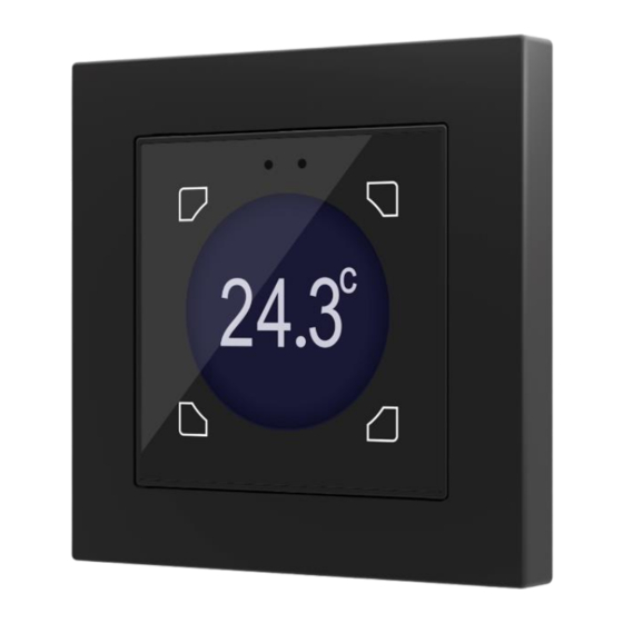
- Page 1 Flat 55 Display 55x55mm Capacitive Glass Touch Panel with Round Display55x55mm with round display ZVI-F55D Application Programme Version: [2.0] User Manual Version: [2.0]_a www.zennio.com...
-
Page 2: Table Of Contents
Flat 55 Display CONTENTS Contents ........................... 2 Document Updates ........................3 Introduction ........................4 Flat 55 Display ......................4 Installation ......................... 6 Start-Up and Power Loss .................... 7 Configuration ........................8 General ........................8 2.1.1 Configuration ......................8 2.1.2 Advanced Configuration ..................16 Buttons ........................ -
Page 3: Document Updates
Flat 55 Display DOCUMENT UPDATES Version Changes Page(s) Changes in the application program: 63-66, 77-79 New page style: Thermostat. Parameter to include plus sign before positive setpoints. [2.0]_a Temperature Probe: new option to select the temperature probe included with the device (ref. -
Page 4: Introduction
LED backlight to confirm the press of the buttons or showing states. Flat 55 Display is a fully customisable solution for the room control where the user needs to control climate systems, lighting, blinds, scenes, etc. - Page 5 Flat 55 Display Possibility of locking / unlocking the touch panel through binary orders or scenes, and of setting a timed/automatic locking of the device (cleaning function). Welcome greeting on the display and Welcome Back object (binary or scene). Screensaver function.
-
Page 6: Installation
9. Luminosity and Proximity Sensor. Figure 1. Schematic diagram. Flat 55 Display is connected to the KNX bus through the built-in terminal (4). An external DC power supply is not needed. A short press on the Prog./Test button (7) will make the device enter the programming mode. -
Page 7: Start-Up And Power Loss
Flat 55 Display START-UP AND POWER LOSS After download or device reset it is necessary to wait for 2 minute without performing any action in order to make it possible a proper calibration of: Proximity sensor. Luminosity sensor. Button presses. -
Page 8: Configuration
Flat 55 Display 2 CONFIGURATION After importing the corresponding database in ETS and adding the device into the topology of the project, the configuration process begins by entering the Parameters tab of the device. GENERAL In order to allow the device to perform the desired functions, a number of options must be parameterized, either related to its general behavior (screensaver, sounds, lock procedure of the touch panel…) or to advanced features (cleaning function, welcome... - Page 9 Flat 55 Display This tab shows the following parameters: : read-only parameter to make it evident that the “Buttons” Buttons [enabled] tab is always enabled in the tab tree on the left. See section 2.2 for details. Display [enabled]: read-only parameter to make it evident that the “Display”...
- Page 10 “waking up” the device display when detecting presence. Note: Please refer to the specific manual “Luminosity and Proximity Sensor” (available in the Flat 55 Display product section at the Zennio homepage, www.zennio.com) for detailed information about the functionality and the configuration of the related parameters.
- Page 11 [General] Display - Brightness: 1-byte percentage object for changing the display brightness level. 2.1.1.1 BACKLIGHT Flat 55 Display allows managing the brightness of the display and the LEDs according to two operating modes: normal mode and night mode. Note: Contrast is not a configurable feature in this device.
- Page 12 Flat 55 Display 2.1.1.2 SCREENSAVER The screensaver is a special page that will only be shown after a period of inactivity, configurable by parameter. It is possible to choose whether the time is to be displayed, by means of an analogue clock or by means of a digital clock, the current temperature or, only if a digital clock is chosen, both (which will be displayed alternately every 5 seconds).
- Page 13 2.1.1.3 TOUCH LOCKING The touch panel of Flat 55 Display can be optionally locked and unlocked anytime by writing a configurable one-bit value to a specific object provided for this purpose. It can also be done through scene values.
- Page 14 2.1.1.5 SOUNS Flat 55 Display emits 3 types of sounds, depending on the action performed: Press Confirmation: short beep indicating that the user has pressed a button. This only applies to step controls, i.e., controls that walk through a certain range of values and that do not send a value after every touch, but only the final value after the last press.
- Page 15 Flat 55 Display Note: the range of sounds emitted when these actions are performing will be different depending on the sound selected type. Enabling and disabling the button sounds can be done in parameters or through an object, being also possible to define in parameters whether the button sounds should be initially enabled or not.
-
Page 16: Advanced Configuration
Flat 55 Display Button Sound After ETS Download [enabled/disabled]: sets whether the button beeping function should start up enabled (default option) or disabled after an ETS download. Object Polarity [0 = Disabled, 1 = Enabled / 0 = Enabled, 1 = Disabled]:... - Page 17 Flat 55 Display Welcome Back Object [disabled/enabled]: enables or disables the “Welcome Back Object” tab. See section 2.1.2.3 for details. Warning [disabled/enabled]: enables or disables the “Warning” tab. See section 2.1.2.4 for details. Object to Change the Temperature Scale [disabled/enabled]: enables the 1-bit object “[General] Temperature Scale”), which permits changing in...
- Page 18 Flat 55 Display A cleaning icon can be shown during the cleaning state. When the timeout is about to end, it is also possible to make this cleaning icon blink or to make the device beep (or both). ETS PARAMETERISATION After enabling “Cleaning Function”...
- Page 19 Flat 55 Display 2.1.2.2 WELCOME GREETING This function permits showing the user a welcome message of up to four lines of text on the display, each of which can be object-dependant or set in parameters. When a “1” is received through the welcome greeting one-bit object, the display will become blank and show the welcome text.
- Page 20 LEDs of the buttons should blink or not during the welcome greeting. 2.1.2.3 WELCOME BACK OBJECT Flat 55 Display can send a specific object (a one-bit value, a scene value or both, depending on the parameterisation) to the KNX bus when the user presses a touch button or when the proximity sensor detects presence (if enabled) after a significant amount of time since the last touch or detection.
- Page 21 Flat 55 Display Time to Activate the Welcome Object [1...65535][s] [1…65535][min/h]: sets the minimum time that should elapse after the last button touch (or presence detection, when the proximity sensor is enabled) before the next one triggers the execution of the welcome back function.
- Page 22 Flat 55 Display welcome back function is triggered and the condition (if any) evaluates to true. The desired value should to be set in Scene Number [1…64]. 2.1.2.4 WARNING This function is intended for visual and/or audible notification of an important event.
- Page 23 Flat 55 Display Display Icon [Window Open / Drop-down with icons to be selected]: sets the icon that will be shown on the display once the warning is activated. Enable LED Flashing [enabled/disabled]: sets whether the LEDs of the buttons should blink or not during the warning.
-
Page 24: Buttons
Flat 55 Display BUTTONS 2.2.1 CONFIGURATION Flat 55 Display features four capacitive buttons at the user’s disposal for the execution of actions. Each will perform a specific function any time, as their functions do not depend on alternating menus, pages, etc. - Page 25 Flat 55 Display Two objects (short press / long press). Scene. Scaling constant. Counter constant. Float constant. Dimmer. Shutter. Enumeration. [Climate] Fan. [Climate] Mode. [Climate] Mode Special. Room State.
- Page 26 Flat 55 Display ETS PARAMETERISATION An independent tab for the parameterization of the buttons is shown in ETS by default, initially containing only a sub-tab named “Configuration”. Figure 13. Buttons – Configuration One drop-down list with the following options is shown per button.
-
Page 27: Disable
Flat 55 Display [Disabled] [Regular] [State-Dependent (where available)] [State-Dependent (where available) (both LEDs)] [Dedicated Object] [Configure every button (pair) separately]: in case of selecting the last option, there will be a specific parameter for each control to specifically... - Page 28 Flat 55 Display Switch: whenever the user touches the button, a binary value will be sent to the KNX bus. This value is configurable and may be 0 or 1, or alternate with every touch according to the sequence 1 0 1 …...
- Page 29 Flat 55 Display Counter constant: sends an integer value (configurable) to the bus when the user touches the button. This value can be one-byte or two-byte sized, as well as signed or unsigned. The available ranges are shown next: 1-byte 2-byte 0 –...
- Page 30 Flat 55 Display receive feedback from the dimmer). This object is internally updated after a short or long press but linking it to the real dimmer status is highly advisable. Under a “state-dependent” LED illumination, the LED will remain on/off according to the value of the aforementioned status object (i.e., off when the...
- Page 31 The “State-dependent” LED mode is not available for this function. [Climate] Fan: pressing one of the two buttons will make Flat 55 Display send a binary value to the bus that allows changing the fan speed (up to five levels available).
- Page 32 Under a “state-dependent” LED illumination, the LED will remain on/off according to the current state of the fan. [Climate] Mode: pressing the button will make Flat 55 Display send climate mode values to the bus. Two mode control types are possible: Heat / Cool and Extended (HVAC).
- Page 33 Flat 55 Display Room State: allows controlling the room states (normal, make-up request, do not disturb). User can switch the state between normal and do not disturb or make-up request. Configuring by parameter if will activate do not disturb or make-up request state will be necessary.
- Page 34 Flat 55 Display In case of selecting “Dedicated Object”, the object “[Btn] [In] LED On/Off” will be included in the project topology and a new parameter: Value [0 = Off; 1 = On / 0 = On; 1 = Off] to select the value to switch off and on the LED shows up.
- Page 35 Flat 55 Display Value [0 = Off; 1 = On / 0 = On; 1 = Off]: sets the behaviour of the LED of the button. The options are similar to those of the dedicated-object LED illumination available for other control types.
- Page 36 Flat 55 Display LED Illumination Control [Regular / Dedicated object]. Two Objects (Short Press/Long Press) Figure 19. Individual Button - Two Objects (Short Press / Long Press). Action on Short press [Send 0 / Send 1 / Toggle 0/1 / Send 1-byte Unsigned Int Value]: sets the value to be sent to the bus (through “[Btn]...
- Page 37 Flat 55 Display Scene Figure 20. Individual Button - Scene. Action [Run / Run and Save]: sets whether the value to be sent to the KNX bus when the user touches the button will always be a scene run request or –depending on the length of button press–...
- Page 38 Flat 55 Display In case of selecting Counter Constant, two specific parameters (“Size” and “Signed”) will be displayed to respectively define the size of the constant and whether it is a signed value or an unsigned value. Depending on that, the range and the name of the object will vary.
- Page 39 Flat 55 Display Note: since dimmers typically do not apply the new light level immediately (i.e., the step is performed progressively) and since Flat 55 Display sends an order to interrupt the step dimming once the user releases the button, it is advisable to configure a step of 100%.
- Page 40 Flat 55 Display Enumeration This control is analogous to the Switch control, with the particularity that the communication object will be one byte (“[Btn][In] Enumeration”) and that up to 6 states can be distinguished depending on the object value. Figure 24. Individual Buttons – Enumeration.
- Page 41 Flat 55 Display Figure 25 Individual Buttons – [Climate] Fan Speed Levels [1…5]: allows selecting the speed levels available for control. Control Type: sets the type of the communications objects to control the fan level. [1 bit (decrease/increase)]: orders of speed increase/decrease are sent through the one-bit object “[Btn] [In] Fan Control (Type: 1-Bit)”.
- Page 42 Flat 55 Display Figure 26. Individual Buttons – [Climate] Fan – Auto Mode. In this case (supposing that “Speed Levels” has been set, for instance, to “3”), the fan levels that can be navigated through short presses are: Auto Mode ( 0 )
- Page 43 Flat 55 Display and switches to the next level (or previous, depending on the button). In this case the fan levels reachable through short presses are (speed 0 is optional): ( 0 ) Minimum Medium Maximum (The Auto mode here is only activated by long press).
- Page 44 Heat Table 5. Heat/Cool Mode vs. Object Value. [Extended]: pressing on the button will make Flat 55 Display walk through the different HVAC modes and send a one-byte value to the bus according to the selected mode. Up to five modes...
- Page 45 Flat 55 Display Link the control with a box in the display: sets the area of the display where to show the indicator of this control, i.e., the current numeric value. The selected box must be configured with the same data type (see section 2.3 for details).
- Page 46 Flat 55 Display State [Make-up Request / Do not Disturb]: sets the desire function. LED Illumination Control [Regular / State-Dependant / Dedicated Object]. http://www.zennio.com Technical Support: http://support.zennio.com...
-
Page 47: Pair
Buttons configured to work as a joint control can be assigned the following functions: Switch: Pressing one of the two buttons will make Flat 55 Display send a binary value to the bus, while pressing on the other will make it send the inverse binary value. - Page 48 See ANNEX I. LED Illumination Modes for details. Enumeration: pressing the buttons will make Flat 55 Display send a one- byte (unsigned) value to the bus. There were up to 6 different values.
- Page 49 Flat 55 Display As the above functions, this type of control provides parameter to link the control with a box in the display in order to show the current value on the display. Again, values are sent to the bus 1.5 seconds after the last press.
- Page 50 Flat 55 Display ETS PARAMETERISATION After two buttons have been assigned to a particular pair, a specific tab (“Pair X”) becomes available under “Buttons” in the tab tree. The main parameter that needs to be configured is: Function [Switch / Two Objects (Short Press/Long Press) / Dimmer / Shutter...
- Page 51 Flat 55 Display Figure 33. Pair A. Buttons configured to work as a joint control can be assigned the following functions: Switch Figure 34. Pair Buttons – Switch Action [Left = 0; Right = 1 / Right = 0; Left = 1]: assigns each of the two buttons the value to be sent through “[Btn] [PX] Switch”.
- Page 52 Flat 55 Display Two objects (short press / long press) Figure 35 Pair Buttons - Two objects (short press/long press). Action on Short press [Left = 0; Right = 1 / Right = 0; Left = 1]: sets the value to be sent through the object “[Btn][PX] Two Objects –...
- Page 53 Note: since dimmers typically do not apply the new light level immediately (i.e., the step regulation is performed progressively) and since Flat 55 Display sends an order to interrupt the step dimming once the user releases the button, it is advisable to configure a step of 100%. This way, the user can perform any dimming step by simply leaving the button http://www.zennio.com...
- Page 54 Flat 55 Display pressed and then releasing it without needing to make successive button presses. LED Illumination Control [Regular / State-dependent / State-dependent (both LEDs) / Dedicated Object]. Shutter Figure 37. Pair Buttons - Shutter. Type: [Standard]: a long press will make the device send to the KNX bus an order to start moving the shutter (upwards or downwards, depending on the button), while a short press will make it send a stop order.
- Page 55 Flat 55 Display Scaling / Counter / Float Figure 38. Pair Buttons - Counter. Action [Left = Decrease; Right = Increase / Left = Increase; Right = Decrease]: sets which of the two buttons will increase the current numerical value and which will decrease it on user presses.
- Page 56 Flat 55 Display Link the control with a box in the display: sets the area of the display where to show the indicator of this control, i.e., the current numeric value. See section 2.3 for details LED Illumination Control [Regular / Dedicated Object].
- Page 57 Flat 55 Display Value j [0…255]: numerical value that will be sent through the control object “[Btn][PX] Enumeration” when the user, after pressing the buttons, sets the control to state j. Link the control with a box in the display: sets the area of the display where to show the indicator of this control, i.e., the current numeric value.
- Page 58 Flat 55 Display Maximum Value [-99…30…199]: maximum value than can be reached by the control after a number of presses on the increase button. Increment on Short Press [0.1…0.5…10]: sets the increase or decrease step to be applied to the current value on every short press over the increase or decrease buttons, respectively.
- Page 59 Flat 55 Display “[Btn] [PX] Fan Control (Type: 1-Bit)”. “[Btn] [PX] Fan Control (Type: Scaling)”. “[Bnt] [PX] Fan Control (Type: Enumeration)”. “[Bnt] [PX] Fan Control – Auto Mode”. The status object (“[Btn] [PX] Fan Indicator”) will be percentage-type. When two buttons are available, the "direction" of increasing or decreasing the ventilation level or switch the automatic mode is determined by the current ventilation level reflected in the status object, by the "Cyclic"...
- Page 60 Flat 55 Display [Climate] Mode This control is analogous to the mode control in individual buttons (see section 2.2.3). When Heat/Cool mode control is assigned to the box, a binary communication object is enabled: the “[Btn][PX] (Climate) Mode”, assigning the extended mode enables one 1-byte communication object is enabled “[Btn][PX] (Climate) Mode –...
- Page 61 Flat 55 Display [Climate] Mode Special This control is exactly the same as special mode control in individual buttons (see sections 2.2.3). The climate mode will be controlled through the object “[Btn][Px] (Climate) Special Mode Control”. Figure 44. Pair Buttons - [Climate] Special Mode Control http://www.zennio.com...
-
Page 62: Display
Symbols: € ₤ Ω Note: See ANNEX II. Character Selection for details. As Flat 55 Display offers the user a sole control page (instead of alternating, browsable pages), all the content of the display is shown permanently. It only gets hidden when the screensaver or some other special messages (welcome, locking or cleaning) are superimposed. - Page 63 Flat 55 Display Figure 45. Display – Normal Page Thermostat: the display is divided into three zones, each one with an explicit functionality. Zone 1: occupies the upper part and it is designed to contain a fan indicator, although it can be also configured as an individual box.
- Page 64 Flat 55 Display The boxes in the screen can be assigned different functions, as described next. ETS PARAMETERISATION An independent tab for the parameterisation of the Display is shown in ETS by default. While all the zones remain disabled, it will only contain a sub-tab named Configuration.
- Page 65 Flat 55 Display Figure 48. Display – Configuration (Thermostat Page) One drop-down list is shown per zone. The options under it are: [Disabled]. See section 2.3.2. [Individual]. Selecting this option brings a new tab to the tree on the left (named “Box X”, where X depends on the display zone).
-
Page 66: Disabled
Flat 55 Display Note: this option is only available in Normal Page boxes. [Setpoint]: Selecting Thermostat Page, this option will always be activated in Box 2. See section 2.3.5. [Fan]. Selecting this option brings a new tab to the tree on the left named “Box C”. - Page 67 Flat 55 Display Number: the indicator will represent a number (received through the associated object) and a three-character text representing the units. Different number types are available for the different object types: Scaling, Counter (1 byte unsigned), Counter (1 byte signed), Counter (2 bytes unsigned), Counter (2 bytes signed), Counter (4 bytes unsigned), Float (2 bytes).
- Page 68 Flat 55 Display If the object value does not correspond to a valid mode, no icon will be displayed. [Climate] Fan: represents fan speeds, according to the value of the corresponding object. There are up to 4 fan speed levels: Off/Auto, Min, Med, Max.
- Page 69 Flat 55 Display Indicator [Icon / Number / Text / Text from object / [Climate] Temperature / [Climate] Mode / [Climate] Fan / [Climate] On/Off + Mode + Status / [Climate] Mode Special]: sets the desired indicator to display in the box.
- Page 70 Flat 55 Display Icon for 0/1: sets the icon to display for each value. [Enumeration]: the icon represented depends on the value of the one-byte object “[Disp] [BX] Icon – Enumeration”. When selecting this type, the following parameters need to be configured: Figure 51.
- Page 71 Flat 55 Display Function Size Sign Related Object Signed [Btn][BX] Number Counter (1-Byte Signed) 1-Byte Unsigned [Btn][BX] Number Counter (1-Byte Unsigned) Signed [Btn][BX] Number Counter (2-Byte Signed) Counter 2-Byte Unsigned [Btn][BX] Number Counter (2-Byte Unsigned) Signed [Btn][BX] Number Counter (4-Byte Signed)
- Page 72 Flat 55 Display Figure 54. Display indicator – Text – Enumeration. How many elements? [1…6]: sets the number of states of the enumerated list. For each state, the following parameters need to be configured. Value [0…255]: sets the numerical value assigned to the state.
- Page 73 Flat 55 Display The temperature needs to be updated through the “[Disp] [BX] (Climate) Temperature” two-byte communication object. [Climate] Mode Mode Type: [Heat/Cool]: the icon (Heat or Cool) will depend on the value of the “[Disp] [BX] (Climate) Mode” one-bit object.
- Page 74 Flat 55 Display Representation [Text / Icon]: sets whether the mode is displayed by means a preset text or icon. the representation. This representation depends on the value the 1-Bit object (“[Disp] [BX] (Climate) Temperature” or “[Disp] [BX] (Climate) Mode - Extended”). If “Text” is selected, the following parameters will appear: ...
- Page 75 Flat 55 Display If Off/Auto is disabled: [2: Min. (0% - 50%); Max. (51% - 100%)] [3: Min. (0% - 33%); Med. (34% - 67%); Max. (68% - 100%)] [Climate] On/Off + Mode + Status Figure 60. Display indicator – [Climate] On/Off + Mode + Status.
-
Page 76: Double
Flat 55 Display [Climate] Special Mode Figure 61. [Climate] Mode Special Representation [Text / Icon]: Sets whether the mode is displayed on screen by means of text or a preset icon. This representation depends on the value of the object in one byte “[Disp] [BX] (Climate) Mode Special”. If “Text” is selected, the following parameters will appear: ... -
Page 77: Setpoint
Flat 55 Display ETS PARAMETERISATION When a display zone has been set to Double, a specific tab (“Box X”) becomes available under “Display” in the tree on the left. The textbox INFO also allows changing the default name of the tab in the left menu. -
Page 78: Fan
Flat 55 Display 2.3.6 FAN Fan boxes displays ventilation speed indicators and mode indicators. On the left side there is fan icon with an animation that will be activated whenever the fan speed is higher than 0% or the automatic mode is active. - Page 79 Flat 55 Display Automatic Mode [disabled/enabled]: sets whether the fan Auto mode will be available. If this option is enabled, the object “[Disp][Bx] Fan Auto On/Off”, which will trigger the auto mode when it receives the corresponding value set Value to activate Auto Mode [Receive 1 to Set Auto Mode /...
-
Page 80: Inputs
Important: older models of the Zennio motion detector (e.g., ZN1IO-DETEC and ZN1IO-DETEC-N) will not work properly with Flat 55 Display. 2.4.1 BINARY INPUT Please refer to the specific user manual “Binary Inputs”, available in the Flat 55 Display product section, at the Zennio website (www.zennio.com). 2.4.2 TEMPERATURE PROBE... -
Page 81: Motion Detector
2.4.3 MOTION DETECTOR To connect motion detectors (models ZN1IO-DETEC-P and ZN1IO-DETEC-X from Zennio) to the input ports of Flat 55 Display is possible. This brings the device with the possibility of monitoring motion and presence in the room. Depending on the detection, different response actions can be parameterised. -
Page 82: Annex I. Led Illumination Modes
Flat 55 Display ANNEX I. LED ILLUMINATION MODES The LED backlight of every button, by default (in most functions), will turn on for a brief instant whenever the button is touched. This behaviour is referred to as the “Regular Illumination”. - Page 83 Flat 55 Display Table 10 illustrates which of the above are configurable for each function. State-dep. Dedicated Disabled Regular State-dep. (both LEDs) object LED Indicator Switch Hold & Release Two Objects Scene Constants INDIVIDUAL Dimmer Shutter Enumeration Mode Special Mode...
- Page 84 Flat 55 Display Note: Regarding the LEDs, it is interesting to distinguish the following cases: Disabled button: the LED will remain off, and the button will have no function. Button configured as “Individual” with “LED Indicator” function: the button will still have no function.
-
Page 85: Annex Ii. Character Selection
Flat 55 Display ANNEX II. CHARACTER SELECTION All characters supported by the device according to the alphabet type are shown below: ! " # $ % & ' ( ) * + , - . / 0 1 2 3 4 5 6 7 8 9 : ; < = > ? @ A B C D E F G... -
Page 86: Annex Iii. Communication Objects
Flat 55 Display ANNEX III. COMMUNICATION OBJECTS “Functional range” shows the values that, with independence of any other values permitted by the bus according to the object size, may be of any use or have a particular meaning because of the specifications or restrictions from both the KNX standard or the application program itself. - Page 87 Flat 55 Display 1 Bit C - - W - DPT_Alarm [General] Warning 1 = Stop Warning, 0 = Start Warning 1 Bit C T - W - DPT_Switch [Btn][Ix] LED On/Off 0 = Off; 1 = On 1 Bit...
- Page 88 Flat 55 Display 1 Bit C T - W - DPT_Switch [Btn][Pz] Two Objects - Short press Down = 1; Up = 0 1 Bit C T - - - DPT_Switch [Btn][Pz] Light - On/Off (Short press) Down = Off; Up = On...
- Page 89 Flat 55 Display 0x7 (Dec. by 1%) 0x8 (Stop) 0xD (Inc. by 100%) 0xF (Inc. by 1%) 0x0 (Stop) 0x1 (Dec. by 100%) 0x7 (Dec. by 1%) (Long press) Left = Darker; Right = 4 Bit C T - W -...
- Page 90 Flat 55 Display 1 Byte C T - W - DPT_Value_1_Ucount 0 - 255 [Btn][Ix] Enumeration Rotating value change 1 Byte C T - W - DPT_Scaling 0% - 100% [Btn][Ix] Shutter Position 0 - 100 % 1 Byte C T - W -...
- Page 91 Flat 55 Display 1 Byte C T - W - DPT_Scaling 0% - 100% [Btn][Ix] Fan Control (Type: Scaling) Auto, 33%, 67%, 100% 1 Byte C T - W - DPT_Scaling 0% - 100% [Btn][Ix] Fan Control (Type: Scaling) Auto, 50%, 100%...
- Page 92 Flat 55 Display 1 Byte C T - W - DPT_Scaling 0% - 100% [Btn][Py] Fan Control (Type: Scaling) 33%, 67%, 100% 1 Byte C T - W - DPT_Scaling 0% - 100% [Btn][Py] Fan Control (Type: Scaling) 25%, 50%, 75%, 100%...
- Page 93 Flat 55 Display [Btn][Py] Fan Control (Type: 1 Byte C T - W - DPT_Value_1_Ucount 0 - 255 Auto, 1, 2, 3 Enumeration) [Btn][Py] Fan Control (Type: 1 Byte C T - W - DPT_Value_1_Ucount 0 - 255 Auto, 1, 2, 3, 4...
- Page 94 Flat 55 Display [Btn][Pz] Fan Control (Type: 1 Byte C T - W - DPT_Value_1_Ucount 0 - 255 1, 2 Enumeration) [Btn][Pz] Fan Control (Type: 1 Byte C T - W - DPT_Value_1_Ucount 0 - 255 Auto, 1, 2, 3...
- Page 95 Flat 55 Display 2 Bytes C T - W - DPT_Value_2_Count -32768 - 32767 [Btn][Py] Counter - 2-Bytes Signed Left = Increase; Right = Decrease -671088.64 - 2 Bytes C T - W - 9.xxx [Btn][Py] Float Left = Decrease; Right = Increase 670760.96...
- Page 96 Flat 55 Display Reception 1 Bit C T - W U DPT_Heat_Cool [Disp][Py] (Climate) Mode Mode Icon is Shown (0 = Cool; 1 = Heat) Parameterized Text Shown on New Value 1 Bit C T - W U DPT_Switch [Disp][Py] Text - 1-Bit Reception 0 = Cool;...
- Page 97 Flat 55 Display Off/Auto + 3 levels: Off/Auto = 0%; Min. 1 Byte C T - W U DPT_Scaling 0% - 100% [Disp][Bx] Fan (1% - 33%); Med. (34% - 66%); Max. (67% - 100%) Selected Icon Shown on New Value...
- Page 98 Flat 55 Display Signed) Parameterized Text Shown on New Value 1 Byte C T - W U DPT_Value_1_Ucount 0 - 255 [Disp][Pz] Text - Enumeration Reception 2 levels: Min. (0% - 50%); Max. (51% - 1 Byte C T - W U...
- Page 99 Flat 55 Display -273.00° - 2 Bytes C T - W U DPT_Value_Temp [Disp][Pz] (Climate) Temperature Object Value is Shown (-99ºC to 199ºC) 670760.00° [Disp][Bx] Number - Counter (4-Bytes 4 Bytes C T - W U DPT_Value_4_Ucount 0 - 4294967295...
- Page 100 Flat 55 Display 1 Bit C T - - - DPT_UpDown [Ix] [Short Press] Move Up/Down Shutter Switching 0/1 (Up/Down) 1 Bit C T - - - DPT_Step [Ix] [Short Press] Stop/Step Up Shutter Sending of 0 (Stop/Step Up) [Ix] [Short Press] Stop/Step Down...
- Page 101 Flat 55 Display (Percentage) [Ix] [Short Press] Constant Value 2 Bytes C T - - - DPT_Value_2_Ucount 0 - 65535 0 - 65535 (Integer) -671088.64 - 2 Bytes C T - - - 9.xxx [Ix] [Short Press] Constant Value (Float) Float Value 670760.96...
- Page 102 Flat 55 Display 0x8 (Stop) 0xD (Inc. by 100%) 0xF (Inc. by 1%) 1 Bit C T - - - DPT_Switch [Ix] [Long Press] Light On Sending of 1 (On) 1 Bit C T - - - DPT_Switch [Ix] [Long Press] Light Off...
- Page 103 Flat 55 Display 2=Standby Protection 3=Economy 4=Building Protection 1 Bit C T R - - DPT_Occupancy [Ix] Presence State (Binary) Binary Value 127, 156 1 Bit C T R - - DPT_Ack [Ix] Presence: Slave Output 1 = Motion Detected...
- Page 104 Flat 55 Display 3=Economy 4=Building Protection 1 Bit C - - W - DPT_Ack [T1] Special Mode: Comfort 0 = Nothing; 1 = Trigger 1 Bit C - - W - DPT_Switch [T1] Special Mode: Comfort 0 = Off; 1 = On...
- Page 105 Flat 55 Display (Cool) [T1] Enable/Disable Secondary System 1 Bit C - - W - DPT_Enable 0 = Disable; 1 = Enable (Heat) 207, 213 1 Byte C T R - - DPT_Scaling 0% - 100% [T1] [Sx] Control Variable (Cool)
- Page 106 Join and send us your inquiries about Zennio devices: http://support.zennio.com Zennio Avance y Tecnología S.L. C/ Río Jarama, 132. Nave P-8.11 45007 Toledo (Spain). Tel. +34 925 232 002. www.zennio.com info@zennio.com...