
Related Manuals for Sony DMX-P01


Summary of Contents for Sony DMX-P01
- Page 1 Digital Portable Mixer Operating Instructions Before operating the unit, please read this manual thoroughly and retain it for future reference. DMX-P01 © 2003 Sony Corporation 2-347-773-13 (1)
- Page 2 Owner’s Record The model and serial numbers are located on the rear. Record the serial numbers in the spaces provided below. Refer to them whenever you call upon your Sony dealer regarding the product. Model No. DMX-P01 Serial No.______________ WARNING...
-
Page 3: Table Of Contents
Table of Contents Overview ... 4 Precautions ... 5 Using the CD-ROM Manual ... 6 CD-ROM System Requirements ... 6 Preparations ... 6 Reading the CD-ROM Manual ... 6 Location and Function of Parts and Controls ... 8 Front Panel ... 8 Left Panel ... -
Page 4: Overview
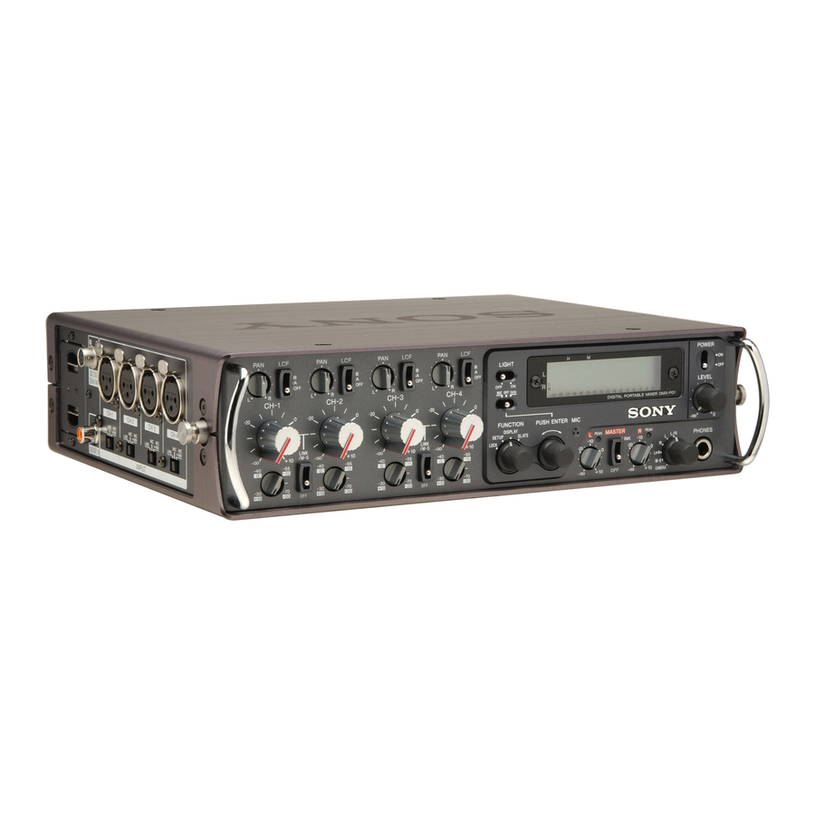
Overview The DMX-P01 is a portable digital mixer designed for professional electronic news gathering (ENG) and electronic field production (EFP). The DMX-P01 has a compact, lightweight body designed to be used in field production, making it ideal for use with digital video and audio recording media such as a camcorder and microphones, and so on. -
Page 5: Precautions
Full parameter controls on the front panel similar to those of analog mixers Controls and switches are logically laid out on the front panel to allow fast, easy and accurate setting adjustments. Also, the panel-lock function prevents you from operating the unit accidentally. -
Page 6: Using The Cd-Rom Manual
Using the CD-ROM Manual The supplied CD-ROM includes operating instructions (Japanese, English, French, German, Italian, Spanish and Chinese versions). CD-ROM System Requirements The following are required to access the supplied CD-ROM disc. • Computer: PC with Intel Pentium – Installed memory: 64 MB or more –... - Page 7 If you lose the CD-ROM disc or become unable to read its content, you can purchase a new CD-ROM disc to replace one that has been lost or damaged. Contact your Sony service representative. Trademarks • Intel and Pentium are registered...
-
Page 8: Location And Function Of Parts And Controls
Location and Function of Parts and Controls Front Panel 1 Input section 1 Input section 1 PAN control 2 LCF switch 5 LINK/M-S switch 4 Input gain control 3 Input level control 2 Digital function section 7 Output section 6 Headphones monitor mode switch 5 PHONES connector 1 PAN control Adjusts the mix level of the input... - Page 9 2 LCF (Low Cut Filter) switch Selects the frequency of the low cut filter of each channel. OFF: Select this position to deactivate the LCF switch. A, B: A cut-off frequency between 50 and 400 Hz at 48-kHz sampling frequency and between 70 and 400 Hz at 96-kHz sampling frequency can be assigned to each position.
- Page 10 Location and Function of Parts and Controls When M-S is selected on the 5. CH LINK/M-S sub-menu; The unit is in M-S mode. Select this position for M-S decoding when an M-S microphone is used. Connect channel 1 and channel 3 to the M side and channel 2 and channel 4 to the S side.
- Page 11 When you press the knob and release it instantly: When you press the knob and release it instantly, the sound or signal continues to be output. When you press the knob and release it again, output ceases. 3 LCD (Liquid Crystal Display) What is displayed depends on the setting of the FUNCTION switch.
- Page 12 Location and Function of Parts and Controls 5 ADJUST (PUSH ENTER) knob Used for menu operations. Select a menu by turning the knob and execute by pressing the knob. When the SLATE function is on, this switch acts as the slate signal output button.
-
Page 13: Left Panel
1 PEAK indicator Lights in red when the output signal reaches –3 dB from a clipping level. When the output compressors/limiters activate, this indicator lights to indicate the compressor/limiter operations, as follows. When the input level exceeds the preset threshold level, the output compressors activate and the indicator lights in orange. - Page 14 COAXIAL connector located on the right panel of the first DMX-P01. This unit is synchronized with the first DMX-P01 using the master clock signal extracted from the signal of this connector.
-
Page 15: Right Panel
Right Panel 1 PHONES connector 2 Analog output section 1 PHONES connector (3.5 mm TRS jack) Connects the headphones. The same signal as the one output from the PHONES connector located on the front panel is output. 2 Analog output section 1 ANALOG OUTPUT L/R connectors 2 CAMERA connector 3 LEVEL switch... - Page 16 CASCADE IN connector of the second DMX-P01 in a cascade connection for adding inputs. Note When two DMX-P01 mixers are used in the cascade connection, the sampling rate of both mixers should be matched. Set the same sampling rate using the SAMPLING RATE...
- Page 17 4 DC IN 10 - 15 V (external power input) connector (DC jack type)/ 5 DC IN 10 - 15 V (external power input) connector (XLR type 4-pin, male) Inputs the 10 to 15 V DC external power. Notes • An external battery other than BP-90 type battery cannot be connected to 4 DC IN 10 - 15 V (DC jack type) connector because the polarity of the...
-
Page 18: Connections
Note Before making connections, be sure to turn the power of any peripheral equipment off. Basic Connection An example of a basic connection where one DMX-P01 is used is as follows. Example 1 Boom microphone DMX-P01 to CH-1 INPUT Example 2... -
Page 19: Cascade Connection
UHF portable UHF portable transmitter 2 CH tuner a) Set the S/PDIF / CASCADE switch to CASCADE. b) Set the S/PDIF / CASCADE switch to S/PDIF. First DMX-P01 to COAXIAL to ANALOG OUTPUT L/R to COAXIAL to AES/EBU Second DMX-P01... -
Page 20: Display In The Display Mode
Display in the Display Mode The display mode, when the FUNCTION switch is set to DISPLAY, allows you to display all kinds of meters, the unit operating status and so on. In day-to-day operation, use the unit in the display mode. - Page 21 Input level meter Displays the pre-fader level of the input signal of each input connector. This display allows you to confirm whether or not the signal is input correctly. Input level meter for channels 1 and L: Pre-fader level of channel 1 R: Pre-fader level of channel 2 Input level meter for channels 3 and L: Pre-fader level of channel 3...
-
Page 22: Settings From The Setup Menu
Settings from the Setup Menu Setup Menu Structure You can set all sorts of parameters using the setup menu organized in the following 13 sub-menus. to the next page For details, see “Storing a scene” on page 27, and “Recalling a scene”... - Page 23 from the previous page...
-
Page 24: Basic Menu Operation
Settings from the Setup Menu Basic Menu Operation This section describes basic operating procedures for using a menu, taking the 9. PARAMETER LOCK sub- menu as an example. ADJUST knob FUNCTION switch Set the FUNCTION switch to SETUP. The sub-menu page of the SETUP menu that was used when the last menu operation was performed appears. - Page 25 When you want to perform an operation such as a reset (12. HOURS METER sub-menu), or a check of an item (3. CAMERA RETURN sub-menu) on the appropriate sub-menu, go to step Turn the ADJUST knob until the desired item blinks. Turning it to the right results in the cursor moving to the next item, and turning it to the left...
-
Page 26: Scene Recall Sub-Menu
Settings from the Setup Menu To move to another sub-menu When the cursor blinks beside the setting item just set, turn the ADJUST knob to the left until the return mark to the left of the top setting item appears and blinks. Press the ADJUST knob. -
Page 27: Scene Store Sub-Menu
2. SCENE STORE Sub- Menu This sub-menu allows you to store ten different parameter settings as a scene file from scenes nos. 0 to 9. Recalling the desired scene changes the unit to the desired setup immediately. Parameters stored in a scene file Parameters set on sub-menus 4 to 11. -
Page 28: Camera Return Sub-Menu
Settings from the Setup Menu 3. CAMERA RETURN Sub-Menu This sub-menu allows you to check whether or not signal transmission and reception are correctly performed between the unit and a camcorder by transmitting a 1-kHz reference signal from all of output connectors of the unit. -
Page 29: Ch Link/M-S Sub-Menu
5. CH LINK/M-S Sub- Menu This menu allows you select whether input channels 1 and 2 or channels 3 and 4 are set to LINK mode or M-S mode independently. 5. CH LINK/M-S sub-menu Turning the ADJUST knob to the right changes the setting item in the following sequence: CH1-2 t CH3-4. -
Page 30: Output Comp L Sub-Menu/8. Output Comp R Sub-Menu
Settings from the Setup Menu 7. OUTPUT COMP L Sub-Menu/8. OUTPUT COMP R Sub-Menu These sub-menus allow you to perform settings for compressors and limiters of the Left and Right channels. 7. OUTPUT COMP L sub-menu/ 8. OUTPUT COMP R sub-menu Turning the ADJUST knob to the right changes the setting item in the following sequence: THRESHOLD t RATIO t... -
Page 31: Parameter Lock Sub-Menu
Note When L-R LINK is set to ON, you cannot work on the 8. OUTPUT COMP R sub-menu. If you select the 8. OUTPUT COMP R sub-menu and press the ADJUST knob, the following message appears. 9. PARAMETER LOCK Sub-Menu This sub-menu allows you to lock parameters set on the following sub- menus. -
Page 32: Panel Lock Sub-Menu
Settings from the Setup Menu 10. PANEL LOCK Sub- Menu When the FUNCTION switch is set to LOCK, all of or some of the switches and controls on the front panel are locked and you cannot operate them. This sub-menu allows you to decide which switches and controls should be locked, from among the input level control, PAN control, LCF switch, L/... -
Page 33: Hours Meter Sub-Menu
Menu selection Meter VU meter PPM1 BBC-type meter PPM2 DIN-type meter PPM3 NORDIC-type meter PPM4 IEC-type 1-type meter dBFS dBFS meter Default setting: dBFS 12. HOURS METER Sub- Menu This sub-menu allows you to reset the accumulating time. 12. HOURS METER sub-menu When the time is reset, 00:00 appears in the upper row. -
Page 34: Using The Unit To A Camcorder
CAMERA connector of the unit using the 10-line multi cable with a 12-pin multi connector supplied with the unit. You can send signals from the unit and receive return signals from the DMX-P01 to CAMERA 12-pin multi connector (supplied) camcorder only if you use a multi cable. -
Page 35: Checking The Status Of A Connection
Checking the Status of a Connection The 3. CAMERA RETURN sub-menu allows you to check for misconnections of lines or other problems between the unit and the camcorder. This function can prevent trouble. To confirm the status of a connection, proceed as follows. - Page 36 Using the Unit to a Camcorder Turn the ADJUST knob to the right so that CHECK blinks on the sub-menu, and then press the ADJUST knob. The test signal is output and the unit starts checking the status of the connection. When the unit and the camcorder are connected correctly, the following window appears.
- Page 37 Messages stating the results of check Message Meaning SIGNAL OK Both left and right signals are connected correctly. L-R REVERSE The connection of the left and right signals are reversed. L-R NO SIGNAL Neither the left nor right signal is connected.
-
Page 38: Miscellaneous
Miscellaneous Preparing a Power Supply The unit can be powered in the following two ways: • Internal batteries Eight LR6 (size AA) alkaline batteries can be accommodated in the battery compartment. • External battery A lithium ion battery or nickel metal hydride battery which is connected to the DC IN 10 - 15 V connector on the right panel. - Page 39 Align eight new LR6 (size AA) alkaline batteries with the polarity markings and insert them into the battery compartment. Insert the batteries by aligning the polarity according to the markings on the battery compartment. + polarity Close the cover of the battery compartment and tighten the screw.
-
Page 40: Battery Life
Miscellaneous Battery life When the multi meter mode of the LCD is selected, the battery condition is shown on the LCD. To check the pwoer remaining in the internal batteries Shows the power remaining in the eight LR6 (size AA) alkaline batteries. -
Page 41: Replacing A Meter Scale Sheet
Replacing a Meter Scale Sheet When you change the meter displayed using the 11. METER SELECT sub- menu, you have to replace the meter scale sheet with the corresponding one. As the factory setting, the dBFS meter is selected and the meter scale sheet for the dBFS meter is attached to the unit. -
Page 42: Troubleshooting
If the problem persists, turn the unit off and consult your Sony dealer. Possible causes Batteries are inserted with the + and – polarities reversed. The batteries run low. - Page 43 Symptom An impression of stereo sound cannot be obtained. even when an MS microphone is used. Sound is not output from the R channels of the headphones. The sampling rate cannot be switched. The MASTER volume does not activate to adjust the level of the signal output from the COAXIAL connector.
-
Page 44: Pin Assignments Of Connectors
Miscellaneous Pin Assignments of Connectors INPUT connector XLR-3-31 (female) equivalent Pin No. Signal Remarks Ground of the audio signal input HOT of the audio signal input COLD COLD of the audio signal input ANALOG OUTPUT connector XLR-3-32 (male) equivalent Pin No. Signal Remarks Ground of the audio signal output... - Page 45 Pin No. Signal Remarks L HOT HOT of the left output of the master audio signal L COLD COLD of the left output of the master audio signal R HOT HOT of the right output of the master audio signal R COLD COLD of the right output of the master...
-
Page 46: Specifications
Storage temperature –20°C to 60°C (–4°F to 140°F) Continuous operation time Approx. 5 hours at the follwoing condition: Power supply; 8 LR6/ AA-size Sony alkaline batteries Sampling frequency; 48 kHz, Temparature; 25°C ( 77°F), LCD Light; off DC +48 V; off Mass Approx. -
Page 47: Supplied Accessories
AES/EBU (Digital) XLR-3-32 (male) equivalent, 110 S/PDIF / CASCADE (Digital) Phono jack, 75 PHONES (Analog) Stereo phone jack 3.5 mm TRS jack load impedance: or more, 300 mW or more (at a load) TAPE OUT (Analog) 3.5 mm TRS jack, load impedance: 10 k or more, Reference output level:... -
Page 48: Block Diagram
Block Diagram... - Page 49 Sony Corporation...