Table of Contents
Advertisement
Quick Links
Advertisement
Table of Contents

Related Manuals for Motorola R-2001A


Summary of Contents for Motorola R-2001A
- Page 1 Table of contents...
-
Page 3: Table Of Contents
TABLE OF CONTENTS Paragraph Page FOREWORD ................SECTION 1 1-1 Introduction ................1-1 SECTION 2 — DESCRIPTION 2-1 Description ................2-1 2-3 Microprocessor ................2-1 Display .................. 2-1 System Warnings ................. 2-1 Functions ................2-1 AM, FM, CW, DSB Signal Generation ............2-2 Simultaneous Modulation .............. -
Page 4: Paragraph Page
5-11 U. S. O r d e r s . 5-12 Canadian Motorola Electronics Company ............5-2 5-13 All Countries Except U. - Page 5 TABLE OF CONTENTS (CONT) Paragraph Page SECTION 7 - LOW VOLTAGE POWER SUPPLY (A1) General .................. 7-1 Input Power Control ..............7-1 DC Output Control ............... . Protection C i r c u i t r y .
- Page 6 TABLE OF CONTENTS (CONT) Paragraph Page SECTION 11 - RF SYNTHESIZER (A5) (CONT) 11-5 310-440 MHz Phase Locked Loop ............11-1 11-6 60.5 MHz Phase Locked Loop ............
- Page 7 TABLE OF CONTENTS (CONT) Paragraph Page SECTION 17 — RF INPUT MODULE (AH) 17-1 General ................. 17-1 17-2 Input Protection and Power Meter ............
- Page 8 LIST OF ILLUSTRATIONS Figure Page 1-1 Communications System Analyzer ............1-0 2-1 Accessories Supplied with A n a l y z e r ............2-4 Typical Communication System Analyzer Packaging ........
- Page 9 LIST OF TABLES Table Page 1-1 Physical Characteristics ..............1-2 Electrical Characteristics ..............1-1 1-3 Input/Output Characteristics ............. . . 1-5 2-1 Accessories Supplied with the Communication Systems Analyzer .
-
Page 10: Foreword
The Analyzer meets the shock and vibration requirements of EIA test RS152B, the same specifications met by Motorola mobile radios. This minimizes failures when the instrument is used in a mobile service van, and means it is as tough as the radios it services. -
Page 11: Communications System Analyzer
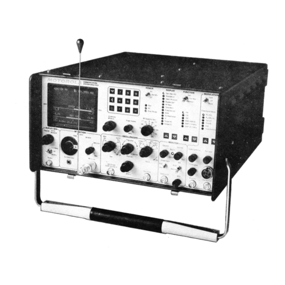
Figure 1-1. Communications System Analyzer... -
Page 12: Introduction
SECTION 1 1-1 INTRODUCTION 1-2 This section lists the physical, electrical, and input/output characteristics of the Communications stem Analyzer shown in figure 1-1. Table 1-1. Physical Characteristics Characteristic Description Length 20.75 inches (52.7 cm) Width 15.75 inches (40.0 cm) Height 8.25 inches (21.0 cm) Weight 48 pounds (21.9 kg) (Excluding Battery Pack) - Page 13 Table 1-2. Electrical Characteristics (Continued) Characteristic Description Amplitude modulation Range: 0 to 80% from 1 to 500 MHz Accuracy: ±10% of full scale from 0% to 50% AM External/internal frequency range: 5 Hz - 10 kHz (±1 dB) External input: Approximately 150 mV for 80%, BNC connector Modes: Internal, external, microphone or all simultaneously...
- Page 14 Table 1-2. Electrical Characteristics (Continued) Characteristic Description RF Wattmeter (Autoranging display) Frequency range: 1 MHz to 1000 MHz Power range: 1.0 watts to 125 wattts Accuracy: ±10%, 1 watt to 125 watts Over temp indicator Protection General Spectrum Analyzer Dynamic range >75 dB displayed, - 105 dBm to +30 dBm input range with step attenuator Frequency...
- Page 15 Table 1-2. Electrical Characteristics (Continued) Characteristic Description Digital Voltmeter Auto ranging digital display, 1, 10, 100, 300 volts full Readout scale. AC-dBm calibrated across 600 ohms. DC accuracy ±1% of full scale ±1 least significant digit ±5% of full scale AC accuracy 50 Hz to 10 kHz AC bandwidth...
-
Page 16: Input/Output Characteristics
10K ohms nominal, 150 mV typical for 20 kHz dev. FM or 80% AM Mic. Mic input provides bias and IDC limiting suitable for Motorola RTM 9000A handset. PTT switches R2001 from monitor to generate. 1 volt minimum for full screen deflection. Maximum input Ext Horiz 10 volts. - Page 17 0 dB position. Ext Wattmeter Characteristics suitable for Motorola ST-1200 series Wattmeter Elements 70 to 350 mV rms input required at 10 MHz, 10 MHz std in (rear panel) impedance greater than 50 ohms.
-
Page 18: Section 2 - Description
Sweep generator 2-3. MICROPROCESSOR. A Motorola M-6800 series microprocessor permits keyboard entry of data, autoranging of displays, fast frequency access, and permanent storage of often-used frequencies and codes. Generate and monitor RF frequencies, tone codes, and timing sequences can be programmed into a nonvolatile memory, saving time and eliminating entry errors. -
Page 19: Off-The-Air Monitor
The external modulation can be voice from a standard Motorola mobile radio microphone (which plugs into the front panel of the instrument), as well as a signal applied to the external BNC input. Separate controls are provided for independently setting the levels of the 1 kHz tone, the code synthesizer, and the external modulation sources. -
Page 20: Spectrum Analyzer
CRT display. 2-18. In-Line Power Measurement. Use of the Motorola ST-1200 series Wattmeter elements in conjunction with the analyzer's external wattmeter display provides measurement of forward and reflected antenna power on the CRT display. -
Page 21: Frequency Counter
2-21. Frequency Counter. The frequency counter measures inputs in a range from 10 Hz to 35 MHz. Its 5 digit auto-ranging output is displayed on the CRT and allows precise measurement and setting of offset oscillators, 35 kHz and 455 kHz pager IF's, PL frequencies and other external input signals. This function will also operate simultaneously with the generate or monitor receiver modes of operation. -
Page 22: Accessories Supplied With The Communication Systems Analyzer
Also used when charging optional battery pack. A X1 probe with attachments for general servicing. Oscilloscope probe RTL-4058A Allows use of Motorola ST-1200 series in-line watt- In-line wattmeter adapter RTL-4055A meter elements for direct measurement and display of forward and reflected transmitted power. - Page 23 Table 2-2. Optional Equipment for Use with Analyzer (Cont) Equipment Motorola Part No. Battery pack RTP-1002A 13.6 volt battery and charger attaches to back of the unit. Provides one hour of continuous operation. Cannot be used with IEEE-488 or Blower options.
-
Page 24: Section 3 - Installation
SECTION 3 INSTALLATION 3-1. PACKING INFORMATION 3-2. The unit is packaged in a fiberboard carton and protected by foam pieces as shown in figure 3-1. The unit is first packed in a cardboard container and then thiscarton is packed in asecond, larger cardboard container, for further protection. -
Page 25: Battery Pack
NOTE The unit is set for 110-130 Vac operation from the factory. For operation from 1 GO- 110 Vac or 200-260 Vac, the voltage selection card must be readjusted before connection to the power source. This is accomplished by the following procedure: 1. -
Page 26: General
SECTION 4 OPERATION 4-1. GENERAL 4-2. This section contains information tor the operation of the Communication System Analyzer. 4-3. CONTROLS, INDICATORS, AND CONNECTORS 4-4. The analyzer controls, indicators, and connectors are shown in Figures 4-1 through 4-3 and listed with their functions in Table 4-1. -
Page 28: Controls, Indicators, And Connectors, Left Side Panel
Figure 4-2. Controls, Indicators, and Connectors, Left Side Panel Figure 4-3. Controls, Indicators, and Connectors, Rear Panel... - Page 29 Table 4-1. Controls, Indicators, and Connectors (Cont) Item Description Function Eleven position switch Allows automatic scan of the generated or the RF Scan (Hz/Sec) monitored frequency. The switch setting indicates switch rate of frequency change. The rate is 5 steps per second, with frequency steps of 100 Hz, 1 kHz, 10 kHz, 100 kHz and 1 MHz.
-
Page 30: Monitor
Table 4-1. Controls, Indicators, and Connectors (Cont) Item Description Function d. Duplex Gen — The duplex generate and monitor frequencies are displayed. The depth of modulation on the generator output or on the received carrier is indicated for the generate and monitor modes respectively. For this display, the function switch only selects which modulation reading is dis- played. - Page 31 Table 4-1. Controls, Indicators, and Connectors (Cont) Item Description Function b. Pwr Mon - equipment monitors input signals with the input terminated into the internal power meter. This position must be used for inputs of 0.2 watts and greater. c. Monitor - equipment monitors input signals with the input terminated into the receive mixer.
- Page 32 Table 4-1. Controls, Indicators, and Connectors (Cont) Item Description Function FRONT PANEL (fig. 4-1) (Cont) b. Off - Turns off signal. When the mode is DPL or DPL Inv, returning the switch to Off from Cont produces a 133 Hz tone burst for a 120 ms duration.
- Page 33 Indicates Tone A/Tone B signaling sequence will be output. See Tone Memory Table example, figure 4-9. f. Tone Remote indicator Indicates access sequence for Motorola Repeater will be output. Tone A and B frequencies are entered from the keyboard on the Tone Memory Display.
- Page 34 Table 4-1. Controls, Indicators, and Connectors (Cont) Item Description Function Output connector for all modulation signals Mod Out connector BNC connector (all signals combined). Potentiometer Controls speaker output level. Volume control Two-position switch BW switch In either Pwr Mon or Monitor modes selects IF bandwidth.
- Page 35 Table 4-1. Controls, Indicators, and Connectors (Cont) Item Description Function Horiz Vernier control Potentiometer Horizontal sweep rate Vernier or external hori- zontal input gain Vernier. Calibrated position Is fully clockwise. Ext Horiz BNC connector Allows external horizontal inputs for oscilloscope. Trig Level Stacked concentric Selects oscilloscope trigger level and trigger...
-
Page 36: Ext Wattmeter
Also serves as RF input level step attenuator in monitor and spectrum analyzer modes. Allows input from Motorola ST-1200 series in- Ext Wattmeter Connector line wattmeter elements for measurement and CRT display of forward and reflected trans- mitted power. - Page 37 Table 4-1. Controls, Indicators, and Connectors (Cont) Item Description Function DC IN power 4-pin connector Connects to DC prime power source connector AC power connector 3-pin connector Connects to AC prime power source. Internally patched to accommodate either 100-110 VAC, 110-130 VAC, 200-220 VAC or 220-260 VAC.
- Page 38 0.5 ppm achievable with the above method. NOTE An external time base input is also provided on the rear panel. R-2001A ";i.:Tor an B I E S . O O O O MH: • FREQUENCY FUNCTION INPUT MBIT;,...
-
Page 39: Duplex Generation
Switch function to power monitor and connect repeater transmitter (under 125 watts) directly to the RF In/Out connector to read power and frequency error, as well. R-2001A REPEATER XMIT FUNCTION - I.-'LE'. n n m i o F B- w.i.ocio nn:... -
Page 40: Frequency Counter
4-10. FREQUENCY COUNTER. The frequency Counter measures inputs in a range from 10 Hz to 35 MHz. The in put to the frequency counter is through theVert/Sinad/DVM/Counterin, BNC connector (located in the OSCILLOSCOPE section of the front panel). The counter sensitivity is controlled by the scope Vert switch. The following shows the minimum sensitivity for each switch setting: Switch setting Sensitivity... - Page 41 The frequency indicated at the top of the screen is now that of the desired incoming signal. It can also be monitored for call signs, etc. NOTE The spectrum analyzer is functional but uncalibrated for level measurements in Power Monitor mode for transmitter testing with the built-in 125 watt 50 ohm load. (Observe "RF LOAD OVERTEMP"...
-
Page 42: Simultaneous Generate And Measurement Operations
4-13. EXT WATTMETER. When the analyzer DISPLAY is set to the Ext Wattmeter mode and the Motorola RTL-4055A in-line wattmeter adapter (supplied) is connected to the Ext Wattmeter jack the analyzer measures both forward and reflected power. The power rating of the wattmeter elements (Motorola ST-1200 series"), to be used, are displayed on the CRT. -
Page 43: Meter With Crt Display
Adjust 1 kHz level for 3.0 kHz deviation and RF level for 12 dB SINAD indication. (The mobile radio audio output may be set to the desired level using the DVM AC mode.) Read receiver SINAD sensitivity in microvolts or dBm. R-2001A FREQUENCY ;EI."'-'E Ff B •... -
Page 44: Test Setup For Pager And Alert Functions With Crt Display
MIKE •ONE nEnn(Y SED S E L E C T ) g R-2001A BTONE ATONE B ' O S S 5 . 0 . H Z t > 0 5 1 0 , 5 H Z FREQUENCY -*• " FREQUENCY •,... -
Page 45: Test Setup For Using Dvm And Signal Generate With Crt Display
R-2001A FUNCTION -FREQUENCY I C N I T D E FM g) 1 5 1 . 9 5 5 0 m: VERT/SINAD INPUT UflTTS 0.00 RF IN/OUT DVM/COUNTERIN ANALOG - 1 .( t B M ' . ; flC .(45 »- DVM READING... -
Page 46: Section 5 - Maintenance
Most in-warranty repair are performed at the center. Exceptions include repairs on some equipment not manufactured by Motorola which are performed by the original supplier under the direction of the Test Equipment Repair Center. Out-of-warranty service is performed on a time and materials basis at competitive rates and the maximum turn-around goal is less than ten working days. -
Page 47: Orders
3125 Steeles Avenue East Willowdale, Ontario Phone: 516-499-1441 TWX: 610-492-2713 Telex: 02-29944LD 5-13. All Countries Except U.S. and Canada MOTOROLA INC., OR MOTOROLA AMERICAS, INC. International Parts 1313 E. Algonquin Road, Schaumburg, Illinois 60196 U.S.A. Phone: 312-397-1000 TWX: 910-693-1592 or 1599... -
Page 48: Major Assemblies
5-14. MAJOR ASSEMBLIES 5-15. The Communication System Analyzer is designed for ease of maintenance. Most of the circuitry is on seven plug-in circuit boards. A list of all subassemblies is given in table 5-1. The assembly locations are shown in figures 5-1 and 5-2. Table 5-1. -
Page 50: Theory Of Operation
5-16. THEORY OF OPERATION 5-17. General 5-18. The operation of the Communications System Analyzer can be divided into nine basic functions; Generate, Power Meter, Monitor, Duplex Generator, Code Synthesizer, Frequency Counter, Digital Voltmeter (DVM), Oscilloscope, and Sinad Meter. The general operation of the unit will simultaneously incorporate the basic functions to provide the total capability of the system. -
Page 53: Generate Mode Block Diagram
10 MHz FREQUENCY INPUT STANDARD Figure 5-4. Generate Mode Block Diagram 5-27. The Frequency Standard module (A13) contains a 10 MHz standard oscillator with buffering and switching to provide a 10 MHz signal to the EXTERNAL 10 MHz OUTPUT and to the RF Synthesizer (A5). A provision is made for the application of an EXTERNAL 10 MHz INPUT which causes the internal standard to shutdown and the EXTERNAL 10MHz INPUT to be switched to the EXTERNAL 10 MHz OUT and to the RF Synthesizer. -
Page 54: Power Meter
5-30. The SYNTH RF signal is amplified and leveled in the RF Input module (AH). The signal level at the output of the wideband amp is detected and compared to the AM MOD & DC REF signal from the front panel level control. -
Page 55: Monitor Mode
10.7 MHz IF RF INPUT PWR OVER TEMP ^ INPUT PROTECTED Figure 5-5. Power Meter Block Diagram 5-38. A sample of the RF voltage being applied to the RF Load is detected by the Power Detector to give a DC output proportional to the peak RF voltage. -
Page 56: Monitor Mode Block Diagram
Figure 5-6. Monitor Mode Block Diagram 5-44. The 10.7 MHz difference signal at the IF port of the receive mixer is amplified and selected by the first IF Amplifier and Filter. The Amplifier provides sufficient gain so that the overall gain of the RF Input module is 10 ±2 dB. -
Page 57: Duplex Generator
5-47. The output signal from the IF filter has two possible paths. The path to the Log Amplifier and Detector provides the spectrum analyzer capability. The other path is the linear IF Amplifier for AM, FM, and SSB demodulation. The output level of the Amplifier is detected to give amplitude modulation and to provide the AGC control on the IF amplifier. -
Page 58: Code Synthesizer
1 kHz Level Control. 5-61. Two sources of external modulation are possible. A standard Motorola microphone interface jack on the front panel and a BNC front panel jack are provided. The microphone input is connected to an IDC circuit .for peak limiting. -
Page 59: Code Synthesizer Block Diagram
' • "• CONTROL A6 AUDIO'S YNTI ^ESIZER ROCESSOR |" AUDIO PRGM ^ w • A8 IEEE ^TE? SYNTH ATTEN . 4 0 PRGM CODE ATTEN <> — SYNTH 42 1 KHz —— PRGM BPFL (1 KHz) ATTEN 1KHz < ^ IEEE MIC-2. -
Page 60: Frequency Counter
5-65. Frequency Counter 5-66. Three possible signal sources are made available to the frequency counter for frequency determination. Two of the inputs are from internal system points for the determinations of the offset frequency (OFFSET), and the monitored carrier error frequency (IF/BFO). The third input is the external input (FREQ CNTR INPUT) on the front panel. -
Page 61: Digital Voltmeter (Dvm) Block Diagram
Figure 5-10. Digital Voltmeter (DVM) Block Diagram 5-73. Switching for the DVM input is contained on the Scope/DVM Control module (A3). One of ten internal measurement points may be selected for measurement. The switching action is controlled by the processor and is performed as required to obtain the information on the CRT. -
Page 62: Oscilloscope
5-76. The RF INPUT POWER and OVERTEMP signal lines from the RF Input module provide the processor inputs for the internal wattmeter. (Paragraph 5-38). External wattmeter element inputs (EXT FWD PWR and EXT RFL PWR) from the front panel jack provide the information for the external wattmeter display. 5-77. -
Page 63: Oscilloscope Block Diagram
Figure 5-11. Oscilloscope Block Diagram 5-87. The horizontal amplifier input is selected between external and internal scope functions. External functions, Time base Generator or external horizontal input, are switched to a sumation amp where the HORIZONTAL POSITION signal from the front panel is added. The resulting DC offset positions the display horizontally on the CRT. -
Page 64: Sinad Meter
preamp on. the Front Panel Interface module (A12). The preampprovittes (he required horizontal input sensitivity and buffers the signal to the select switch on the Scope Amplifier module. 5-90. Internal horizontal signals, Sweep Generator and Character Sweep outputs, are selected on the Scope/DVM Control module (A3). -
Page 65: Alignment Procedure
5-103. The test equipment or its equivalent listed in table 5-3 is required for the basic procedure. The additional equipment required for the extended procedure is listed in table 5-4. Table 5-3. Basic Test Equipment Required Description Model Motorola R1004A 'Oscilloscope Test Point Shorting Jumper Nonmetallic Alignment Tool *A R2001A is a suitable substitute... -
Page 66: Preparation For Alignment
Table 5-4. Extended Test Equipment Required Description Model Motorola R1004A 'Oscilloscope Motorola R1001A 'Digital Voltmeter Motorola R1201A *RF Signal Generator Boonton 82AD •Modulation Meter Receiver Test Cover Motorola 15-P01324V001 Motorola 67-P01322V001 Extender Card Set "A R2001A is suitable for use in place of these separate equipments. - Page 67 5-107. CRT intensity Bias Select the Scope DC Display and the Ext Horiz. Input mod» Set the Intensity Control fully counter clockwise. CAUTION Do not let a dot stay in one place on the CRT screen for more than 30 seconds as a permanent burn in the phosphor will occur.
- Page 68 5-112. CRT Horizontal Gain Connect the Mod Out Jack to the Ext Horiz Jack on the R2001A front panel. Set the R2001 A for the Generate FM Function and the Scope DC Display. Set the Horiz Control for Ext Horiz input. Turn the Code Synthesizer off/the Ext Level offhand the 1 kHz Level up about half way. Connect an oscilloscope with a calibrated vertical input-to TP1 on the Scope Amplifier Board.
-
Page 69: Front Panel Interface Alignment Points
Figure 5-14. Front Panel Interface Alignment Points 5-115. DVM Zero Select the DVM Display and the DC Mode on the R2001A. Short the center conductor of the DVM Input Jack to ground. Adjust the DVM Zero (Coarse) and the DVM Zero (Fine) Potentiometers on the Front Panel Interface Board (Figure 5-14) for a zero reading on the DVM Display. - Page 70 PEAK DETECTORS ZERO NE6ATIVE POSITHE Figure 5-15. Scbpe/DVM Control Alignment Points Adjust the Coarse Time Base Calibration Potentiometer on the Scope Amplifier Board (Figure 5-16) so that one cycle of the displayed waveform occurs in 5 cm along the horizontal axis. Use the Vertical and Horizontal Position controls to center and to move the waveform so that the 5 cm are measured in the middle of the screen to avoid nonlinearities near the edge of the CRT.
-
Page 71: Extended Alignment Procedure
5-118. Extended Alignment Procedure 5-119. DVM Remove the top and bottom covers of the-R2001A. Connect the R2001Atoa primary power source and turn it on. Allow approximatly 15 minutes warm up before proceeding with the alignment procedure. Short the center conductor of the DVM Input Jack on the front panel to ground. Connect an external DVM with a floating input between pin 1 and pin 6 of J3 on the bottom side of the motherboard. -
Page 72: Processor I/O A/D Alignment Points
Repeat paragraphs 5-119.3 and 5-119.4. Disconnect the external DVM. With the DVM input jack still shorted adjust the A/D Zero Potentiometer on the I/O Board (Figure 5-19) for a O.tfVDC'reading on the R2001ACRT display. CAUTION Do not use the card extender while aligning the Processor I/O board. 10. -
Page 73: Scope/Dvm Control Char Sweep And Sinad Alignment Points
5-120. Character Generator Perform the Basic Alignment Procedure of para 5-105. Turn the R2001A off and extend the Scope/DVM Control Board using the 100 pin extender card. Turn the R2001A on and select the Monitor FM Function and the Gen/Mon Mtr Display. Adjust the Horizontal Character Sweep Width Potentiometer on the Scope/DVM Control Board (Figure 5-20) so that the right-hand edge of the CRT character display is approximately 4.2 graticule divisions to the right of the graticule center line. - Page 74 AHernatety ad/usl She Iwo SWAD Noich polenf/ome'ters on 8ie Scope/DVW Coniro) Board iF/gare 5-20) for a maximum SINAD reading on the CRT display. A reading greater than 30 dB should be obtained. Turn the system power off and reinstall the Scope/DVM Control Board into the R2001A. 5-122.
-
Page 75: Checkout Procedure
5-129. Test Equipment Required 5-130. The test equipment listed in table 5-5 or its equivalent will be required to perform the checkout procedure. Table 5-5. Test Equipment Motorola R-1201A *RF Signal Generator Motorola S-1339A "RF Power Meter Motorola R-1013A *SINAD Meter Boonton 82AD "Modulation Meter... -
Page 76: Procedure
5-131. Procedure 5-132. Power On Check that the AC input power select card is in the 120 V postion. Connect the Unit UnderTest (UUT) to a 120 VAC line source with the front panel power switch off. Verify the presence of an AC indication on the front panel. - Page 77 5-136. Frequency Counter Set the UUT to the Gen CW Mode with an output frequency of 35 MHz at a level of 0 dBm as displayed ontheGen/Mon Mtr display. Connect the RF In/Out Jack to the Counter In Jack of the UUT. Select the Frequency Counter Display and verify a frequency reading of 35 MHz.
- Page 78 5-140. Scan Mode Set the UUTfortheGen/Mon Mtr display. Verify the proper operation of each of the RF Scan, switch positions. 5-141. Generate Mode Set the UUTforthe Generate FM Mode at 200 MHz'and select the Gen/Mon Mtr display. Verify an RF level output display on the CRT.
- Page 79 5-142. Power Monitor Mode Set the UUT to the Power Monitor Mode. Set the RF Step Attenuator to the 30 dB position, and select the Gen/Mon Mtr Display. Connect the RF power source to the RF In/Out Jack. Key the power source and verify a correct power reading on the CRT display.
-
Page 80: System Troubleshooting
5-144. Spectrum Analyzer Set the UUT for the Monitor Function of 300 MHz the Spectrum Analyzer Display, and 0 dB input attenuation. Set at 300 MHz. Connect the Signal Generator to the RF I n/Out Jack on the UUT. Verify a spectral amplitude of -30 dBm ±5 dB on the CRT display. - Page 81 Table 5-6. System Troubleshooting (Cont) Test Paragraph Fault Troubleshooting Procedure 5-132 System won't turn on 1. Disconnect the high voltage supply from the low voltage supply at A10P1. Check for +7.9 VDC at pin 1 of J2 on the low voltage supply and for+12 VDC at pin 2.
- Page 82 Table 5-6. System Troubleshooting (Cont) Fault Troubleshooting Procedure 3. Check for the DPL signal at TP6 of the Audio Synthesizer. If not present replace the Audio Synthesizer (A6). 4. Check for the DPL signal at TP4 of the Scope Amplifier module (A2). If not present replace the Scope/DVM control module (A3).
- Page 83 Table 5-6. System Troubleshooting (Cont) Test Paragraph Fault Troubleshooting Procedure NOTE The DVM AC signal from the external input is multiplexed with the other signals to be mea- sured. Thus only short bursts of the input signal will be observed at TP8. If signal is not present at TP8 replace the Scope/DVM Control module.
- Page 84 Table 5-6. System Troubleshooting (Cont) Fault Troubleshooting Procedure. 2. If sync pulse and the syn present lines are okay replace the Scope Amplifier module (A2). SINAD meter inoperative 1. If the DVM mode checks okay replace the Scope/DVM Control module (A3). 2.
-
Page 85: Test Point Identification
Table 5-6. System Troubleshooting (Cont) Test Paragraph Fault Troubleshooting Procedure 5-144 No spectrum analyzer sweep 1.. Check pin 6 of the RF Synthesizer module (A5) for a 50 Hz square wave. If not present replace the RF Synthesizer module. 2. If 50 Hz signal is present replace the Scope/ , DVM Control module (A3). - Page 86 Table 5-7. Test Point Identification Signal Description Test Point No. Module Synth. D/A Output Ground Composite Modulation Audio Composite External Mod. Audio Synthesizer Clock 104, 857.6 Hz 1 kHz Modulation Source A/D Input Unfiltered 10.245 MHz T.V. Processor I/O DVM/Freq. Counter Select Frequency Counter Input Not Used Ground...
- Page 87 SECTION 6 SYSTEM INTERCONNECT AND PARTS LISTS...
-
Page 92: General
SECTION 7 LOW VOLTAGE POWER SUPPLY (A1) 7-1. General. The low voltage power supply converts either an AC line input or a DC supply input to the DC operating voltages required by the system. Appropriate protection circuits are incorporated within the supply to protect both the supply and the system in vhe event of certain common malfunctions. -
Page 93: High Voltage Supply Control
7-10. Short circuit protection is implemented by monitoring the current in the primary winding of theoutput transformer. If a secondary output is shorted the primary current will increase significantly causing the overcurrent detector to pull the control line low shutting down the supply. However, with the supply shut down primary current will cease and the overcurrent detector will release the control line. -
Page 103: General
SECTION 8 SCOPE AMPLIFIER (A2) 8-1. General. The Scope Amplifier module contains the horizontal and vertical deflection amps, the horizontal timebase generator, focus and intensity control circuitry, and miscellaneous CRT bias adjustments. A block diagram of the Scope Amplifier module is shown in figure 8-1 with its schematic shown in figure 8-2. 8-2. -
Page 109: General
SECTION 9 SCOPE/DVM CONTROL MODULE (A3) 9-1. General. A primary function of the Scope/DVM Control Module is to route the required measurement and viewing signals to the DVM and scope circuitry. A large portion of the displayed data is determined by the DVM measurements on internal signal points. -
Page 110: Khz Pll.
detection filtering. A sample of the BFO signal is made available to the frequency counter on the IF/BFO FREQ line for sideband frequency error determination. 9-8. 455 KHz PLL. For monitor frequency error determination a 455 KHz Phase Locked Loop (PLL) is used to filter and to shape the IF signal. -
Page 111: Peak Detector
9-17. Peak Detector. Each of the modulation and demodulation inputs can be selected to the peak detecting circuitry for the determination of % AM or kHz deviation. The peak detector circuitry provides DC outputs equal to the negative and positive peak values of the input signal relative to the average DC level of the signal. -
Page 112: Sinad Detection ....................................:
9-21. SINAD Detection. The SINAD of a signal on the DVM FROM RNG SW line is determined by taking the ratio of the input to the output signal power on the 1 kHz Notch Filter. Signal power is determined by Rectifier and Filter circuits whose outputs are DC levels proportional to the input signal levels. -
Page 120: General
SECTION 10 RECEIVER (A4) 10-1. General. The Receiver down converts the 10.7 MHz first IF signal to 455 kHz. Following the down conversion a linearoralogarithimic IF amplifier provide the gain prior to AM and FM detectors or the spectrum analyzer detector respectively. Post detection filtering provides the wide or narrow band responses for the audio outputs. -
Page 121: Logarithmic Amplifier And Detector.
Control module for modulation determination, the DEMOD OUT signal goes to the front panel jack, and the VOL CNTL ADD provides the drive to the speaker audio amplifier. 10-10. Logarithmic Amplifier and Detector. For the spectrum analyzer function the logarithmic IF amplifier processes the input signal level over an 80 dB range. -
Page 126: General
SECTION 11 RF SYNTHESIZER (A5) 11-1. General. The RF Synthesizer provides an RF signal source for the frequency range from 10kHzto1 GHz in 100 Hz steps. The output frequency is programmed by the processor through the RF control bus and is phase locked to the 10 MHz frequency standard. -
Page 127: Mhz Phase Locked Loop
11-9. 500-1000 MHz Phase Locked Loop. The 500-1000 MHz output is locked to either the sum or the difference of the 310-440 MHz and 60.5 MHz loop output frequencies. In the locked condition, mixing the divide by two output of the 500-1000 MHz VCO's with the 310-440 MHz signal gives a difference frequency equal to the 60.5 MHz output. -
Page 142: General
SECTION 12 AUDIO SYNTHESIZER (A6) 12-1. General. Generation, processing, and control of modulation audio is the function of the Audio Synthesizer module. Three modulation signals, private line, digital private line, and a fixed 1 kHz, are generated on the board. Processing for external microphone and BNC jack audio inputs as well as sumation of all modulation sources to form a composite source is provided. -
Page 143: Khz Tone.
12-9. A bandpass filter following the shift register output removes the higher frequency components of the digital signal. The filtered DPL signal is then applied to the select switch. For the DPL off code (133 Hz tone), the processor switches the INT MOD line to the PL output so that a 133 Hz sinewave is output. 12-10. -
Page 148: System Control Bus Interface
SECTION 13 PROCESSOR I/O MODULE (A7) 13-1. General. Frequency Counter and DVM functions with their processor interface as well as the processor interface for the two system control buses are contained on this module. Additionally, circuitry to complete the 10.245 MHz phase locked loop, and to zero beat the incoming carrier are also on this board. A block diagram of the processor I/O module is shown in figure 13-1 with its schematic shown in figure 13-2. - Page 149 13-9. The Counter Control circuitry responds to a START pulse from the processor to gate the output of the Select Switch to the Accumulator for a time period determined by the Gate Time Generator. When the gate time has ended, or if the accumulator overflows, the Counter Control signals the processor on the END line that the count is complete.
-
Page 156: General
SECTION 14 IEEE INTERFACE MODULE (A8) 14-1. General. Remote control of the system is possible using a IEEE-488 bus and the IEEE Interface Module. The Interface Module provides the interface for the 488 bus and provides for processor control of most of the functions normally controlled from the front panel. - Page 161 15-2. Processor. A Motorola MC6802 microprocessor is the central part of the processor. The microprocessor then accesses and controls the rest of the processor via three signal buses. The sixteen bit address bus (AO-A15) determines which device on the bus the microprocessor will access. Data that will be read from or written to the accessed device is contained on the seven bit data bus (DO-D7).
- Page 162 15-8. Seven bit words representing one of 128 possible characters are stored in RAM for each character location on the CRT. The character generator sequentially accesses each RAM location in synchronization with the raster scan and creates a pulse modulation sequence in response to the character data that results in the character being displayed on the CRT.
- Page 170 SECTION 16 HIGH VOLTAGE POWER SUPPLY (A10) 16-1. General. Bias and drive voltages for the CRT are supplied by the High Voltage Supply. The supply converts a nominal 8 VDC input level to output voltages of +4 kV and -2 kV. Circuits for low voltage control of the intensity and focus grids is also provided.
-
Page 175: Input Protection And Power Meter
SECTION 17 RF INPUT MODULE (AH) 17-1. General. The RF Input Module is subdivided into three isolate circuits; input protection and power meter, wideband amplifier and frequency converter and duplex generator. A block diagram of the RF Input Module is shown in figure 17-1 with its schematic shown in figure 17-2. 17-2. - Page 176 17-8. For DSBSC generation the modulation audio is applied to the IF port of the input mixer through an isolation network. With the output of the wideband amplifier switched to the local oscillator port, a DSBSC signal is present at the RF port. Switching the Step Attenuator to the RF output port makes the DSBSC signal available at the RF output.
-
Page 188: General
SECTION 18 FRONT PANEL INTERFACE MODULE (A12) 18-1. General. Input buffers and output latches for front panel control and display interface to the processor are contained on the Front Panel Interface Module. Buffering and ranging circuits for the external scope vertical, SINAD, DVM, Frequency Counter, and external scope horizontal inputs is also contained on this module. - Page 194 SECTION 19 10 MHz FREQUENCY STANDARD MODULE (A13) 19-1. General. The frequency Standard Module provides a stable 10 MHz source and the interface for an external 10 MHz input. A block diagram of the Frequency Standard Module is shown in figure 19-1 with its schematic shown in figure 19-2.
- Page 204 SECTION 21 BLOWER ASSEMBLY (A15) 21-1. For continuous high ambient temperature operation or with the IEEE control option, the blower option provides additional cooling for the system. The blower as received from the factory will run whenever the unit is connected to the AC line. However, a jumper shorting out a thermostat in the blower assembly may be removed so that the fan only operates when high temperature conditions exist.
- Page 206 488 specification. Application software is the user's responsibility as dictated by the controller selected, although interface and application assistance is available from Motorola. 22-5. The IEEE option package consists of an IEEE Interface module (A8) with a rear panel connector, an...
- Page 208 22-7. IEEE-488 BUS STRUCTURE 22-8. The following discussion briefly describes the 488 Bus operation. It is not a complete definition of the total bus structure or capability. For complete information a copy of IEEE Standard 488 should be obtained. 22-9. Bus Signals. The IEEE-488 Bus consists of 16 parallel lines. The lines are divided into three groups. Lines DI01-DI08, Data Input Output, form the 8-bit data bus for the bidirectional transfer of control and ASC II characters.
- Page 209 22-15. Command Structure. Each command consists of a two letter definition prefix followed by a numeric data field. The data field will vary in length and structure according to the definition prefix as shown in table 22-3. Spaces may be inserted anywhere in the command but are not required. Each letter or number of a command is transferred from the bus controller to the^nalyzer in ASCII format.
-
Page 211: Command Strings
22-23. The following are examples of correct data fields for the value 12.34: 0.1234 E+2 +0.1234 E2 1234 E-2 1234. E-2 +12.34 12.34 E +1234 E-2 12.34 EO 22-24. Command Strings. A command string consists of either a single command or multiple commands in succession with or without embedded spaces. -
Page 212: Programming Commands
22-34. Exponent Magnitude. The exponent magnitude is a single digit with a value from 0 to 9. The digit indicates the negative power of ten that is to be multiplied with the data value to obtain the units listed in table 22-3. -
Page 214: Service Requests
22-43. The format of the error message is: ERROR nn (CR)(LF) The two digit number nn defines the error condition as listed in table 22-5. The carriage return (CR) and line feed (LF) characters are the termination sequence used by analyzer whenever it transmitts information. All characters are ASC II coded. -
Page 215: Programming Considerations
22-46. Programming Considerations. The flexibility of the IEEE-488 option is reflected in the number of programming commands. To use these effectively and efficiently, certain programming practices should be followed. The following paragraphs present the major considerations for effective programming. 22-47. Generate Mode. For accurate level control it is best to specify the generate frequency priortotheRF output level. -
Page 216: General
22-52. Measurements. To obtain correct monitor mode data it is necessary to first set the frequency, bandwidth, and image prior to making the reading. Thus, it is a good practice to always place the request for a reading as the last command in the string. For example the command string: CMRNRHGF95.5RET selects the monitor mode, narrowband, high image, and 95,5 MHz center frequency.