Panasonic U-4LE1R8 Service Manual
Mini vrf system, r410a
Hide thumbs
Also See for U-4LE1R8:
- Installation instructions manual (136 pages) ,
- Operating instructions manual (68 pages)
Table of Contents
Advertisement
Model No.
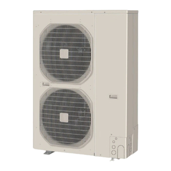
Outdoor Unit
Class
4HP
U-4LE1R5
Model Name
U-4LE1R8
HP = horsepower
Indoor Unit
Class
22
4-Way Cassette
U1
S-22MU1E5
Y1
4-Way Cassette 60×60
S-22MY1E5
L1
2-Way Cassette
S-22ML1E5
1-Way Cassette
D1
Low Silhouette Ducted
S-22MF1E5
F1
M1
Slim Low Static Ducted
S-22MM1E5
T1
Ceiling
S-22MK1E5
K1
Wall Mounted
Concealed Floor
R1
S-22MR1E5
Standing
P1
Floor Standing
S-22MP1E5
High Static Pressure
E1
Ducted
85464849309000
5HP
6HP
U-5LE1R5
U-6LE1R5
U-5LE1R8
U-6LE1R8
28
36
45
S-28MU1E5
S-36MU1E5
S-45MU1E5
S-28MY1E5
S-36MY1E5
S-45MY1E5
S-28ML1E5
S-36ML1E5
S-45ML1E5
S-28MD1E5
S-36MD1E5
S-45MD1E5
S-28MF1E5
S-36MF1E5
S-45MF1E5
S-28MM1E5
S-36MM1E5
S-45MM1E5
S-36MT1E5
S-45MT1E5
S-28MK1E5
S-36MK1E5
S-45MK1E5
S-28MR1E5
S-36MR1E5
S-45MR1E5
S-28MP1E5
S-36MP1E5
S-45MP1E5
Mini VRF System
56
73
90
S-56MU1E5
S-73MU1E5
S-56MY1E5
S-56ML1E5
S-73ML1E5
S-56MD1E5
S-73MD1E5
S-56MF1E5
S-73MF1E5
S-90MF1E5
S-56MM1E5
S-56MT1E5
S-73MT1E5
S-56MK1E5
S-73MK1E5
S-56MR1E5
S-71MR1E5
S-56MP1E5
S-71MP1E5
S-73ME1E5
106
140
S-106MU1E5
S-140MU1E5
S-160MU1E5
S-106MF1E5
S-140MF1E5
S-160MF1E5
S-106MT1E5
S-140MT1E5
S-106MK1E5
S-106ME1E5
S-140ME1E5
SM830209-00
REFERENCE NO.
160
Advertisement
Chapters
Table of Contents

Related Manuals for Panasonic U-4LE1R8


Summary of Contents for Panasonic U-4LE1R8
-
Page 1: Indoor Unit
Mini VRF System Model No. Outdoor Unit Class U-4LE1R5 U-5LE1R5 U-6LE1R5 Model Name U-4LE1R8 U-5LE1R8 U-6LE1R8 HP = horsepower Indoor Unit Class 4-Way Cassette S-22MU1E5 S-28MU1E5 S-36MU1E5 S-45MU1E5 S-56MU1E5 S-73MU1E5 S-106MU1E5 S-140MU1E5 S-160MU1E5 4-Way Cassette 60×60 S-22MY1E5 S-28MY1E5 S-36MY1E5 S-45MY1E5... -
Page 2: Special Precautions
Permission from the power supplier is required when Carefully refer to the wiring diagram and these installing the U-4LE1R8, U-5LE1R8, U-6LE1R8, instructions when wiring. Improper connections and outdoor units that are connected to a 16 A distribution inadequate grounding can cause accidental injury or network. - Page 3 When Installing… When Servicing • Turn the power OFF at the main power box Select an installation location which is rigid and strong (mains) before opening the unit to check or repair enough to support or hold the unit, and select a location electrical parts and wiring.
-
Page 4: Check Of Density Limit
Check of Density Limit The standards for minimum room volume are as follows. (1) No partition (shaded portion) The room in which the air conditioner is to be installed requires a design that in the event of refrigerant gas leaking out, its density will not exceed a set limit. The refrigerant (R410A), which is used in the air conditioner, is safe, without the toxicity or combustibility of ammonia, and is not restricted by laws imposed to protect the ozone layer. -
Page 5: Table Of Contents
Contents 1. Address Settings (Outdoor Units) ......................... 1-1 1. Test Run ........................2. Settings of Outdoor Unit Control PCB ................ 3. Auto Address Setting ....................2. Remote Controller Functions ................... 1. Remote Controller Test Run Settings ................. 2. Simple Settings Function .................... 3. - Page 7 Mini VRF SYSTEM Address Settings Contents 1. Address Settings (Outdoor Units) 1. Test Run ..........................1-2 2. Settings of Outdoor Unit Control PCB ................1-3 3. Auto Address Setting ......................1-5 3-1. Auto Address Setting ...................... 1-5 3-2. Automatic Address Setting from the Remote Controller ..........1-10 3-3.
-
Page 8: Address Settings
Mini VRF SYSTEM Address Settings 1. Test Run Test Run Procedure Items to Check Before the Test Run Turn the remote power switch on at least 5 hours before the test, in order to energize the crankcase heater. Turn the outdoor service valves (2 locations) to the full-open positions. Use caution when making the settings. -
Page 9: Settings Of Outdoor Unit Control Pcb
Mini VRF SYSTEM Address Settings 2. Settings of Outdoor Unit Control PCB For single-phase outdoor unit PCB JP001 POWER LED (D514) S004 S003 EEPROM memory IC (IC18) S002 LED for EEPROM SILENT memory IC (D330) (CN-SILENT) A.ADD D303 (LED2) D302 (LED1) MODE TEST STOP... - Page 10 Mini VRF SYSTEM Address Settings 2. Settings of Outdoor Unit Control PCB Examples of the No. of indoor units settings Indoor unit setting (S004) No. of indoor units (Rotary switch, gray) set to 1 1 unit (factory setting) set to 2 2 units set to 9 9 units...
-
Page 11: Auto Address Setting
Mini VRF SYSTEM Mini VRF SYSTEM Address Settings Address Settings 3. Auto Address Setting 3-1. Auto Address Setting Basic wiring diagram: Example (1) • If link wiring is not used (The inter-unit control wires are not connected to multiple refrigerant systems.) Indoor unit addresses can be set without operating the compressors. - Page 12 Mini VRF SYSTEM Address Settings 3. Auto Address Setting Basic wiring diagram: Example (2) • If link wiring is used * When multiple outdoor units exist, remove the socket that is used to short-circuit the terminal plug (CN-TERMINAL) from all outdoor unit PCBs except for 1.
- Page 13 Mini VRF SYSTEM Address Settings 3. Auto Address Setting Automatic Address Setting (no compressor operation) Case 2 Indoor and outdoor unit power can be turned ON for each system separately. Indoor unit addresses can be set without operating the compressors. Automatic Address Setting from Outdoor Unit On the outdoor unit control PCB, check that the system address rotary switch (S002) is set to “1”...
- Page 14 Mini VRF SYSTEM Address Settings 3. Auto Address Setting Case 3A Automatic Address Setting in Heating Mode Indoor and outdoor unit power cannot be turned ON for each system separately. In the following, automatic setting of indoor unit addresses is not possible if the compressors are not operating. Therefore perform this process only after completing all refrigerant tubing work.
- Page 15 Mini VRF SYSTEM Address Settings 3. Auto Address Setting Automatic Address Setting in Cooling Mode Case 3B Indoor and outdoor unit power cannot be turned ON for each system separately. In the following, automatic setting of indoor unit addresses is not possible if the compressors are not operating. Therefore perform this process only after completing all refrigerant tubing work.
-
Page 16: Automatic Address Setting From The Remote Controller
Mini VRF SYSTEM Address Settings 3. Auto Address Setting 3-2. Automatic Address Setting from the Remote Controller * Selecting each refrigerant system individually for automatic address setting ---Automatic address setting for each system: Item code “A1” Press the remote controller timer time button and button at the same time. -
Page 17: Request Concerning Recording The Indoor/Outdoor Unit Combination Nos
Mini VRF SYSTEM Address Settings 3. Auto Address Setting 3-4. Request concerning recording the indoor/outdoor unit combination Nos. After automatic address setting has been completed, be sure to record them for future reference. List the outdoor unit system address and the addresses of the indoor units in that system in an easily visible location (next to the nameplate), using a permanent marking pen or similar means that cannot be erased easily. - Page 18 – MEMO – 1-12...
- Page 19 Mini VRF SYSTEM Remote Controller Functions Contents 2. Remote Controller Functions 1. Remote Controller Test Run Settings ................2-2 2. Simple Settings Function....................2-3 3. Detailed Settings Function ....................2-8 4. Remote Controller Servicing Functions ................2-18...
-
Page 20: Remote Controller Functions
Mini VRF SYSTEM Remote Controller Functions 1. Remote Controller Test Run Settings Wired Remote Controller Test Run Settings Press the remote controller button for 4 seconds or longer. “TEST” appears on the LCD display while the test run is in progress. Then press the button. -
Page 21: Simple Settings Function
Mini VRF SYSTEM Remote Controller Functions 2. Simple Settings Function This allows the filter lifetime, operating mode priority [Remote Controller Functions Section] change, central control address, and other settings to be made for an individual or group-control indoor unit to which the remote controller used for simple settings is connected. - Page 22 Mini VRF SYSTEM Remote Controller Functions 2. Simple Settings Function List of Simple Setting Items Setting data Item code Item Description 0000 Not displayed 0001 150 hours 0002 2,500 hours Filter sign ON time (fi tlter life time) 0003 5,000 hours 0004 10,000 hours 0005...
- Page 23 Mini VRF SYSTEM Remote Controller Functions 2. Simple Settings Function Simple setting items Item code Item Description Filter sign ON time setting Changes the indoor unit fi lter lifetime when a high-performance fi lter or other (fi lter lifetime) optional product is installed. Reduces the fi...
- Page 24 Mini VRF SYSTEM Remote Controller Functions 2. Simple Settings Function Item code Item Description Set when using a central control device. Central control address Used when setting the central control address manually from the remote controller. Operating mode priority change Note (1) NOTE (1) Explanation of operation mode priority change...
- Page 25 Mini VRF SYSTEM Remote Controller Functions 2. Simple Settings Function When the operating mode at the priority remote controller is changed, the operating modes of other remote controllers change as shown below. Mode change at priority remote controller Operating modes at other remote controllers Current mode New mode Current mode...
-
Page 26: Detailed Settings Function
Mini VRF SYSTEM Remote Controller Functions 3. Detailed Settings Function This allows the system address, indoor unit address, and other settings to be made for the individual or group-control indoor unit to which the remote controller used for detailed settings is connected. When detailed settings mode is engaged, operation stops at the individual or group-control indoor unit where the remote controller used for... - Page 27 Mini VRF SYSTEM Remote Controller Functions 3. Detailed Settings Function Setting the Flap Separately (When setting the CZ-RTC2) Press the timer time buttons to select 1) The 4-air outlet flap can be adjusted separately during the desired setting data. operation. When not adjusted separately, all flaps operate Flap position in the same manner.
- Page 28 Mini VRF SYSTEM Remote Controller Functions 3. Detailed Settings Function List of Detailed Setting Items Setting data Item code Item Description Description Description 4-Way Casstte (60×60) 0001 0002 2-WAY Cassette (L1) 0003 1-Way Cassette (D1) (U1, Y1) Low Silhouette Ducted (F1) High Static Pressure Type 0005...
- Page 29 Mini VRF SYSTEM Remote Controller Functions 3. Detailed Settings Function Setting data Item code Item Description 0000 5 minutes (1B) Forced thermostat ON time 0001 4 minutes –010 –10°C –009 –9°C Cooling discharge –008 –8°C temperature shift 0010 10°C –010 –10°C –009 –9°C...
- Page 30 Mini VRF SYSTEM Remote Controller Functions 3. Detailed Settings Function Setting data Item code Item Description 0000 No forced operation 0001 Forced operation for 1 minute Automatic drain pump operation 0060 Continuous operation 0000 None Ventilation fan operation 0001 Ventilation fan operated by remote controller. Wired remote controller 0000 Not used.
- Page 31 Mini VRF SYSTEM Remote Controller Functions 3. Detailed Settings Function Setting data Item code Item Description DC fan tap operating Purpose mode 0000 Standard Standard (setting at shipment) High ceiling use High ceiling setting 1 (with standard panel) 0001 For low Ultra long-life fi...
- Page 32 Mini VRF SYSTEM Remote Controller Functions 3. Detailed Settings Function Item code Item Description Unit type Set when the indoor unit EEPROM memory is replaced during servicing. Indoor unit capacity System (outdoor unit) address These are not set at the time of shipping from the factory. These must be set after installation if automatic address setting is not Indoor unit address performed.
- Page 33 Mini VRF SYSTEM Remote Controller Functions 3. Detailed Settings Function Item code Item Description 1F (Upper limit) Cooling 20 (Lower limit) 21 (Upper limit) This setting changes the temperature range (upper limit and lower Heating 22 (Lower limit) Change to the remote limit) which is set from the remote controller or central control device.
- Page 34 Mini VRF SYSTEM Remote Controller Functions 3. Detailed Settings Function (Continued from previous page) Item code Item Description Heat exchanger temperature for The heat exchanger temperature control point for prevention of cold air cold air discharge discharge during heating operation can be changed. The indoor unit PCB optional output for the fan can be switched Fan output switching according to the purpose of use.
- Page 35 Mini VRF SYSTEM Remote Controller Functions 3. Detailed Settings Function Selecting the DC fan motor tap (when setting from the PCB) 4-Way Cassette type <Procedure> Stop the system before performing these steps. Open the electrical component box cover, then check the indoor unit control PCB. Connect the jumper connector (2P: yellow) which was supplied with the accessory to the correct connector pin on the indoor unit control PCB according to the setting number which was confirmed in “...
-
Page 36: Remote Controller Servicing Functions
Mini VRF SYSTEM Remote Controller Functions 4. Remote Controller Servicing Functions The remote controller includes a number of servicing functions. Use these as needed for test runs and inspections. List of Servicing Functions Functions Description Button operation Reset operation Unit status Operation with Press and hold the button... - Page 37 Mini VRF SYSTEM Remote Controller Functions 4. Remote Controller Servicing Functions Test Run Function Operates the unit with the thermostat forced ON. <Procedure> ➀ Press and hold the button for 4 seconds or longer. ➁ “Test” appears on the remote controller LCD display (Fig.
- Page 38 Mini VRF SYSTEM Remote Controller Functions 4. Remote Controller Servicing Functions Sensor temperature display function (displayed both when unit is running and stopped) Use the following check procedure to display the sensor temperatures from the remote controller, indoor unit, and outdoor unit sensors on the remote controller display.
- Page 39 Mini VRF SYSTEM Remote Controller Functions 4. Remote Controller Servicing Functions Sensor Temperature Relationship Table Sensor Sensor Location where Sensor type Sensor type address address sensor is installed Indoor unit heat exchanger Room temp. *1 temp. (E3) Remote controller Discharge air temp. temp.
- Page 40 – MEMO – 2-22...
-
Page 41: Trouble Diagnosis
Mini VRF SYSTEM Trouble Diagnosis Contents 3. Trouble Diagnosis 1. Contents of Remote Controller Switch Alarm Display............. 3-2 2. Outdoor Unit Control PCB LED Display ................3-4 3. Mini VRF System Alarm Codes ..................3-5 4. Inspection of Parts (Outdoor Unit) .................. 3-51 5. -
Page 42: Contents Of Remote Controller Switch Alarm Display
Mini VRF SYSTEM Trouble Diagnosis 1. Contents of Remote Controller Switch Alarm Display Blinking: OFF: Wired Wireless remote remote controller control receiver display display Possible cause of malfunction Remote controller is Error in receiving serial communication signal Serial Operating lamp detecting error signal from (Signal from main indoor unit in case of group control) <E01>... - Page 43 Mini VRF SYSTEM Trouble Diagnosis 1. Contents of Remote Controller Switch Alarm Display Blinking: OFF: Wired Wireless remote remote controller control receiver display display Possible cause of malfunction Incorrect discharge temperature (Comp.) Activation of Protective device in outdoor protective unit is activated. High-pressure switch device Power supply circuit failure, missing-phase detection...
-
Page 44: Outdoor Unit Control Panel Led Display
Mini VRF SYSTEM Trouble Diagnosis 2. Outdoor Unit Control Panel LED Display : ON : Blinking : OFF ) LED1 LED2 Display meaning D302 D303 After the power is turned ON (and automatic address setting is not in progress), no communica- tion with the indoor units in that system is possible. -
Page 45: Mini Vrf System Alarm Codes
Mini VRF SYSTEM Trouble Diagnosis 3. Mini VRF System Alarm Codes Alarms for outdoor units Alarm Alarm Meaning Code Remote Controller Reception Error Remote Controller Transmission Error Error in Indoor Unit Receiving Signal from Remote Controller (central) Error in Indoor Unit Receiving Signal from the Outdoor unit Error in Indoor Unit Transmitting Signal to the Outdoor Unit Error in the Outdoor Unit Receiving Signal from the Indoor Unit Error in Outdoor Unit Transmitting Signal to the Indoor Unit... - Page 46 Mini VRF SYSTEM Trouble Diagnosis 3. Mini VRF System Alarm Codes Checks Prior to Auto Address Setting If an outdoor unit displays an alarm, conduct this process after diagnosing the problem. 1 Auto Address Is the power of the indoor unit(s) and outdoor unit(s) on? Power on Indoor/ Has the wiring of the indoor/outdoor control line been completed?
- Page 47 Mini VRF SYSTEM Trouble Diagnosis 3. Mini VRF System Alarm Codes E01 Remote Controller Reception Error (When indoor unit(s) are connected) Error Detection Method It is judged an error if no self-addressed communication is sent to the remote controller in a 3-minute period. When a remote controller is set to sub remote controller.
- Page 48 Mini VRF SYSTEM Trouble Diagnosis 3. Mini VRF System Alarm Codes OPTION CHK Pin TEST Pin DC Motor Model Indoor Unit Control Board CHK Pin OPTION AC Motor Model Indoor Unit Control Board...
- Page 49 Mini VRF SYSTEM Trouble Diagnosis 3. Mini VRF System Alarm Codes E02 Remote Controller Transmission Error Error Detection Method When the remote controller itself cannot transmit. Or when it cannot receive the signal it transmitted itself, or when they are different and judged an error.
- Page 50 Mini VRF SYSTEM Trouble Diagnosis 3. Mini VRF System Alarm Codes E03 Error in Indoor Unit Receiving Signal from Remote Controller (central) (When indoor unit(s) are connected) Error Detection Method It is judged an error when there is no communication from any remote controller (collectively) in a 3-minute period or if there is no communication from the central device in a 15-minute period.
- Page 51 Mini VRF SYSTEM Trouble Diagnosis 3. Mini VRF System Alarm Codes OPTION OPTION DC Motor Model Indoor unit Control PC Board AC Motor Model Indoor unit Control PC Board 3-11...
- Page 52 Mini VRF SYSTEM Trouble Diagnosis 3. Mini VRF System Alarm Codes E04 Error in Indoor Unit Receiving Signal from the Outdoor unit Error Detection Method When there is no communication within a 3-minute period from the outdoor unit. Or, judged an error when no reply comes from the outdoor unit.
- Page 53 Mini VRF SYSTEM Trouble Diagnosis 3. Mini VRF System Alarm Codes • The ‘/’ in the table indicates the DC motor’s indoor unit board/AC motor’s indoor unit board. • There is no TEST pin on the AC motor’s indoor unit board. •...
- Page 54 Mini VRF SYSTEM Trouble Diagnosis 3. Mini VRF System Alarm Codes E05 Error in Indoor Unit Transmitting Signal to the Outdoor Unit Error Detection Method It is judged an error when a unit itself cannot receive a signal that it has sent. •...
- Page 55 Mini VRF SYSTEM Trouble Diagnosis 3. Mini VRF System Alarm Codes E06 Error in the Outdoor Unit Receiving Signal from the Indoor Unit (When indoor unit(s) are connected) Error Detection Method It is judged an error when there is no transmission (reply) from the indoor unit to the outdoor unit for a period of three minutes. The indoor unit is not turned on.
- Page 56 Mini VRF SYSTEM Trouble Diagnosis 3. Mini VRF System Alarm Codes E07 Error in Outdoor Unit Transmitting Signal to the Indoor Unit Error Detection Method It is judged an error when a unit itself cannot receive (discrepancy) a signal within a 3-minute period that it had sent. •...
- Page 57 Mini VRF SYSTEM Trouble Diagnosis 3. Mini VRF System Alarm Codes E08 Duplicate Indoor Unit Address Settings Error Error Detection Method It is judged an error if the addresses of indoor units are duplicated. • The indoor unit address settings are duplicated in the remote control detailed settings mode. •...
- Page 58 Mini VRF SYSTEM Trouble Diagnosis 3. Mini VRF System Alarm Codes E09 More Than One Remote Controller Set to Main Error Error Detection Method It is judged an error when more than one remote controller in a remote control group is set as the main remote controller. Forgot to set one remote controller to sub in a 2-remote control group.
- Page 59 Mini VRF SYSTEM Trouble Diagnosis 3. Mini VRF System Alarm Codes E12 Start of Auto Address Setting Prohibited Due to Auto Address Setting Being in Progress Error Detection Method It is judged an error if a command to start auto address setting comes from another controller during auto address setting. This occurs in a system that has more than one outdoor unit and operating lines among the indoor/outdoor units •...
- Page 60 Mini VRF SYSTEM Trouble Diagnosis 3. Mini VRF System Alarm Codes E15 Auto-Address Alarm (not enough units) (When indoor unit(s) are connected) Error Detection Method It is judged an error not enough indoor units reply to communications and this is determined from the number of indoor units specified with the outdoor unit.
- Page 61 Mini VRF SYSTEM Trouble Diagnosis 3. Mini VRF System Alarm Codes E16 Auto-Address Alarm (too many units) Error Detection Method It is judged an error when there are too many indoor units that reply to communications and this is determined from the number of indoor units specified with the outdoor unit.
- Page 62 Mini VRF SYSTEM Trouble Diagnosis 3. Mini VRF System Alarm Codes E18 Faulty Communication in Group Control Wiring Error Detection Method When the main remote controller cannot communicate with a sub remote controller in the remote control group. It is judged an error if a sub remote controller in a remote control group fails to communicate with the main remote controller for a period of three minutes.
- Page 63 Mini VRF SYSTEM Trouble Diagnosis 3. Mini VRF System Alarm Codes E20 No Indoor Units Error Error Detection Method It is judged an error if an indoor unit cannot be recognized at the start of auto address setting or when the outdoor unit is turned The address(es) of indoor unit(s) are not assigned correctly.
- Page 64 Mini VRF SYSTEM Trouble Diagnosis 3. Mini VRF System Alarm Codes E30 Outdoor Unit Serial Transmission Error (Transmission from an outdoor unit faulty.) Error Detection Method Outdoor unit unable to read and confirm its own transmission data with the board of the outdoor unit. •...
- Page 65 Mini VRF SYSTEM Trouble Diagnosis 3. Mini VRF System Alarm Codes F04 Compressor Discharge Temperature Sensor Error Error Detection Method It is judged an error based on the criteria listed below. Open circuit or Short circuit • • When compressor stopped temporally, even after 20 minutes passed, over 103°C of discharge temperature is detected. •...
- Page 66 Mini VRF SYSTEM Trouble Diagnosis 3. Mini VRF System Alarm Codes F07 Heat Exchanger Inlet Temperature Sensor (C1) Error Error Detection Method It is judged an error when open circuit or short circuit. Error Diagnosis 1 Sensor Sensor connector is connected to PC board properly. Reconnect and check Replace sensor Resistance between sockets is infinity or 0 ohm.
- Page 67 Mini VRF SYSTEM Trouble Diagnosis 3. Mini VRF System Alarm Codes F08 Outdoor Air Temperature Sensor (TO) Error Error Detection Method It is judged an error when open circuit or short circuit. Error Diagnosis 1 Sensor Sensor connector is connected to PC board properly. Reconnect and check Replace sensor Resistance between sockets is infinity or 0 ohm.
- Page 68 Mini VRF SYSTEM Trouble Diagnosis 3. Mini VRF System Alarm Codes F12 Compressor Intake Temperature Sensor (TS) Error Error Detection Method It is judged an error when open circuit or short circuit. Error Diagnosis 1 Sensor Sensor connector is connected to PC board properly. Reconnect and check Replace sensor Resistance between sockets is infinity or 0 ohm.
- Page 69 Mini VRF SYSTEM Trouble Diagnosis 3. Mini VRF System Alarm Codes F16 High Pressure Sensor Error Error Detection Method It is judged an error based on the criteria listed below. Cooling: Status of lower 5°C saturated temperature under the detect pressure compared to the outdoor heat exchanger •...
- Page 70 Mini VRF SYSTEM Trouble Diagnosis 3. Mini VRF System Alarm Codes F31 Outdoor Unit Nonvolatile Memory (EEPROM) Error Error Detection Method It is judged an error based on the criteria listed below. When power initially turned ON for the first time, nonvolatile memory (EEPROM) is not installed. •...
- Page 71 Mini VRF SYSTEM Trouble Diagnosis 3. Mini VRF System Alarm Codes H01 Primary Current (Input) Detect of Overcurrent Error Detection Method • Primary current effective value detected overcurrent (trip current value). Trip current value hp = horse power Trip current value hp = horse power Single-phase model 3-phase model...
- Page 72 Mini VRF SYSTEM Trouble Diagnosis 3. Mini VRF System Alarm Codes H02 PAM Error Error Detection Method • Error is detected by over-voltage and overcurrent of DC side. Error Diagnosis Check power supply 1 Power Not satisfied with + 10% rated supply voltage supply* Check power supply Extreme voltage fluctuations...
- Page 73 Mini VRF SYSTEM Trouble Diagnosis 3. Mini VRF System Alarm Codes H03 Compressor CT Sensor (Current Sensor) Unplugged Error Detection Method It is judged an error based on the criteria listed below. • If 18A or greater is detected when the compressor is stopped (alarm triggered even if the connector is unplugged). •...
- Page 74 Mini VRF SYSTEM Trouble Diagnosis 3. Mini VRF System Alarm Codes H31 HIC Error Error Detection Method It is judged an error if the computer detects an error signal from the HIC. An error signal is issued by the HIC if abnormal heat occurs inside the HIC or if there is an overcurrent. However, it is judged an error in the same way if the signal line from the HIC is not connected properly or opened.
- Page 75 Mini VRF SYSTEM Trouble Diagnosis 3. Mini VRF System Alarm Codes Sigle-phase outdoor unit HIC board 4WAY Valve (CN-20S) Crankcase heater (CN-CH) CN-VDC- CN-VDC+ 3-phase outdoor unit HIC board 4WAY Valve (CN-20S) Crankcase heater (CN-CH) PIN2 PIN1 (VDC-) (VDC+) 3-35...
- Page 76 Mini VRF SYSTEM Trouble Diagnosis 3. Mini VRF System Alarm Codes L04 Duplicated Setting of Outdoor System Address Error Error Detection Method It is judged an error when the identical self-address communication on the indoor and outdoor wirings is received over 5 times within 3 minutes.
- Page 77 Mini VRF SYSTEM Trouble Diagnosis 3. Mini VRF System Alarm Codes L10 Outdoor Unit Capacity Not Yet Setup Error Error Detection Method It is judged an error when outdoor unit capacity not yet setup or systematically unauthorized setting. Error Diagnosis 1 Check the control Was EEPROM replaced when PC board was replaced?
- Page 78 Mini VRF SYSTEM Trouble Diagnosis 3. Mini VRF System Alarm Codes L18 4-way valve operation failure Error Detection Method It is judged an error when during heating operation (Comp. ON), the highest detected temperature at an outdoor unit heat exchanger (C1) was 20°C or more above the outdoor air temperature (Air Temp.) continuously for 5 minutes or longer, or the detected suction temperature (SCT) was 20°C or more above the outdoor air temperature continuously for 5 minutes or longer.
- Page 79 Mini VRF SYSTEM Trouble Diagnosis 3. Mini VRF System Alarm Codes P03 Compressor Discharge Temperature Error Error Detection Method • When the discharge temperature is over 106°C. Error Diagnosis Additional 1 Adjustment refrigerant charge Not additional refrigerant charged refrigerant charge Adjust the refrigerant amount Tends to have insufficient refrigerant charge in the system.
- Page 80 Mini VRF SYSTEM Trouble Diagnosis 3. Mini VRF System Alarm Codes P04 Actuation of High Pressure Switch Error Detection Method It is judged an error if the internal circuit of the high pressure switch is dead. The electronic circuitry of the high pressure switch is cut off if the pressure at the pressure sensor port of the high pressure switch reaches 3.80 MPa.
- Page 81 Mini VRF SYSTEM Trouble Diagnosis 3. Mini VRF System Alarm Codes 3 Problem Prevent air short The intake temperature (ambient temperature) of the indoor unit is around the circuit above 36°C. heat exchanger Clean the filter The filter of the indoor unit is clogged. Replace the indoor fan (motor) The fan of the indoor unit is broken or the fan motor is faulty.
- Page 82 Mini VRF SYSTEM Trouble Diagnosis 3. Mini VRF System Alarm Codes P05 Power Supply Error Error Detection Method • Instantaneous blackout • Zero-cross (waveform input of power supply) error • DC voltage charge failure Error Diagnosis Note : The work involved in diagnosing each of the items is extremely dangerous, so turn the power off at the breaker before performing the tests.
- Page 83 Mini VRF SYSTEM Trouble Diagnosis 3. Mini VRF System Alarm Codes P13 Forgot-to-open Valve Alarm Error Detection Method Detection is performed only in the test run. When once detected or the test run finished without any error, the second detection will not be done. In case of forgetting to open a valve, P04 (high-pressure switch operational alarm) is occasionally preceded due to the following conditions.
- Page 84 Mini VRF SYSTEM Trouble Diagnosis 3. Mini VRF System Alarm Codes P14 O Sensor Error Detection Method • It is judged an error whenever the outdoor unit receives the signal “O Alarm Occurred” from the indoor unit. • With the indoor unit's EEPROM setting (item code 0B) set to 0001, the EXCT input was shorted. Error Diagnosis 1 System Is an O...
- Page 85 Mini VRF SYSTEM Trouble Diagnosis 3. Mini VRF System Alarm Codes P16 Overcurrent of Inverter Compressor Meaning of Alarm • Secondary current effective value detected the overcurrent (trip current value). Single-phase model : Trip current = 24.0 A 3-phase model : Trip current = 18.0 A •...
- Page 86 Mini VRF SYSTEM Trouble Diagnosis 3. Mini VRF System Alarm Codes 4 Check the Take measures Outdoor air intake temperature is high. situation Correct May be caused by poor outdoor unit air flow (dirty or clogged heat exchanger, blocked discharge port, etc.) Prevent air short Air short circuit has occurred.
- Page 87 Mini VRF SYSTEM Trouble Diagnosis 3. Mini VRF System Alarm Codes 9 Check the See what happens. Replace the HIC PC board and operate the unit. (Apply putty and HIC PC screws must not be loose) Does it operate normally? 10-1 boards 10 Check the...
- Page 88 Mini VRF SYSTEM Trouble Diagnosis 3. Mini VRF System Alarm Codes P22 Outdoor Fan Motor Error Error Detection Method • It is judged an error when the outdoor fan motor's rotating signal cannot be detected normally. Error Diagnosis 1 Wiring Are the connectors “CN-FMA”, “CN-FMB”, “CN-FM1”, and “CN-FM2”...
- Page 89 Mini VRF SYSTEM Trouble Diagnosis 3. Mini VRF System Alarm Codes P29 INV Compressor Start-up Failed (including lock) Due to INV Compressor Wiring Open Phase, Faulty DCCT, etc. Error Detection Method • Abnormal current is detected at DCCT before start-up. •...
- Page 90 Mini VRF SYSTEM Trouble Diagnosis 3. Mini VRF System Alarm Codes Sigle-phase outdoor unit HIC board 4WAY Valve (CN-20S) Crankcase heater (CN-CH) CN-VDC- CN-VDC+ 3-phase outdoor unit HIC board 4WAY Valve (CN-20S) Crankcase heater (CN-CH) PIN2 PIN1 (VDC-) (VDC+) 3-50...
-
Page 91: Inspection Of Parts (Outdoor Unit)
Mini VRF SYSTEM Trouble Diagnosis 4. Inspection of Parts (Outdoor Unit) Electronic control valve (MOV1) MOV1: Measure the voltage between plug pin 5 and pins 1 through 4 at the CN-MOV1 connector (5P, white) on the outdoor unit control PCB. (Because of the pulse output, a simplified measurement method is used. Set the tester to the 12 V range;... -
Page 92: Symptom: Thermostat In Off Continues Or Cycles Off & On Too Frequently
Mini VRF SYSTEM 5. Symptom: Thermostat in OFF continues or Trouble Diagnosis cycles OFF & ON too frequently How to detect abnormality • Abnormality does not occur. Protective function can be checked when the outdoor maintenance remote controller is connected. Error Diagnosis Adjust setting Indoor control... - Page 93 Mini VRF SYSTEM PCB Settings Contents 4. PCB Settings 1. Outdoor Unit Control PCB ....................4-2 1-1. Single-Phase Unit ■ CR-5LE1E5, CR-6LE1E5 ..................4-2 ■ HIC-5LE1E5, HIC-6LE1E5 ..................4-3 1-2. 3-Phase Unit ■ CR-6LE1E8 ....................... 4-4 ■ HIC-6LE1E8 ......................4-5 1-3. Functions of Outdoor Unit PCB ..................
-
Page 94: Pcb Settings
Mini VRF SYSTEM PCB Settings 1. Outdoor Unit Control PCB 1-1. Single-Phase Unit CR-5LE1E5, CR-6LE1E5 EEPROM memory IC POWER LED (IC18) (D514) JP001 S003 LED for EEPROM S002 memory SILENT (CN- (D330) SILENT) S004 A.ADD D302 (LED1) MODE D303 (LED2) STOP CN-OPT1 CN-OPT2... -
Page 95: Hic-5Le1E5, Hic-6Le1E5
Mini VRF SYSTEM PCB Settings 1. Outdoor Unit Control PCB HIC PCB (HIC-5LE1E5, HIC-6LE1E5) 4WAY Valve (CN-20S) Crankcase heater (CN-CH) CN-VDC- CN-VDC+... -
Page 96: 3-Phase Unit
Mini VRF SYSTEM PCB Settings 1. Outdoor Unit Control PCB 1-2. 3-Phase Unit CR-6LE1E8 JP001 POWER LED EEPROM memory IC (D514) (IC18) LED for EEPROM memory (D330) S003 S002 SILENT (CN- SILENT) S004 A.ADD D302 (LED1) D303 (LED2) MODE STOP CN-PRY1 CN-OPT1 CN-OPT2... -
Page 97: Hic-6Le1E8
Mini VRF SYSTEM PCB Settings 1. Outdoor Unit Control PCB HIC PCB (HIC-6LE1E8) 4WAY Valve (CN-20S) Crankcase heater (CN-CH) PIN2 PIN1 (VDC-) (VDC+) -
Page 98: Functions Of Outdoor Unit Pcb
Mini VRF SYSTEM PCB Settings 1. Outdoor Unit Control PCB 1-3. Functions of Outdoor Unit PCB CN-A. ADD 2P plug : Automatic address setting pin • Short-circuit this pin for 1 second or longer to automatically set the addresses at the indoor units that are connected to that outdoor unit and are within the same system. - Page 99 Mini VRF SYSTEM PCB Settings 1. Outdoor Unit Control PCB LED1, 2 LED (red × 2) (D302, D303) • LED 1 and 2 blink alternately while automatic address setting is in progress. • Display the alarm contents for alarms that are detected by the outdoor unit. Power LED LED (green): Power indicator (D514)
- Page 100 Mini VRF SYSTEM PCB Settings 1. Outdoor Unit Control PCB Table 4-1. Setting the System Address [S002: Rotary switch (yellow), S003: 2P DIP (black)] Outdoor system S002 setting (system S003 setting address No. address switch) 1P (10s digit) 2P (20s digit) 1 refrigerant system only Link wiring...
-
Page 101: Self-Diagnostics Function Table
Mini VRF SYSTEM Self-Diagnostics Function Table Contents 5. Self-Diagnostics Function Table 1. Self-Diagnostics Function Table ..................5-2... - Page 102 Mini VRF SYSTEM Self-Diagnostics Function Table 1. Self-Diagnostics Function Table Self-Diagnostics Function Table • Causes and corrections in instances when automatic address setting cannot be started. Trouble Cause and correction The power LED on the outdoor unit control PCB does Check for any errors in the power wiring to the outdoor not turn ON.
- Page 103 Mini VRF SYSTEM Self-Diagnostics Function Table 1. Self-Diagnostics Function Table Check items E16 E20 Check that the indoor unit power is turned ON. Check that the inter-unit control wiring is connected correctly. (Check that there are no open circuits, short circuits, terminal plugs, incorrect wiring to the remote controller terminals, or similar problems.) Check that the remote controller wiring is connected correctly.
- Page 104 Mini VRF SYSTEM Self-Diagnostics Function Table 1. Self-Diagnostics Function Table • The outdoor unit maintenance remote controller can be used to check the alarm display. The number of times that LED 1 and 2 blink on the outdoor unit control PCB can be used to check the alarm display.
- Page 105 Mini VRF SYSTEM Service Checker Contents 6. Service Checker 1. Outdoor Unit Maintenance Remote Controller ..............6-2 1-1. Overview ........................6-2 1-2. Functions ........................6-3 1-3. Ordinary Display Controls and Functions ............... 6-4 1-4. Monitoring Operations ....................6-9 1-5. Outdoor Unit Alarm History Monitor ................6-11 1-6.
-
Page 106: Service Checker
Mini VRF SYSTEM Service Checker 1. Outdoor Unit Maintenance Remote Controller 1-1. Overview [Service Checker Section] About the outdoor unit maintenance remote controller The outdoor unit utilizes nonvolatile memory (EEP- ROM) on its PCB. This allows EEPROM data to replace the setting switches that were present on pre- vious PCBs. -
Page 107: Functions
Mini VRF SYSTEM Service Checker 1. Outdoor Unit Maintenance Remote Controller 1-2. Functions Functions on the ordinary display (1) Press the buttons to execute the following functions. • All indoor units stop/start • Cooling/heating change • All indoor units test run (2) Display: The following displays are possible. -
Page 108: Ordinary Display Controls And Functions
Mini VRF SYSTEM Service Checker 1. Outdoor Unit Maintenance Remote Controller 1-3. Ordinary Display Controls and Functions Functions on the ordinary display Connect the special service checker wiring to the outdoor unit PCB. The connection diagram is shown below. RC (3P, blue) Outdoor unit PCB PCB connector (3P, blue) Special service checker wiring... - Page 109 Mini VRF SYSTEM Service Checker 1. Outdoor Unit Maintenance Remote Controller All units start/stop (Fig. 6-1) <Operation> (ON/OFF operation) button can be used to start and stop all indoor units. • The LED illuminates if any indoor unit is operating. •...
- Page 110 Mini VRF SYSTEM Service Checker 1. Outdoor Unit Maintenance Remote Controller ■ Display (functions) • Use the temperature setting buttons to change the item code. Item code Item Remarks ➀ Outdoor unit alarm ➁ Alarm code display No. of connected indoor units Quantity Unit Nos.
- Page 111 Mini VRF SYSTEM Service Checker 1. Outdoor Unit Maintenance Remote Controller ➂ XX-YY system Displays the outdoor unit sub-bus address which is currently selected. XX = Outdoor unit system address on main bus line (1 – 30) YY = Outdoor unit sub-bus address (1) "1"...
- Page 112 Mini VRF SYSTEM Service Checker 1. Outdoor Unit Maintenance Remote Controller Concerning the 7-segment 4-digit display of remote controller timer time The unit Nos. of connected units are indicated by four 7-segment digits ( ) and a colon. • Display of unit Nos. 1 - 20 Meaning of colon 1 –...
-
Page 113: Monitoring Operations
Mini VRF SYSTEM Service Checker 1. Outdoor Unit Maintenance Remote Controller 1-4. Monitoring Operations Displays the indoor unit and outdoor unit sensor temperatures. <Operating procedure> ➀ Press and hold the (CHECK) and (CANCEL) buttons simultaneously for 4 seconds or longer to engage temperature monitor mode. During temperature monitoring, (CHECK) illuminates. - Page 114 Mini VRF SYSTEM Service Checker 1. Outdoor Unit Maintenance Remote Controller Display of unit No. 1 (main unit) Indoor unit intake temp. °C Indoor unit heat exchanger temp. (E1) °C Not used °C Indoor unit heat exchanger temp. (E3) °C Indoor unit Discharge air temp.
-
Page 115: Outdoor Unit Alarm History Monitor
Mini VRF SYSTEM Service Checker 1. Outdoor Unit Maintenance Remote Controller 1-5. Outdoor Unit Alarm History Monitor • Displays outdoor unit alarms only. • Check the indoor unit alarm histories separately using the indoor unit remote controllers or other control device. <Operating procedure>... -
Page 116: Setting The Outdoor Unit Eeprom Data
Mini VRF SYSTEM Service Checker 1. Outdoor Unit Maintenance Remote Controller 1-6. Setting the outdoor unit EEPROM data Display of first 4 digits Setting mode 1 <Operating procedure> Press and hold the (CHECK) button and (VENTILATION) button simultaneously for 4 seconds or longer. - Page 117 Mini VRF SYSTEM Service Checker 1. Outdoor Unit Maintenance Remote Controller ■ Setting mode 2 <Operating procedure> ➀ Press and hold the (CHECK) button, button, and button simultaneously for 4 seconds or longer. ➁ Press the temperature setting buttons to change the item code.
- Page 118 – MEMO – 6-14...
- Page 119 201201...