Table of Contents
Advertisement
Advertisement
Table of Contents

Related Manuals for Sony 4-183-746-11(1)


Summary of Contents for Sony 4-183-746-11(1)
- Page 1 4-183-746-11(1) Flash HVL-F58AM Operating Instructions © 2008 Sony Corporation...
-
Page 2: Important Safety Instructions
English Before operating the product, please read this manual thoroughly and retain it for future reference. WARNING To reduce fire or shock hazard, do not expose the unit to rain or moisture. Tape over lithium battery contacts to avoid short-circuit when disposing of batteries, and follow local regulations for battery disposal. - Page 3 Do not operate appliance with a damaged cord or if the appliance has been dropped or damaged- until it has been examined by a qualified serviceman. Let appliance cool completely before putting away. Loop cord loosely around appliance when storing. To reduce the risk of electric shock, do not immerse this appliance in water or other liquids.
- Page 4 Notice for the customers in the countries applying EU Directives The manufacturer of this product is Sony Corporation, 1-7-1 Konan Minato-ku Tokyo, 108-0075 Japan. The Authorized Representative for EMC and product safety is Sony Deutschland GmbH, Hedelfinger Strasse 61, 70327 Stuttgart, Germany.
- Page 5 However, there is no guarantee that interference will not occur a particular installation. If this equipment does cause harmful interference to radio or television reception, which can be determined by turning the equipment off and on, the user is encouraged to try to correct the interference by one or more of following measures: –...
-
Page 6: Table Of Contents
Table of Contents Features ... 9 Name of parts ... 10 Preparations Inserting batteries ... 15 Attachment and removal of the flash unit ... 18 Turning on the power ... 20 Changing the flash mode ... 22 LCD panel illuminator ... 24 Basics Program auto flash (The basics) ... - Page 7 Additional Information Notes on use ... 81 Maintenance ... 83 Specifications ... 84...
- Page 8 Before use Use this unit in combination with a camera that has an accessory shoe. For details, refer to the operating instructions supplied with your camera. This flash unit is not dust-proof, splash-proof or waterproof. Do not place this flash unit in the following locations Regardless of whether this flash unit is in use or in storage, do not place it in any of the following locations.
-
Page 9: Features
Corrects the white balance automatically using the color temperature information.* Adjusts the optimum flash coverage according to the image sensor size of the camera.* * When Sony digital single-lens reflex camera (other than the DSLR-A100) is used. page 84 page 43 page 47... -
Page 10: Name Of Parts
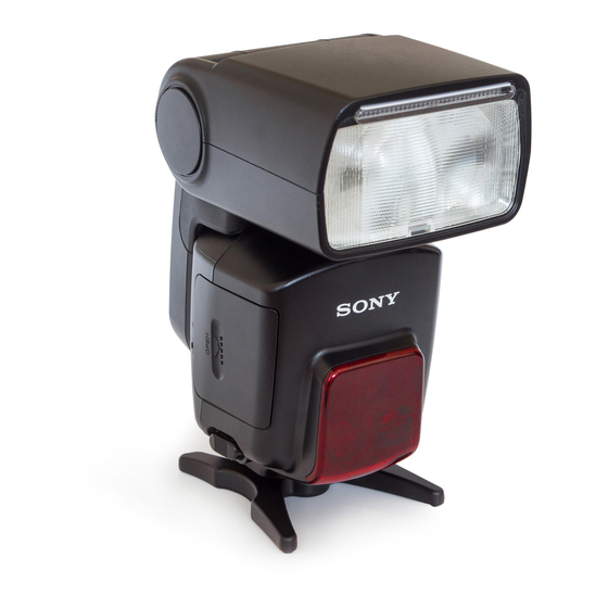
Name of parts A Built-in wide panel (page 34) B Flashtube C Wireless control signal receiver (page 54) D AF illuminator (page 72) Remove the protective sheet from the front of the AF illuminator before use. E Mounting foot (page 18) F Terminal cap (page 69, 71) G Bounce sheet (page 36) - Page 11 H Bounce indicator (upper angle) (page 36) I LCD panel (page 13) J Control panel (page 12) K Bounce indicator (side angle) (page 36) L Mounting-foot release button (page 19) M Battery-chamber door (page 15) N Mini-stand (page 57) * Tripod mount...
-
Page 12: Control Panel
Control panel A TTL/M (MANUAL/MULTI) button (page 44, 48, 61, 66, 73) B MODE button (page 22) C TEST button (page 31) The status while the lamp is lit Amber: Flash ready Green: Proper exposure D Fn (function)/direction buttons (page 44, 48, 61, 64, 66, 74) E POWER switch (page 20) F LCD illuminator button (page 24) -
Page 13: Lcd Panel
LCD panel A Zoom indicator (page 32) B Flash mode indicator (page 22, 61, 64, 66) C Flash-OFF indicator (page 22) D Power-level indicator (page 43, E Zoom/Multiple-flash repetition display (page 32, 48) F mm indicator (page 32) G TIMES indicator (page 48) H Bounce indicator (page 36) I Custom indicator (page 74) J High-speed-sync indicator... - Page 14 Q Wireless controller/remote indicator (page 54) R Flash-range/Multiple-flash frequency/flash-ratio display (page 27, 48, 66) S Ratio-flash indicator (page 66) T Operating indicator (page 78) U Flash-range-warning (near side) indicator (page 27, 43) V TTL indicator (page 43) W Manual-flash indicator (page 43) X Multiple-flash indicator (page 48)
-
Page 15: Preparations
Preparations Inserting batteries The HVL-F58AM may be powered by : • Four AA-size alkaline batteries* • Four AA-size rechargeable nickel-metal hydride (Ni-MH) batteries* * Batteries are not supplied. Always ensure that rechargeable nickel-metal hydride batteries are charged in the specified charger unit. Open the battery-chamber door as shown. -
Page 16: Checking Batteries
Checking Batteries indicator on the data panel blinks when the batteries are low. • If nothing appears on the LCD panel when the POWER switch is set to ON, check the orientation of the batteries. blinking Changing the batteries is recommended. The flash unit can still be used when the TEST button lights up in amber. - Page 17 OVERHEAT indicator When the temperature of this unit rises at the time of continuous flash use or use in a high temperature environment, the flash suspends operation automatically. • The OVERHEAT indicator blinks when overheating is detected. • The flash operation is suspended until the temperature of the unit falls. •...
-
Page 18: Attachment And Removal Of The Flash Unit
Attachment and removal of the flash unit Attaching the flash unit to the camera With the flash unit turned off, push the mounting foot firmly and fully into the accessory shoe of the camera. • The flash unit is locked in place automatically. •... -
Page 19: Removing The Flash Unit From The Camera
Removing the flash unit from the camera While pressing the mounting-foot release button 1, remove the flash unit 2. -
Page 20: Turning On The Power
Turning on the power Set the POWER switch to ON. The power of the flash unit turns on. • When the power of the flash unit is turned on, the LCD panel lights up. To turn the power off Set the POWER switch to OFF. -
Page 21: Power Save Mode
• The flash unit turns into power save mode automatically when the POWER switch of the camera is set to OFF.* * When Sony digital single-lens reflex camera (other than DSLR-A100) is used. • Since your camera does not communicate with the flash unit, the flash mode, the... -
Page 22: Changing The Flash Mode
Changing the flash mode Press the MODE button. • The indicator on the LCD panel changes as follows. When the flash unit is not connected to your camera, or when the camera is in power save mode or the LCD monitor is being turned off when the flash unit is connected to your camera: AUTO) t When your camera is turned on and the flash unit is connected to your camera... - Page 23 About flash mode • (Fill-flash mode) The flash unit always fires. • AUTO (Auto flash mode) The flash unit is set to this mode when the camera is set to auto flash. • WL (Wireless flash mode) This mode is used during wireless flash photography. •...
-
Page 24: Lcd Panel Illuminator
LCD panel illuminator Illuminates the data panel at low-light levels. Press the button. • The LCD panel is illuminated for approximately eight seconds. This period is extended if the flash or camera is used during this time. • Press the button again while the LCD panel is illuminated to extinguish the LCD panel illuminator. -
Page 25: Basics
Basics Program auto flash (The basics) Select the P mode on the camera. Press the MODE button to display [ AUTO] or [ ] on the LCD panel. • [ AUTO] lights up when the camera is set to Autoflash. Only [ ] lights up when the camera is set to Full-flash. - Page 26 Press the shutter button halfway down and make sure that the subject is within the flash range. • See page 27 for details on the flash range. When the flash unit is charged, press the shutter button to take a photo. •...
-
Page 27: Flash Range
When the correct exposure has been obtained for the photo just taken, the TEST button on the control panel blinks in green. • The photo will be under-exposed because of a lack of luminescence if taken before charging is complete. •... - Page 28 The range that can be displayed on the LCD panel is from 1.5 m to 28 m (0.7 m to 28 m for downward bounce; see page 41). When the distance is beyond this range, is lit on either side of the Flash range. •...
-
Page 29: Using Flash In Each Recording Mode Of The Camera
Using flash in each recording mode of the camera This section explains how to use the flash unit in each recording mode of the camera. Aperture priority flash photography Select the A mode on the camera. Press the MODE button to display [ ]. •... - Page 30 Shutter speed priority flash photography (S) Select the S mode on the camera. Press the MODE button to display [ ]. • Fill-flash is selected. Set the shutter speed, and focus the subject. Press the shutter button when charging is complete. Manual exposure mode flash photography (M) Select the M mode on the camera.
-
Page 31: Applications
Applications Test-flash You can try a test flash before shooting. Check the light level using the test flash when you use a flash meter, etc., in the manual flash (M) mode. Press the TEST button when the TEST button lights up in amber. -
Page 32: Zoom Flash Coverage
Auto zoom control optimized for image sensor size By using a Sony digital single lens reflex camera, other than the DSLR-A100, with this flash unit, the flash unit will provide optimal flash coverage according to the image sensor size (APS-C format/35 mm-format) of the camera. - Page 33 Manual zoom You can manually set the flash coverage regardless of the focal length of the lens in use (manual zoom). Press the ZOOM button to select the flash coverage to be set. • The zoom coverage is changed in the following order. 105 mm t 70 mm t 50 mm t 35 mm t 28 mm t 24 mm t A ZOOM t 105 mm t .
- Page 34 Built-in wide panel (16 mm zoom angle) Pulling out the built-in wide panel expands flash coverage to a focal length of 16 Pull out the wide panel and set it at the front of flash tube, and then push back the bounce sheet. •...
- Page 35 Flash coverage & focal length The larger the focal length figure of the lens on a camera, the further away a subject can be photographed to take up the full screen; but the area that can be covered becomes smaller. Conversely, with a smaller focal length figure, subjects can be photographed with wider coverage.
-
Page 36: Bounce Flash
Bounce flash Using the flash unit with a wall directly behind the subject produces strong shadows on the wall. By directing the flash unit at the ceiling you can illuminate the subject with reflected light, reducing the intensity of the shadows and producing a softer light on the screen. - Page 37 Rotate the flash unit upwards or to the left and right while holding the camera firmly. • appears on the LCD panel. The flash may be set to the following angles. • Upwards: 45°, 60°, 75°, 90°, 120°, 150° • Downwards: 10° (see “Close-up photography (downward bounce)” page 41) •...
- Page 38 • When the flash is rotated upwards, the flash range is not displayed on the LCD panel. High-speed sync (page 47) is also cleared. • When the flash is rotated upwards, the bounce indicator does not appear. • Use a white ceiling or wall to reflect the flash. A colored surface may color the light.
- Page 39 When the flash is bounced upwards Determine the angle in relation to the following table. Focal length of lens 70 mm minimum 28 - 70 mm 28 mm maximum Using the bounce sheet The bounce sheet creates a highlight in the subject's eyes and makes the subject look more vibrant.
- Page 40 90° sideways bounce When the bounce angle is set to portrait position, the top and bottom of the photo may darken. In this case, use the built-in wide panel or set the bounce angle to • blinks on the LCD panel. •...
-
Page 41: Close-Up Photography (Downward Bounce)
Close-up photography (downward bounce) Tilt the flash slightly downwards when photographing objects between 0.7 m and 1.5 m from the camera to ensure accurate illumination. Rotate the flash downwards with holding the camera firmly. • The rotation angle is 10°. - Page 42 Use an off-camera flash, Macro Twin Flash, or Ring Light. • The downward bounce can be used only when the bounce angle is set to 0° or 90°...
-
Page 43: Manual Flash (M)
Manual flash (M) Normal TTL flash metering automatically adjusts the flash intensity to provide the proper exposure for the subject. Manual flash provides a fixed flash intensity irrespective of the brightness of the subject and the camera setting. • Manual flash can only be used when the camera is in the M mode. In other modes, TTL measuring is selected automatically. - Page 44 Press the TTL/M button to display panel. • The modes change in the following order. Press the g or G button to select the power level to be set. • The power level is changed in following order. 1/1 t 1/2 t 1/4 t 1/8 t 1/16 t 1/32 on the LCD...
- Page 45 • When the shutter button is pressed halfway down, the distance at which the proper exposure is obtained appears on the LCD panel. • In manual flash photography, if the power level is set at 1/1 then the flash will go off at full power.
- Page 46 TTL flash Manual flash provides a fixed flash intensity irrespective of the brightness of the subject and the camera setting. TTL* flash measures the light from the subject that is reflected through the lens. TTL metering also has a P-TTL metering function, which adds a pre-flash to TTL metering, and an ADI metering function, which adds distance data to the P-TTL metering.
-
Page 47: High-Speed Sync (Hss)
High-speed sync (HSS) High-speed sync High-speed sync eliminates the restrictions of flash sync speed and enables the flash to be used through the entire shutter speed range of the camera. The increased selectable aperture range allows flash photography with a wide aperture, leaving the background out of focus and accentuating the front subject. -
Page 48: Multiple Flash (Multi)
Multiple flash (MULTI) The flash is triggered a number of times while the shutter is open (multiple flash). Multiple flash allows motion of the subject to be captured in a photograph for later analysis. • The camera must be set to the M mode for multiple flash photography. Set the camera to the M mode. - Page 49 Press the Fn button to make [TIMES] blink. • The current number of flashes for multiple flash is displayed on the LCD panel.
- Page 50 Press the f or F button to select the number of flashes. • The number of flashes may be selected from the following. - -, 100, 90, 80, 70, 60, 50, 45, 40, 35, 30, 25, 20, 15, 10, 9, 8, 7, 6, 5, 4, 3, 2 •...
- Page 51 Press the f or F button to select the flash frequency. • The flash frequency may be selected from the following. 100, 90, 80, 70, 60, 50, 40, 30, 20, 10, 9, 8, 7, 6, 5, 4, 3, 2, 1 •...
- Page 52 Press the Fn button. Set the shutter speed and aperture. • The shutter speed is calculated as follows to suit the selected flash frequency and number of flashes. Number of flashes (TIME) ÷ Flash frequency (Hz) = Shutter speed For example, when ten flashes and 5 Hz are selected, 10 ÷ 5 = 2 requires a shutter speed of longer than two seconds.
- Page 53 Maximum number of continuous flashes The maximum number of continuous flashes during multiple flash photography is limited by the charge in the battery. Use the following values as a guide. With alkaline batteries Power level 100 90 80 70 60 50 40 30 20 10 1/16 1/32 14 14 14 14 14 18 18 20 20 25 35 35 40 50 50 50 50 100 100*...
-
Page 54: Wireless Flash Mode (Wl)
Wireless flash mode (WL) Photographs taken with the flash unit attached to the camera are flat as shown in photo 1. In such cases, remove the flash unit from the camera and position it to obtain a more three-dimensional effect as shown in photo 2. And by using 2 or more flash units, you can create more detailed light conditions as shown in photo When taking this type of photograph with a single lens reflex camera, the camera and the flash unit are most commonly connected by a cable. -
Page 55: Wireless Flash Range
Wireless Flash Range The wireless flash uses a light signal from the flash as a trigger to operate the off- camera flash unit. Follow the points below when positioning the camera, flash, and subject. • Photograph in dark locations indoors. -
Page 56: Notes On Wireless Flash
Distance camera-HVL-F58AM-subject Distance camera-subject (Table 1) Shutter speed All shutter speeds Aperture 1.4 - 5 1 - 5 1 - 5 • The distances in the above table assume the use of ISO 100. If ISO 400 is used the distances must be multiplied by a factor of two (assume a limit of 5 m). •... - Page 57 Opening and closing the mini-stand • The mini-stand is collapsible and must be open when used. Attaching and removing the mini- stand • Use the supplied mini-stand when the flash unit is separate from the camera. Attachment • You can attach the flash unit to a tripod using the tripod socket holes in the mini- stand.
- Page 58 You can take a photo with wireless flash while controlling the lighting ratio of some groups of flash units by using this flash unit as a controller. (1) When using HVL-F58AM/HVL-F42AM as off-camera flash, you can control the lighting ratio up to 3 groups ([CTRL], [RMT], [RMT2]). You can use this function with DSLR-A900/A700.
- Page 59 • For details, see “Combination of camera, off-camera flash and controller.” • You can use several off-camera flashes at the same time. • The off-camera flash fires with the power level set in each flash when the off- camera flash is in the MANUAL mode.
- Page 60 When using DSLR-A700, this flash unit cannot be set to [CTRL](CTRL2). If the flash unit is already set to [CTRL], the setting is canceled automatically. For other cameras, see the operating instructions supplied with each camera. HVL-F42AM used as off-camera flash is included in the [RMT] group.
- Page 61 [1] Wireless flash photography with built-in flash of the camera Use only an off-camera flash unit, using the light from the built-in flash as a signal. Built-in flash Attach the flash unit to the camera and turn the power of the flash unit and camera on.
- Page 62 Make sure that the built-in flash and flash unit are fully charged. • “ ” is lit in the viewfinder when the built-in flash is fully charged. • When the flash unit is fully charged in the wireless flash mode, the AF illuminator on the front blinks, and the TEST button is lit in amber.
- Page 63 Press the g or G button to make [RMT] or [RMT2] blink. Press the Fn button. • Make sure that the wireless channel of the off-camera flash is set to the same channel as the controller. For details on setting the wireless channel, see “Custom setting”...
- Page 64 You can take a photo with wireless flash by using 2 flash units, one as a controller and the other as an off-camera flash unit, even if the camera does not have a built-in flash.
- Page 65 • If the test-flash does not work, change the position of the camera, flash, and subject, or point the wireless control-signal receiver towards the camera. Moreover, make sure that wireless channel of the off-camera flash is set to the same channel as the controller.
- Page 66 [RMT]. For [RMT2], only HVL-F58AM that is set to [CTRL1] can be used in a group. • When using HVL-F56AM/HVL-F36AM as off-camera flash, set the controller mode to [CTRL2]. In [CTRL2] mode, you can control the lighting ratio of only 2 groups. For details on setting the controller mode, see [C03] in “Custom setting”...
- Page 67 • Set the power level ratio to [--] on the flash unit when there is an off- camera flash (RMT/RMT2) you don't want to fire when you use the flash unit with the controller after setting the flash unit to [CTRL1].
- Page 68 • If the test-flash does not work, change the position of the camera, flash and subject, or point the wireless control-signal receiver towards the camera. Moreover, make sure that the wireless channel of the off-camera flash is set to the same channel as the controller.
-
Page 69: Connecting Camera And Flash By Cable
Connecting camera and flash by cable Using the off-camera cables FA-CC1AM (optional) allows photography with flash units separate from the camera. Up to four flash units can be connected together. Being able to take photographs without having to consider the positioning of the flash unit provides considerable freedom to create a variety of shadow effects on the subject. - Page 70 • In this mode, ADI metering will be canceled and Pre-flash TTL metering will be used automatically (page 43). • High-speed sync in the P mode cannot be used when the flash is connected with the off-camera cable FA-CC1AM (optional). •...
-
Page 71: Using External Battery Adaptor
Using external battery adaptor You can use an External Battery Adaptor FA-EB1AM (optional) as an external power supply. Remove the terminal cap. Insert the plug of connection cable into the external power terminal. • Use an external battery adaptor or cable for this flash unit for the external power terminal or accessory terminals. -
Page 72: Af Illuminator
AF illuminator In low-light or when subject contrast is low, when the shutter button is pressed halfway down for Auto Focus, the red lamp on the front of the flash unit will light. This is the AF illuminator used as an aid in Auto Focus. •... -
Page 73: Reset To The Default Settings
Reset to the default settings Press the MODE and TTL/M buttons together for three seconds. Most flash functions return to their default settings. Item Flash on/off Flash coverage (zoom) Flash mode (TTL/M/MULTI) Wireless flash (WL) Lighting ratio Power level in TTL/M (LEVEL) Power level in multiple flash (LEVEL) Frequency in multiple flash (Hz) Repetition in multiple flash (TIMES) -
Page 74: Custom Setting
Custom setting The various flash settings may be changed as necessary. The following eight items may be changed. • HSS setting (on/off) • Wireless channel setting (channels 1 to 4) • Wireless controller mode setting (1/2) • Recording mode in which manual flash or multiple-flash may be set (M mode only/all modes) •... - Page 75 Press the g or G button to select the item. For details on the each setting, refer to “Changing the custom setting” (page 78). Press the Fn button to finish the custom setting. • The LCD panel returns to the original display. •...
- Page 76 C01. HSS setting C02. Wireless channel setting Channel 1 C03. Wireless controller mode setting Control 1 C04. Recording mode in which manual flash or multiple-flash may be set M mode only Select with the f button or F button Channel 2 Control 2 All modes Channel 3...
- Page 77 Select with the f button or F button C05. Test-flash setting Once 3 times 4 seconds C06. Time to power save 30 seconds 3 minutes 30 minutes none C07. Time to power save when using wireless flash 60 minutes none C08.
- Page 78 Changing the custom setting This is an explanation of how to change each custom setting is given below. To set the high-speed sync (C01) You can set the high-speed sync. Press the f or F button to select [ON]. • The display switches between [ON] and [OFF]. •...
- Page 79 [CTRL1] and [CTRL2]. The wireless controller indicator on the LCD panel is displayed as follows. [CTRL1] mode: [CTRL+] When using HVL-F58AM/HVL-F42AM as off-camera flash, select this mode. [CTRL2] mode: [CTRL] When using HVL-F56AM/HVL-F36AM as off-camera flash, select this mode.
- Page 80 To change the test-flash mode (C05) You can change the flashing method when using test-flash. Press the f or F button to select the test-flash setting. • The display is changed in the following order. [TEST1] y [TEST3] y [TESTM] y . . . [TEST1] : flashes once at the set light level.
-
Page 81: Notes On Use
Additional Information Notes on use While shooting • This flash unit generates strong light, so it should not be used directly in front of the eyes. • Do not use the flash 20 times in a row or in quick succession in order to prevent heating and degradation of the camera and flash unit. - Page 82 • Remove the batteries only after turning the power off and waiting several minutes, when changing the batteries. The batteries may be hot, depending on the battery type. Remove them carefully. • Remove and store the batteries when you do not intend to use the camera for a long time.
-
Page 83: Maintenance
Maintenance Remove this unit from the camera. Clean the flash with a dry soft cloth. If the flash has been in contact with sand, wiping will damage the surface, and it should therefore be cleaned gently using a blower. In the event of stubborn stains, use a cloth lightly dampened with a mild detergent solution, and then wipe the unit clean with a dry soft cloth. -
Page 84: Specifications
Specifications Guide number Normal flash (ISO100) Manual flash/35mm-format Power level 1/16 1/32 * When the wide panel is attached. APS-C format Power level 1/16 1/32 * When the wide panel is attached. Flash coverage setting (mm) 11.9 20.8 21.8 25.1 14.7 15.4 17.8... - Page 85 HSS flat flash (ISO100) Manual flash/35mm-format Shutter speed 1/250 1/500 1/1000 1/2000 1/4000 1/8000 1/12000 * When the wide panel is attached. APS-C format Shutter speed 1/250 1/500 1/1000 1/2000 1/4000 1/8000 1/12000 * When the wide panel is attached. Frequency/Repetition Frequency (sec) Repetition (times)
- Page 86 Functions in these operating instructions depend on testing conditions at our firm. Design and specifications are subject to change without notice. Trademark is a trademark of Sony Corporation. Central area: 0.5 m to 10 m Peripheral areas : 0.5 m to 3 m...
- Page 88 Printed on 70% or more recycled paper using VOC (Volatile Organic Compound)-free vegetable oil based ink. Printed in Japan...