Table of Contents
Advertisement
Advertisement
Table of Contents

Related Manuals for AB Regin Corrigo E81D-3

Summary of Contents for AB Regin Corrigo E81D-3
- Page 1 Corrigo manual Ventilation application © Copyright AB Regin, Sweden, 2013...
- Page 2 No part of this document may be reproduced or transmitted in any form, in any fashion, electronically or mechanically, without the express, written permission of Regin. COPYRIGHT AB Regin. All rights reserved. TRADEMARKS ©...
-
Page 3: Table Of Contents
Table of contents CHAPTER 1 ABOUT THE MANUAL ....................6 More information ........................6 CHAPTER 2 ABOUT CORRIGO ......................7 2.1 News in version 3.3 ........................ 7 2.2 Application choice ......................... 7 2.3 Technical data ........................12 CHAPTER 3 INSTALLATION AND WIRING ..................14 3.1 Installation ........................... - Page 4 13.4 Extended running ......................67 13.5 Timer outputs 1…5 ......................67 13.6 Holidays ..........................68 CHAPTER 14 MANUAL / AUTO ..................... 69 CHAPTER 15 SETTINGS ......................... 72 15.1 Control temp ........................72 15.2 Control pressure ........................ 73 15.3 Control flow ........................73 15.4 Humidity control ........................
- Page 5 INDEX ............................110 APPENDIX FREQUENCY CONVERTERS ..................114...
-
Page 6: Chapter 1 About The Manual
Chapter 1 About the manual This manual covers all the models in the Corrigo series used with the ventilation application. This revision covers program revisions from 3.3. More information More information about Corrigo can be found in: • Corrigo ventilation user guide – A simplified manual •... -
Page 7: Chapter 2 About Corrigo
Chapter 2 About Corrigo The Corrigo series comprises three model sizes: 8, 15 or 28 in-/outputs. In each third generation model Corrigo, all applications are loaded in a separate memory area. The models have article number E...-3 (where 3 stands for third generation). A new feature in version 3.3 are models with three communication ports. - Page 8 Use the up and down arrows to move the cursor in the left edge of the display to the function you wish to select. Select “Application” and press the right arrow. Corrigo Vent.131021 Expansion unit 1 Expansion unit 2 Corrigo Vent.140212 Move the cursor to the desired application.
- Page 9 Input/Output: Enables In-/Output reading and writing. 2.2.2 Ventilation application The temperature controller is based on a supply air PI-controller for heating control with a pre- programmed set of control modes. A number of different control functions as well as analogue and digital in- and output functions can be bound to this controller.
- Page 10 Demand controlled ventilation In buildings with strongly varying occupancy the fan speeds or mixing dampers can be controlled by the air quality measured by a CO sensor. Support control When using the control function room control or extract air temperature control, it is possible to utilise support-heating and/or support-cooling.
- Page 11 Corrigo hardware overview RS485 • • • • • • • • • • • • • • BACnet/IP • • • • • • • • • • • • TCP/IP • • • • • • • • •...
-
Page 12: Technical Data
2.3 Technical data Protection class ........................IP20 Display............4 rows of 20 characters. Background illumination. LEDs Yellow ....................... Settable parameter Red ....................... Alarm indication Clock ..............Year base 24 hour clock with battery backup. Automatic summer-/winter-time changeover. Operating system ......................EXOreal Supply voltage ............ - Page 13 Inputs Analogue inputs AI ..........Settable 0…10 V DC or PT1000, 12 bit A/D Digital inputs DI ..................Potential-free closure Universal inputs UI ........... Can be set to act as either an analogue input or a digital input with specifications as above Outputs Analogue outputs AO ..........
-
Page 14: Chapter 3 Installation And Wiring
Chapter 3 Installation and wiring 3.1 Installation Corrigo can be mounted in a DIN-standard casing (minimum 9 modules), on a DIN-rail in a cabinet or, using a suitable front-mounting kit, in a cabinet door or other control panel. Ambient temperature: 0…50°C. Humidity: Max. - Page 15 3.2.1 Supply voltage 24 V AC ±15%, 50…60 Hz or 21…36 V DC If Corrigo and its connected actuators share the same transformer, it is essential that the same transformer pole is used as reference for all the equipment. The equipment may otherwise not function as intended and may also suffer damages.
- Page 16 A number of different wiring alternatives are possible depending on the type of supply voltage to the Corrigo and the relay type. 24 V AC supply and 24 V AC relays 24 VAC 24 V AC 24 V DC supply and 24 V DC relays 24 V DC 24 V AC supply and 24 V DC relays 24 V AC...
- Page 17 24 V DC supply and 24 V AC relays 24 V DC 3.2.3 Input and output lists The lists below are intended to be used during commissioning to help you keep track of the desired input and output functions. The left column contains a description of the in-/output signal, the middle column displays the name ©...
- Page 18 © Description E tool Display Intake temperature Intake Temp Intaketemp Extra temperature sensor 1 Extra Sensor Temp 1 Extrasensor Extra temperature sensor 2 Extra Sensor Temp 2 Extrasensor 2 Extra temperature sensor 3 Extra Sensor Temp 3 Extrasensor 3 Extra temperature sensor 4 Extra Sensor Temp 4 Extrasensor 4...
- Page 19 Analogue output signal © Description E tool Display Inactive output Not used Not used Y1 Actuator Heating Heating Y1 Y1-Heating Y2 Actuator Exchanger Exchanger Y2 Y2-Exchanger Y3 Actuator Cooling Cooling Y3 Y3-Cooling Frequency converter, supply air fan Frequency converter, extract air fan Actuator Humidity control Dehumidification/ Humidity...
- Page 20 © Description E tool Display Recirculation damper Recirculation Air Damper Recirc. damper Heating 3-position actuator, increase Heating Increase Heat-inc Heating 3-position actuator, decrease Heating Decrease Heat-dec Exchanger 3-position actuator, increase Exchanger Increase Exch-inc Exchanger 3-position actuator, decrease Exchanger Decrease Exch-dec Cooling 3-position actuator, increase Cooling Increase...
-
Page 21: Chapter 4 Commissioning
Chapter 4 Commissioning General Before the Corrigo can be used, all inputs and outputs must first be configured, as well as all relevant parameters. All commissioning can be done using the Corrigo front panel display and buttons or using the external display unit E3-DSP. - Page 22 Option 2: Read this manual in the order given below: The manual has been designed to act as a guide through the commissioning. The last chapters of the manual, not listed below, cover menus and functions that are not used during commissioning. Functional description Start by reading chapter 5.
- Page 23 Manual/Auto Chapter 14 Learn to use manual control. Very useful for testing out your system. Other functions Chapter 18 Alarm handling etc. Manual Corrigo Ventilation, revision R Chapter 4 Commissioning...
-
Page 24: Chapter 5 Functional Description
Chapter 5 Functional description 5.1 Temperature control General Corrigo has a choice of the following control modes: Supply air control Outdoor temperature compensated supply air control Cascaded room temperature control Cascade connected extract air temperature control Outdoor temperature dependent switching between supply air control with outdoor temperature compensation and room temperature control Outdoor temperature dependent switching between supply air control with outdoor temperature compensation and extract air control... - Page 25 Example: 0 % Cooling at HCOut = 30 % 100 % Cooling at HCOut = 0 % 0 % heat exch. at HCOut = 32 % 100 % heat exch. at HCOut = 50 % 0 % Heating at HCOut = 54 % 100 % Heating at HCOut = 100 % Output signal 100%...
- Page 26 5.1.1 Control modes 1. Supply air control The supply air temperature is kept at the setpoint value by controlling the output signals for "Heating Y1", "Exchanger Y2", "Cooling Y3", "Extra sequence Y4" and “Extra sequence Y5”. A single PI control loop is used. The setpoint value is set using the front panel or alternatively using an external setpoint device.
- Page 27 7. Outdoor compensated room temperature control The room temperature can be compensated when the outdoor temperature increases. One can, for instance, imagine accepting a slightly higher room temperature if it is warm outside or, conversely, a slightly lower temperature if it is chilly. This function is included to conserve energy. 8.
- Page 28 The internal signal (“Internal signal”) will begin to rise as the frost protection temperature falls below “Alarm level” + “Prop. Band” in order to reach 100 % output when the signal has fallen to “Alarm level”. When ”Internal signal” reaches 100 % or the digital input ”Deicing Heat exchanger” is activated, the unit is shut down, the heating output is set to completely open mode and an alarm is activated.
- Page 29 5.1.2.3 Water heating and electric heating The water heating is controlled by "Y1 Heating", and the electric heating is controlled by the sequence "Split". Split (see the section Split of optional temp sequence) must always be set to "Heating". On increasing heat demand, the water heating is first activated and then, if needed, the electric heating.
- Page 30 A PI-controller compares the de-icing setpoint with the signal ”De-icing Exchanger”. The lesser of the output signal from this controller and the output from the ordinary controller is used as output to the dampers. Rotating exchanger Control Rotational speed is controlled by the analogue signal ”Y2 Heat exchanger” or by two digital outputs “Exchanger 3-pos.
- Page 31 Minimum limit An outdoor air minimum limit for can be set using the front panel. The limit value is settable between 0 and 100 %. In- and outputs Plate Rotating Liquid Dampers Exch. Outdoor temp. sensor (optional, outd. temp start) Activate exchanger (optional, outd.
- Page 32 Y1 = 1 Step controllers and Change-over The digital output signals "Heating/cooling step 1", "Heating/cooling step 2" and "Heating/cooling step 3" are used for step controllers during Change-over control (see section 5.1.12). They have the same functions as other step controller outputs, but are set to either heating or cooling depending on whether heating or cooling is required.
- Page 33 When two DX cooling steps are used with binary function, the cooling effect is divided into three steps. The desired blocking level can be set individually for each of these steps. When three DX cooling steps are used with binary function, the cooling effect is divided into seven steps.
- Page 34 Support control heating Demand for support control heating is when the room temperature is lower than the start value which is settable 0 to 30°C. The fans will run at the preset speed, the heater and the heat exchanger are controlled by the supply air temperature controller with the configured max limitation for the supply air (FS=30°C) as setpoint and the cooling is shut off (0%).
- Page 35 In- and outputs Outdoor temperature sensor or Intake temperature Room sensor or Extract air sensor Free cooling operation 5.1.7 Cooling recovery If the cooling recovery has been configured, there is a cooling requirement and the extract air temperature is a settable amount lower than the outdoor temperature, cooling recovery can be activated.
- Page 36 5.1.9 Heat exchanger efficiency monitoring General The function calculates the heat exchanger temperature efficiency in percent when the output signal to the exchanger is higher than 5 % and the outdoor temperature is lower than 10°C. When the control signal is lower than 5 % or the outdoor temperature is higher than 10°C the display will show 0 %.
-
Page 37: Extra Control Circuit
To lower the temperature, it is possible to configure free cooling to be used during recirculation, if the conditions for free cooling are fulfilled. Then, the recirculation damper closes, the supply and extract air dampers open and the extract air fan starts (the supply air fan also starts, if it is not already running). -
Page 38: Humidity Control
5.3 Humidity control General Humidity control can be configured as Humidification, Dehumidification or both Humidification and Dehumidification. Two humidity sensors can be connected, a room sensor for control and an optional duct sensor for maximum limiting. The limit sensor can be omitted. The humidity control is handled by a PI-controller. -
Page 39: Fan Control
5.4 Fan control General Fans can be 1-speed, 2-speed or variable speed via a frequency converter. 1-speed fans are controlled using the digital outputs "Start SAF-Normal" and "Start EAF-Normal". 2-speed fans are controlled using the digital outputs "Start SAF-Normal" and "Start EAF-Normal" as well as "Start SAF-reduced"... - Page 40 Outdoor compensation When running pressure control, it is also possible to outdoor compensate the pressure setpoint value. The outdoor compensation is linear and is set using two parameter pairs which give the value of the compensation at two different outdoor temperatures. The compensation can be positive or negative. The outdoor compensation is set in the menu Actual/Setpoint.
- Page 41 Outdoor compensation Also when running flow control, it is possible to outdoor compensate the setpoint value. The outdoor compensation is linear and is set using two parameter pairs which give the value of the compensation at two different outdoor temperatures. The compensation can be positive or negative. The outdoor compensation is set using the menu Air control>Pressure contr.
- Page 42 Frequency control SAF with EAF slave The rotational speed of the supply air fan is controlled by a pressure transmitter which is placed in the supply air duct. The extract air fan does not have a pressure transmitter, instead you let the output for the extract air fan follow the control signal for the supply air fan.
- Page 43 1-speed 2-speed Pressure/ Flow Start SAF Normal Start EAF Normal Start SAF reduced Start EAF reduced SAF frequency start EAF frequency start Indication/alarm SAF Indication/alarm EAF Pressure transmitter SAF Pressure transmitter EAF Pressure transmitter 2 SAF Extra pressure transmitter SAF Extra EAF Pressure External flow setpoint Frequency converter SAF...
- Page 44 When used with 2-speed fans they will start using reduced speed when the CO value rises above control value one and switch to normal speed when the CO value reaches control value two. The fans will stop when the CO value falls 160 ppm below control value one.
-
Page 45: Pump Control
5.5 Pump control Digital inputs and outputs can be configured for pump control. All the pumps can use run indication with malfunction alarm or an alarm input connected to a motor protection or similar. 5.5.1 Heating circuit The circulation pump for the heating circuit will always run when the outdoor temperature is lower than a settable value (FS +10°C). -
Page 46: Extended Running And External Switch
5.6.2 Fire dampers Fire dampers are normally configured to open on fire alarm. However, they can be configured to be normally open instead via the display. Se chapter 16.15 for more information on the function. Fire damper exercising Fire damper exercising can be configured. The exercise interval is settable. To be able to use this function, all the dampers must have end-position switches. -
Page 47: Time-Switch Outputs
In- and outputs Extended Operation, Normal Extended Operation, Reduced External switch 5.8 Time-switch outputs Up to five digital time-switch outputs can be configured. Each timer channel has a separate scheduler with two periods per week-day. Timer output five can be used to control the function Recirculation. See 5.1.11. In- and outputs Extra time channel 1 Extra time channel 2... - Page 48 Alarm text The alarm text that should be shown in the display when there is an alarm can be changed using E © © tool . For more information, see the E tool manual. In- and outputs Sum alarm A + B Sum alarm A Sum alarm B/C Chapter 5 Functional description...
-
Page 49: Chapter 6 Starting And Stopping The Unit
Chapter 6 Starting and stopping the unit 6.1 Start conditions The unit will be started and will run when any one of the following conditions is met: Timer output for normal speed or timer output for reduced speed is ON The unit is started manually using the Corrigo front panel or via E3-DSP Digital input for extended running is activated Support control is activated and the present room temperature is higher/lower than the... -
Page 50: Start Sequence
6.3 Start sequence Start of the unit will run according to the following sequence: If the controller is configured for water heating and has an outdoor temperature sensor and the outdoor temperature is below +3ºC the heating valve is opened and the heating circulation pump is started. -
Page 51: Chapter 7 Display, Leds And Buttons
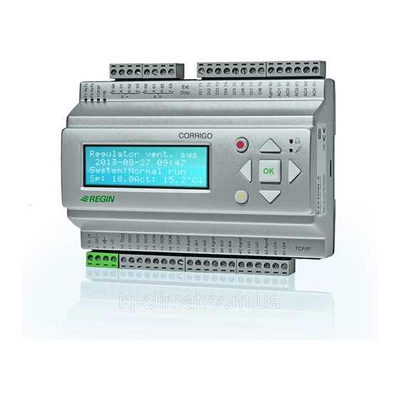
Chapter 7 Display, LEDs and buttons This section is applicable to Corrigo units with display and buttons but also to the hand terminal E3- DSP which can be connected to Corrigo units without display and buttons. Room units are available with or without display, or as a touch display (see instructions and product sheets for ED-RU..., ED-RU-D... - Page 52 Regulator vent. sys 2008-11-20 13:30 System: Running Sp: 18.0 Act: 18.2°C Pressing DOWN will move you through the menu choices at this, the lowest level. UP will move you back through the choices. Which menus are shown depends on which access level you are using (see chapter eight for more information about logging on to higher levels).
-
Page 53: Chapter 8 Access Rights
Chapter 8 Access rights There are four different access levels. The Admin level has the highest access, while the Service, Operator and basic “no-log on” level have the lowest. The choice of access level determines which menus are shown, as well as which parameters can be changed in the displayed menus. Admin level gives full read/write access to all settings and parameters in all menus. -
Page 54: Change Password
8.3 Change password As default Corrigo comes with the following passwords for the different levels: Admin 1111 Service 2222 Operator 3333 Normal 5555 You can only change the password for log on levels lower or equal to the presently active level, i.e. if you are logged in as Admin you can change all passwords, but as Operator you can only change the Operator and Normal passwords. -
Page 55: Chapter 9 Running Mode
Chapter 9 Running mode Collected here are a number of menus showing running mode, selected functions, alarm events and status of inputs and outputs. Running mode Selected functions Alarm events Input/Output 9.1 Running mode, unit The unit’s running mode can be changed without logging on. Running mode Auto Running time... -
Page 56: Alarm Events
Frost protection Active Cooling recovery External setpoint Not active 9.3 Alarm events Alarm log which contains the 40 latest alarm events. The most recent event is listed first. The alarm log can only be used for viewing the alarm history. Alarms are handled in a special area, see section 18.1. -
Page 57: Chapter 10 Temperature
Chapter 10 Temperature Here you can view all actual and setpoint values for temperature control. The menu is visible to all users, regardless of log on level. However, to make changes you need at least Operator authority. The below menus are available, providing the corresponding input has been activated. Setpoints are available with a separate value for reduced speed. - Page 58 Outdoor comp. setp. 10.0°C = 18.0°C 15.0°C = 18.0°C In-between-values are calculated using straight lines between breakpoints. Setpoints for temperatures lower than the lowest breakpoint and higher than the highest breakpoint are calculated by extending the line between the two last breakpoints at either end. Example: At the lower end the setpoint is increasing by 1°C for every 5 °C lowering of the outdoor temperature.
- Page 59 Outdoor comp. setp. -5.0°C = 23.0°C 0.0°C = 22.0°C 5.0°C = 20.0°C Outdoor comp. setp. 10.0°C = 18.0°C 15.0°C = 18.0°C If cascade control max/min supply setp. Max: 30.0°C Min: 12.0°C In control mode seven, the room setpoint is compensated based on outdoor temperature. Note that the curve must be reset for optimum functionality.
- Page 60 Support control cooling Support cooling Room temp for Start: 30.0°C Stop: 28.0°C Frost protection temperature Frost protection Actual: 30.9°C De-icing exchanger De-icing exchanger Actual: 11.2°C Setpoint: -3.0°C Hysteresis: 1.0°C Heat exchanger efficiency monitoring Efficiency exch. Actual: 93% Output exchanger Actual: 100% Recirculation (see 5.1.11) Temp.setpoint when recirc.
- Page 61 Submenus Outdoortemp Act.: 12.8 °C Humidity Outdoor Act.: 98.7% RH Indoortemp Act.: 17.2 °C Humidity indoor Act.: 55.7 % RH Status enthalpy control Override cool Recovery due to Enthalpy: Active Manual Corrigo Ventilation, revision R Chapter 10 Temperature...
-
Page 62: Chapter 11 Air Control
Chapter 11 Air control Pressure control SAF and EAF When using pressure or flow controlled fans, the setpoint can be temperature compensated. The compensation has the default value 0 Pa, i.e. no compensation is added. The compensation is linear between the setting points. The compensation can be positive or negative. ©... - Page 63 Submenu “Compensation only when” Compensation only when: 1/1-speed: No defrosting: No Flow units can be measured in both m /h (cubic meters per hour) and in CFM (cubic feet per minute). Flow control SAF (there are corresponding menus for EAF) Flow control SAF Actual: 1800 m3/h ...
- Page 64 Flow units can be measured in both m /h (cubic meters per hour) and in CFM (cubic feet per minute). Manual frequency control SAF (there are corresponding menus for EAF) Frequency control manual SAF Output: 75% Submenu "Setpoint" Frequency control manual SAF Output 1/1: 75% Output 1/2: 50%...
-
Page 65: Chapter 12 Humidity Control
Chapter 12 Humidity control Humidity control can be configured as Humidification, Dehumidification or both Humidification and Dehumidification. Two humidity sensors can be connected, a room sensor for control and an optional duct sensor for maximum limiting. The limit sensor can be omitted. The humidity control is handled by a PI-controller. -
Page 66: Chapter 13 Time Settings
Chapter 13 Time settings General Corrigo has a year-base clock function. This means that a week-schedule with holiday periods for a full year can be set. The clock has an automatic summertime/wintertime change-over. Individual schedules for each week-day plus a separate holiday setting. Up to 24 individual holiday periods can be configured. -
Page 67: Timer Reduced Speed
If you want to run the unit from one day to another, e.g. from Mon 22:00 to Tue 09:00, the desired running time for both days must be entered. Normal speed Monday Per 1: 07:00 – 16:00 Per.2: 22:00 - 24:00 Normal speed Tuesday Per 1: 00:00 –... -
Page 68: Holidays
13.6 Holidays Up to 24 separate holiday periods for a full year can be set. A holiday period can be any number of consecutive days from 1…365. The dates are in the format: MM:DD. When the present date falls within a holiday period, the scheduler will use the settings for the weekday “Holiday”. -
Page 69: Chapter 14 Manual / Auto
Chapter 14 Manual / Auto General In this menu the running mode of all the configured output signals and a number of control functions can be manually controlled. This is a very handy feature which simplifies the checking of individual functions in the Corrigo. The running mode for the whole unit is set in the menu "Running mode". - Page 70 EAF: Auto Manual set: 0.0 Y1 heating output Heating Auto Manual set: 0.0 Y2 heat exchanger Exchanger Auto Manual set: 0.0 Y3 cooling Cooling Auto Manual set: 0.0 Humidification/dehumidification Humidification/Dehumidi fication Auto Manual set: 0% Circulation pumps: Heating, Exchanger and Cooling P1-Heating Auto P1-Exchanger...
- Page 71 Extra sequence Y4 Extra sequence Y4 Auto Manual set: 0.0 Extra sequence Y5 Extra sequence Y5 Auto Manual set: 0.0 Manual Corrigo Ventilation, revision R Chapter 14 Manual / Auto...
-
Page 72: Chapter 15 Settings
Chapter 15 Settings In this menu group all settings for all activated functions should be available. The menu group is only available when logging on as Admin. Depending on what choices have been made during configuration, some of the alternatives in this menu group may not be shown. Settings Control temp Control pressure... -
Page 73: Control Pressure
Shutdown mode Shutdown mode P-band: 100.0 °C I-time: 100 Frost protection temperature Frost protection temperature Frost protection Active Setp shutdown: 25°C P-band active: 5°C Fast stop at frost-protection alarm "Setp shutdown" is the shutdown mode setpoint. P-band active 5°C means that the frost protection controller will start overriding the heating output when the frost protection temperature is less than five degrees above the set frost alarm limit. -
Page 74: Humidity Control
Flow control EAF Flow control EAF P-band: 1000 m3/h I-time: 60 sec Min Output: 0 15.4 Humidity control Control humidity P-band: 100.0 %RH I-time: 300.0 15.5 Control Extra unit Control extra unit P-band: 33.0 °C I-time: 100.0 15.6 Alarm settings Alarm settings ... - Page 75 Alarm limit, pressure Control dev SAF 40.0 Pa Control dev EAF 40.0 Pa Alarm limit Humidity Control deviation humidity 10 % Alarm limit, exchanger efficiency Low efficiency 50.0 % Service alarm filter Service alarm (Filter alarm) Time until alarm Activates: 0 month 15.6.2 Alarm delays Alarm delay, supply air Al.
-
Page 76: Save And Restore Settings
Alarm delay, exchanger efficiency Low efficiency 30 min Alarm delay, fan malfunction Alarm delay malfunc. SAF: 120 sec EAF: 120 sec Alarm delay, pump malfunction Alarm delay malfunc. P1-Heating: 5 sec P1-Cooling: 5 sec P1-Exchan.: 20 sec Alarm delay, misc. Alarm delay Filter mon.: 180 sec... -
Page 77: Chapter 16 Expansion Model
Chapter 16 Expansion model 2 and 3 port Corrigo units are available with or without display. Both models have a TCP/IP port and one or two serial ports. For a list of the various models, see the Corrigo model overview in chapter 2. - Page 78 16.2.2 Expansion units EXOline Communication between the master and expansion units takes place via EXOline. The slave controllers will be given the addresses 241:1 and 241:2 (ELA:PLA) respectively. 16.2.3 Expansion units LON For a 2 or 3 port Corrigo master to be able to communicate via LON, the first expansion unit must have a LON port.
-
Page 79: Chapter 17 Configuration
Chapter 17 Configuration Start by logging on as Admin. See chapter 8. Move the marker using the DOWN and UP buttons until it is opposite the menu ”Configuration” and press RIGHT. The configuration main menu is shown (different menus are visible depending on the configured inputs and outputs). - Page 80 17.1.1 Analogue inputs AI Sign: Outdoor temp Raw value: 18.4 Compensation:0.0 All analogue inputs are for PT1000 or 0…10 V. Input signals can be compensated e.g. for wiring resistance. The raw value will show the actual, uncompensated input value. If inputs have been assigned to pressure or flow control of fans, alternatively humidity or CO control, the following menus will appear: SAF Pressure at 0.0 Pa...
-
Page 81: Sensor Settings
After choosing AI or DI signal (the unused alternative must be set to not active) there are submenus with settings. These menus are accessed by pressing RIGHT. UAI1 Sign: SAF pressure Raw Value:8.5 Compensation: 0.0 UDI1 NO/NC: NO Signal Not used Status: No To simplify adaptation to external functions, all universal inputs configured as digital inputs can be set to be either normally open, NO, or normally closed, NC. -
Page 82: Control Function
17.3 Control function Control function Mode: Supply air control There are eight different control functions to choose from: Supply air control. Outdoor-temperature compensated supply air control. Cascaded room temperature control Cascade connected extract air temperature control. Outdoor temperature dependent switching between outdoor compensated supply air temperature control and room temperature control Outdoor-temperature controlled switching between Outdoor-temperature compensated supply air control and Cascade connected extract air temperature control. -
Page 83: Extra Control Circuit
SAF with EAF slave / EAF with SAF slave If fan slave operation has been configured, there is a submenu for setting the CAV factor, a factor which determines the slave fan output in relation to the output of the controlling fan. SAF/EAF CAV factor: 1.00 For more detailed description, see the section SAF with EAF slave under 5.4.1 Pressure control. -
Page 84: Extra Sequence Y5
17.6 Extra sequence Y4 "Extra sequence Y4" can be configured to one of the following alternatives: "Active", "Active with cooling recovery", "Active with enthalpy control" and "Active with both cooling recovery and enthalpy control". Mode Extra Seq- uence Y4 Not active 17.7 Extra sequence Y5 "Extra sequence Y5"... -
Page 85: Chiller
17.10 Chiller Cooling Water Select chiller type: "Water", "DX", "DX with exchanger control" or "Not used". For detailed description of DX-cooling, se section 5.1.4 Step controllers. If DX cooling has been configured, there are submenus for setting of certain operation parameters. Min limit lowering If DX cooling is used in combination with room or extract air control, the supply air temperature minimum limit value can be lowered to give smoother (more continuous) running of the chillers. -
Page 86: Pump Control
17.11 Pump control P1-Heating P1-Exchanger P1-Cooling In these menus the parameters for pump control are set. If, for any of the control circuits, no output is configured for pump control these settings will be ignored. P1 Heating Pump stop: Yes Stop delay: 5 min Outd. -
Page 87: Support Control
Outdoor sensor placed in intake channel For detailed description, see section 5.1.6 Free cooling. 17.13 Support control Note: If you select the function support control without EAF (extract air fan), a recirculation damper must be used. See more in section 5.1.5. Support control Active: Yes EAF running during... -
Page 88: Humidity Control
Fire alarm input Normally open Damper exercise Set the parameters for damper exercise in the submenu. Damper exercise Running time: 90 sec Interval in days: 1 Hour for exerc.: 00 Running time is the time the damper actuator needs to open or close. Hour for exercise is the hour of the day at which you want the function to be run. -
Page 89: External Setpoint
17.20 Enthalpy control Cooling recovery run when enthalpy is greater outdoor than indoor : Active For a detailed description, see section 5.1.8 Enthalpy control. 17.21 External setpoint An external setpoint device, for example TBI-PT1000 or TG-R4/PT1000 can be connected. The setpoint device must follow the PT1000 resistance curve. -
Page 90: Actuator Type
Alarm from frequency converter When running frequency controlled fans, you sometimes want to use both a pressure signal from a pressure transmitter and a digital alarm signal from a frequency converter. An analogue input for a pressure transmitter and a digital input for "SAF Indication" or "EAF Indication" must then be configured. -
Page 91: Step Controllers
17.25 Step controllers Step contr. heating Step contr. Cooling 17.25.1 Step controller heating Step controller heating can be set to sequential or binary. Step contr. heating Activation levels Binary steps Step controller Heating activation levels for sequential control. For binary control the activation levels are calculated by the controller depending on the number of steps involved Start step 1: 10... -
Page 92: Recirculation
Chiller groups: 3 Minimum on/off- time: 60 sec Hyst.: 0.5 % When DX cooling is used in conjunction with pressure controlled or flow controlled fans it is possible to block DX cooling if the supply air fan control signal falls below a preset values. -
Page 93: Pretreatment
EAF in operation at recirculation: No The extract air fan can be selected to run during recirculation. 17.27 Pretreatment Control of dampers and pump for preheated or pre-cooled outdoor air via an underground intake channel. The digital output ”Pretreatment” is set to preheating when the unit is started and the outdoor temperature is below the set heating start limit (default 8°C) or to precooling when the outdoor temperature is above the set cooling start limit (default 19°C). - Page 94 Alarm text The alarm text that should be shown in the display when there is an alarm can be changed using E © © tool . For more information, see the E tool manual. Alarm list The alarm text and priority columns show the factory set values. Alarm text Pri Description Run Error Supply Air Fan...
- Page 95 Alarm text Pri Description Fire damper is out of Fire damper exercise test failed operation Supply Air Fan control error Supply air pressure deviates too much from the setpoint for too long. Extract Air Fan control error Extract air pressure deviates too much from the setpoint for too long.
- Page 96 Alarm text Pri Description Sensor error Intake temp Malfunction of connected sensor Sensor error Extra sensor 2 Malfunction of connected sensor Sensor error Extra sensor 3 Malfunction of connected sensor Sensor error Extra sensor 4 Malfunction of connected sensor Sensor error Extra sensor 5 Malfunction of connected sensor Sensor error Extra SAF Malfunction of connected sensor...
-
Page 97: Communication
17.29 Communication 17.29.1 Modbus communication Corrigo can be connected to a network for Modbus communication. Modbus slave com- munication, Port 1 Not Active If Modbus communication is activated, you can set the address etc. Modbus communication takes place using 1 stop bit. Modbus Address: 1 Speed: 9600 bps Two stop bits:Yes... - Page 98 Modbus address: Supply air fan = 1, Extract air fan = 2 Speed: 9600 bps, 1 stop bit, no parity For additional settings for every model, see Appendix 1 at the end of this document. Type of frequency converter connected via Modbus: Vacon NXL External display...
-
Page 99: Other Parameters
17.30 Other parameters 17.30.1 Start and stop delays for the fans Use start delay if you wish one of the fans to start before the other and for example if you wish to give the close-off dampers time to open before starting the fans. Use stop delay e.g. to create a cool- down period when using electric heating. - Page 100 Exch 100% at start 2 sec Alarm delay at start 60 sec For the function ”Slave control of the extract air fan”, the fan will start directly at 50 % after the start delay, in order for the heating of the exchanger to work for this operating mode. When the supply air fan starts, the extract air fan will be slave controlled by the flow in the supply air duct.
- Page 101 Output signal 100% Cooling Heat Heating Controller exch. signal 100% Heat demand 17.30.7 Outdoor temp. for control mode change If the unit is configured for combined Supply air/Room control this menu permits the setting of the change-over outdoor temperature. Outdoor temp for control mode change 13.0°C 17.30.8 Split of optional temp.
-
Page 102: System
Automatically restart after power on: 17.31 System 17.31.1 Change language Use this menu to change the display language. Choose language English Note, this menu is also directly accessible by holding the OK-button depressed during power-up or by pressing right arrow three times when the start display is shown. The different language files are stored in the application memory and are downloaded to the work ©... - Page 103 The second line shows the present running status. The third line shows the present temperature setpoint and actual values. The fourth line shows the present SAF and EAF pressures. 15/03/2004 11:28 System: Running Sp:22.0°C Act:21.8°C SAF:1100Pa EAF:1050Pa Type 4 © The text on the first line can be changed using E tool The second line shows the date and time.
- Page 104 Address for remote communication (PLA:ELA) : 00:00 17.31.6 Automatic logoff If the access level is Operator, Service or Admin, the user will automatically be logged off to Normal after a settable time of inactivity. The time is settable in units of 5 seconds. Standard 60 units = 5 minutes.
-
Page 105: Chapter 18 Other Functions
Chapter 18 Other functions 18.1 Alarm handling If an alarm condition occurs, the red Alarm LED on the front panel of units with display or the Alarm LED on a connected display unit will start flashing. The LED will continue to flash as long as there are unacknowledged alarms. -
Page 106: Language
18.4 Language When the start menu is displayed, pressing the RIGHT button three times will display a menu in which the language can be changed. The different language files are stored in the application memory and are downloaded to the work ©... -
Page 107: Start-Up Wizard
Remove the cover by pressing down the locking torques at the edge of the cover using a small screwdriver, and at the same time pulling the edges outwards. Battery location Grip the battery firmly with your fingers and lift it upwards until it rises from its holder. Press the new battery firmly down into place. - Page 108 Choose language English In the second menu, the setpoint is set. The appearance of the menu depends on which control type has been configured. Supply air temp Setp.: 18°C In the third menu, time and date are set. Time: 14:27 Date: 2013-11-25 Weekday: Tuesday In the fourth menu, the running time for normal speed Monday –...
-
Page 109: Energy Calculation
18.8 Energy calculation The total energy consumption of the air handling unit can be obtained by internally calculating the various partial outputs of system components. By combining the various outputs of heaters/coolers, fans, etc., current power consumption is calculated based on their combined output. 18.9 SFP (Specific Fan Power) If fans are used that are controlled by frequency converters connected via Modbus and which also supply information on motor output, the Corrigo is capable of calculating SFP using the following... - Page 110 Index Access rights, 53 Heater type, 83, 84 Actuator type, 90 Humidity control, 88 Address, 103 In- and outputs, 79 Air control, 62 Objects, 82 Alarm Other parameters, 99 Setting, 93 Pump control, 86 Alarm events, 56 Run indication / Motor protection, 89 Alarm list, 94 Running time, 3-position actuators, 90 Alarm settings, 74...
- Page 111 Extra control circuit, 37 Analogue outputs, 15 Extra flow sensors supply air and extract air, 37 Digital inputs, 15 Extra sequence Y4, 84 Digital outputs, 15 Extra sequence Y5, 84 Input and output lists, 17 Extra temperature sensor, 37 Universal inputs, 15 Intermittent drift, 87 Fans Control, 39...
- Page 112 Pump control, 45, 86 Setting, 91 Summer time, 103 Supply air control, 26 Support control, 33, 87 Cooling, 34 Recirculation, 36, 92 Heating, 34 Remote control, 103 Restore alarm, 76 Revision number, 105 Rotating exchanger, 30 Run indication / Motor protection, 89 Temperature, 57 Running mode, 55 Temperature control, 24...
- Page 113 Appendix...
- Page 114 Appendix Frequency converters Version 3.3 of Corrigo ventilation supports the frequency converters listed below: • Vacon NXL • Lenze • Omron V1000 • Emerson Commander • • • Danfoss FC 101 When communicating via frequency converters through Modbus, it is sometimes necessary to change certain settings in the frequency converter.
- Page 115 necessary) • H5-12 (0x43D): Run command, default=0 (bit 0=forward start/stop, bit 1= reverse start/stop) • b1-01 (0x180): Frequency Reference selection 1, default = 2 (via Modbus) • b2-01 (0x181): Run command selection 1, default = 2 (via Modbus) Emerson Commander Connections RS485-RJ45: •...
- Page 116 Address Modbus register Name Scaling Type 30001,30001 FB Status word Binary 30044,40044 FB Setpoint speed 30048,40048 Password Binary 30049,40049 Password Binary EBM frequency converters are controlled via Modbus. Communication, alarms and certain indications can be read. The following signals can be read from the frequency converter: Address Modbus register Name...
- Page 117 The following signals can be used to control fan speed: Address Modbus register Name Scaling Type 30001,30001 Control Word Binary 30044,40044 FB Setpoint speed 30048,40048 Password Binary 30049,40049 Password Binary...
- Page 118 C H A L L E N G E R B U I L D I N G A U T O M A T I O N AB Regin Head office Box 116, S-428 22 Kållered, Phone: +46 31 720 02 00 info@regin.se...