Table of Contents
Advertisement
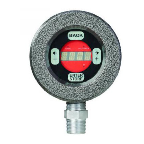
U2-S Model Combination Viewing
Head and Signal Processor
WARNING
WARNING
WARNING
Read the instructions before use. This control shall be
installed in accordance with the rules in force.
Additional versions of this manual are available online
at https://customer.honeywell.com/en-
US/Pages/default.aspx in Canadian French,
Portuguese, and German. Please enter 32-00015 in the
search box and choose Technical Literature from the
drop-down box.
AVERTISSEMENT
AVERTISSEMENT
Lire les instructions avant l'utilisation. Cette
commande doit être installée conformément aux lois
en vigueur. Des versions supplémentaires de ce manuel
sont disponibles enligne à
https://customer.honeywell.com/en-
US/Pages/default.aspx en français du Canada, en
portugais et en allemand. Veuillez inscrire 32-00015
dans le casier de recherche et choisissez
Documentation technique à partir du menu déroulant.
WARNUNG
Lesen Sie vor der Verwendung die Anweisung. Diese
Konsole muss entsprechend den geltenden
Vorschriften installiert werden. Zusätzliche Versionen
dieses Handbuchs sind online unter
https://customer.honeywell.com/en-
US/Pages/default.aspx in Frankokanadisch,
Portugiesisch und Deutsch verfügbar. Bitte geben Sie
im Suchfeld 32-00015 ein und wählen Sie Fachliteratur
im Drop-Down Menü aus
ATENÇÃO
Leia as instruções antes de usar. Esse controle tem que
ser instalado de acordo com as normas vigentes.
Outras versões desse manual estão disponíveis online
em https://customer.honeywell.com/en-
US/Pages/default.aspx em francês do Canadá,
português e alemão. Insira 32-00015 em cada caixa e
selecione Literatura Técnica na caixa suspensa.
Disposal and Recycling
Waste electrical products should not be disposed
of with general waste. Please recycle where these
facilities exist. Check with your local authority for
recycling advice.
GENERAL INFORMATION
The Honeywell U2-101xS series model is a viewing head
and signal processor in a single enclosure intended for
use with a burner control system in Industrial Flame
Monitoring applications. There are several options
available (see Table 1 on page 2). Each model includes
one, two, or all three sensors, and can be ordered with
quick disconnect (non-PF Models DIV2,ZN2) or pigtail
external connection method (PF Models DIV1,ZN1).
Each sensor operates independently from another,
allowing adjustment of each sensor.
IMPORTANT
Flame monitoring systems are safety systems.
Please read this manual carefully and completely
before installation and before attempting adjust-
ments.
Only qualified personnel familiar with Flame
Safety System should carry out installation and
configuration.
U2 is certified to be used in prescribed manner.
Any modification or inappropriate installation or
operation may result in unsafe operation and will
void implied or expressed warranty.
Sensors
The UV tube detector has a peak response at 210 nm.
The IR solid state sensor has a peak response at 1400 nm.
The UV solid state sensor has a peak response at 310 nm.
Cabling Options (Sold Separately)
ASYU2S - Quick Disconnect (non-PF) models molded
connector cable assembly with 50 foot of C22S cable.
ASYU2S-100 - Quick Disconnect (non-PF) models molded
connector cable assembly with 100 foot of C22S cable.
ASYU2S-200 - Quick Disconnect (non-PF) models molded
connector cable assembly with 200 foot of C22S cable.
ASYU2S-300 - Quick Disconnect (non-PF) models molded
connector cable assembly with 300 foot of C22S cable.
C22S - Raw shielded 12 conductor, 22g, ITC, CIC
approved. Order by the foot.
USER MANUAL
32-00015-05
Advertisement
Table of Contents

Related Manuals for Honeywell U2-S


Summary of Contents for Honeywell U2-S
- Page 1 Head and Signal Processor USER MANUAL GENERAL INFORMATION The Honeywell U2-101xS series model is a viewing head and signal processor in a single enclosure intended for use with a burner control system in Industrial Flame Monitoring applications. There are several options available (see Table 1 on page 2).
-
Page 2: Specifications
U2-S MODEL COMBINATION VIEWING HEAD AND SIGNAL PROCESSOR Table 1. Models and Associated Features. Sensor Type Quick Pipe Fit Model Connector Connection UVTron UVSS Typical Fuels U2-1010S All Fuels U2-1010S-PF All Fuels U2-1010S-PF-050* All Fuels U2-1010S-PF-100 All Fuels U2-1012S Oil and Coal... -
Page 3: Installation
U2-S MODEL COMBINATION VIEWING HEAD AND SIGNAL PROCESSOR PF version Non-PF/ General Color Function Connection FM, CSA, CE (EN298), and EAC 9-Tan File Select Output, 0 or +24V To burner control Hazardous Location output. Feedback for system system. 0V = File Select controlling file input select. -
Page 4: Location/Mounting On Burner
25 mm The U2-S model viewing port is designed for interface to a WC (1" wc) above back pressure at all the time, from 1" NPT (M) fitting. The viewing head can be mounted in minimum to maximum load. - Page 5 U2-S MODEL COMBINATION VIEWING HEAD AND SIGNAL PROCESSOR HIGH FREQUENCY FLICKER ZONE DETECTOR IN GOOD SIGHTING POSITION (PARALLEL SIGHTING) BURNER NOZZLE CENTERLINE DETECTOR IN POOR SIGHTING POSITION LOW FREQUENCY FLICKER ZONE M33285B Fig. 3. IR viewing head location. UV VIEWING...
-
Page 6: Mounting Accessories
File Input Select Value File Select Output Value extension. Refer to Honeywell manual 69-2683 3. U2-S supports Modbus protocol. The system can be monitored using user's hardware and software and/or Honeywell FlameTool for PC or Honeywell FlameTool for Panel (S7999). For detail refer to man- There are several parameter adjustments that permit ual 32-00001 and 32-00003. -
Page 7: U2 Menu Parameter Settings
U2-S MODEL COMBINATION VIEWING HEAD AND SIGNAL PROCESSOR NOTE: Only the pertinent menu will be displayed. For 20mA at 3425 counts. The ma gain setting allows for example, for UVtron only sensor (U2-1016S and scaling of the analog output value proportional to the U2-1016S-PF), only UVTron gain will be dis- flamecount at full load. -
Page 8: File Selection
U2-S MODEL COMBINATION VIEWING HEAD AND SIGNAL PROCESSOR File Selection Panel Timeout The Time Out sub-menu allows for adjustment to a *F0X - The U2 is able to store up to 8 different file secondary safety feature that locks the U2 interface (configurations) (file0 - file7). - Page 9 U2-S MODEL COMBINATION VIEWING HEAD AND SIGNAL PROCESSOR NOTE: While using the Auto Gain and Auto Filter modes, Register Read the system will be adjusting to the firing condi- Address Register Description Write tions at the time of implementation. This condi-...
-
Page 10: Troubleshooting
U2-S MODEL COMBINATION VIEWING HEAD AND SIGNAL PROCESSOR Important Information Lockout Failure Code Cause Action 1. When connected to an approved Burner control Sys- UVTUBE UVtube sensor supply failure. Device must be tem, additional EMC tests are not required. SENSOR replaced. -
Page 11: U2-S Flame Threshold Setup
U2-S MODEL COMBINATION VIEWING HEAD AND SIGNAL PROCESSOR U2-S Flame Threshold Setup 5. Extinguish target flame while maximum background radiation is present. Observe flamecount, and Desired target burner flamecount during normal increase filter setting(s) of sensor(s) to decrease operation is 1200 to 2000 counts. - Page 12 U2-101xS FLAMESCANNER SELF FLAME CHECK RELAY RELAY SCREW TO EARTH GROUND (GREY) FLAME SIGNAL OUTPUT 30VDC 1A MAX (GREEN) FAULT SIGNAL OUTPUT 30VDC 1A MAX BURNER CONTROL SYSTEM (PURPLE) FILE SELECT INPUT 30VDC MAX (TAN) FILE SELECT OUTPUT 24VDC 10ma MAX (ORANGE) mA OUPUT + 500Ω...
-
Page 13: Safety Manual
U2-S MODEL COMBINATION VIEWING HEAD AND SIGNAL PROCESSOR SAFETY MANUAL U2-S Model Product Declaration FIT FOR USE IN A LOW DEMAND SAFETY APPLICATION Models:U2-1010S, U2-1012S, U2-1016S, U2-1018S, U2-1010S-PF, U2-1012S-PF, U2-1016S-PF, U2-1018S-PF λ λ λ Models SIL HFT U2-1010S/U2-1010S-PF >99% 1.20 x10 1.23x10... -
Page 14: Safety Function Of The U2-S Model
Setup and gray wires. 4. Remove any light source to generate a flame off con- 1. Set power supply to OFF. Connect U2-S model to dition and, using a multimeter measure resistance power supply as described in manual. between green and gray wires, and verify flame relay 2. -
Page 15: Product Decommissioning
U2-S MODEL COMBINATION VIEWING HEAD AND SIGNAL PROCESSOR 7. Use your light source to generate flamecounts of 8. Restore all original settings as recorded in setup and between 1200 and 2000 in the signal processor. reconnect the signal processor to the safety system. - Page 16 U2-S MODEL COMBINATION VIEWING HEAD AND SIGNAL PROCESSOR Home and Building Technologies In the U.S.: Honeywell 715 Peachtree Street NE Atlanta, GA 30308 customer.honeywell.com Honeywell MAXON branded products 201 E 18th Street Muncie, IN 47302 www.maxoncorp.com Belgium Maxon International BVBA...