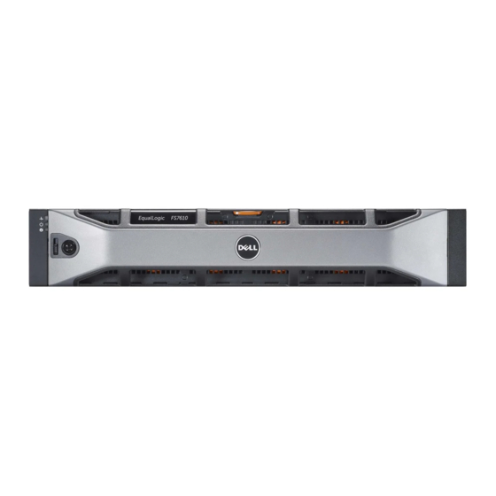
Dell EqualLogic FS7610 Series Hardware Owner's Manual
Appliances
Hide thumbs
Also See for EqualLogic FS7610 Series:
- Overview (7 pages) ,
- Installation and setup manual (46 pages)
Table of Contents
Advertisement
Advertisement
Table of Contents

Related Manuals for Dell EqualLogic FS7610 Series


Summary of Contents for Dell EqualLogic FS7610 Series
- Page 1 Dell EqualLogic FS7610 Series Appliances Hardware Owner's Manual...
- Page 2 All trademarks and registered trademarks mentioned herein are the property of their respective owners. Information in this document is subject to change without notice. Reproduction in any manner whatsoever without the written permission of Dell is strictly forbidden. Published: October 2013...
-
Page 3: Table Of Contents
Table of Contents Preface 1 Basic Appliance Information Appliance Components Connecting an Appliance to Power Turning Power On and Off Required Tools Technical Specifications 2 Replacing Components Safety Recommendations Required Tools Using an Electrostatic Wrist Strap Replacing a Controller Installing a Controller Replacing SFP+ Transceivers Replacing a Power Supply Replacing a Cooling Fan... - Page 4 Dell EqualLogic FS7610 Hardware Owner's Manual...
-
Page 5: Preface
Technical Support and Customer Service Dell support service is available to answer your questions about PS Series SAN arrays and FS Series appliances. Contacting Dell If you are a customer in the United States or Canada in need of technical support, call 1-800-945-3355. If you are outside of the United States or Canada, visit support.dell.com/support/topics/global.aspx. - Page 6 Dell EqualLogic FS7610 Hardware Owner's Manual Preface Note, Caution, and Warning Symbols A NOTE symbol indicates important information that helps you make better use of your hardware or software. A CAUTION symbol indicates potential damage to hardware or loss of data if instructions are not followed.
-
Page 7: Basic Appliance Information
1 Basic Appliance Information This chapter contains information about the location and basic operation of the components in a Dell™ EqualLogic® FS7610 NAS appliance. The chapter also includes general operating procedures such as power ON and power OFF operations, and how to return failed components. - Page 8 Dell EqualLogic FS7610 Hardware Owner's Manual 1 Basic Appliance Information LED Indicator Icon State and Description Power-On The power LED lights green when at least one power supply is connected to a Indicator power source and is supplying power to the system.
- Page 9 Right: Controller 2 Serial COM port (mini USB connector). Allows you to connect a serial device to the system. This connector is for service only. Use this connector only if asked to do so by Dell support. USB port Video port...
-
Page 10: Connecting An Appliance To Power
Dell EqualLogic FS7610 Hardware Owner's Manual 1 Basic Appliance Information LED Indicator/ Icon State and Description Button Solid green—The controller is clustered and fully functional. Alternating blinking amber/green—The expected hardware configuration does not match the actual hardware. Unlit—Controller is in power OFF mode. -
Page 11: Turning Power On And Off
Dell EqualLogic FS7610 Hardware Owner's Manual 1 Basic Appliance Information Figure 4: Secure the Power Cable with the Strain Relief The appliance turns on as soon as the power supplies are connected to a live power source. Each controller contains a backup power supply (BPS). The BPS batteries begin to charge when the appliance is connected to power. -
Page 12: Required Tools
Dell EqualLogic FS7610 Hardware Owner's Manual 1 Basic Appliance Information Turning Controller Power Off If you need to replace a controller, turn off the power to start a shutdown. Use a small, thin tool such as a #1 Phillips screwdriver to press and release the power LED button on the back of the controller you plan to remove. - Page 13 Dell EqualLogic FS7610 Hardware Owner's Manual 1 Basic Appliance Information 90 VAC to 264 VAC, autoranging, 47 Hz/63 Hz Voltage This system is also designed to be connected to IT power systems with a phase to phase voltage not exceeding 230 V.
- Page 14 Dell EqualLogic FS7610 Hardware Owner's Manual...
-
Page 15: Replacing Components
2 Replacing Components This chapter describes how to replace appliance components or the entire appliance. Safety Recommendations Follow these safety recommendations: • Before you work on the EqualLogic FS7610 hardware, read and follow the safety instructions packaged with your system. •... -
Page 16: Replacing A Controller
Damage due to servicing that is not authorized by Dell is not covered by your warranty. Read and follow the safety instructions that came with the product. -
Page 17: Installing A Controller
Dell EqualLogic FS7610 Hardware Owner's Manual 2 Replacing Components Figure 7: Removing a Controller 6. Pull the handle down and out. See callouts 2, 3, and 4 in Figure 7. Support the controller with two hands, and place it on an antistatic surface. -
Page 18: Replacing Sfp+ Transceivers
Removing an SFP+ Transceiver 1. Stop all system access (such as application, system I/O, or RAW device file paths). If you are replacing or changing transceivers on a system that cannot be shut down, contact Dell Technical Support Services at eqlsupport.dell.com... -
Page 19: Replacing A Power Supply
Although the appliance continues to function with only one working power supply, Dell recommends that you replace a failed power supply as soon as possible. The second power supply ensures continued operation and high availability in the event of a power or power supply failure. - Page 20 Dell EqualLogic FS7610 Hardware Owner's Manual 2 Replacing Components Figure 10: Removing a Power Supply Installing a Power Supply 1. Slide the new power supply into the appliance until the release latch clicks into place. See Figure 2. Connect the power cord to the power supply, then connect the other end to the power source.
- Page 21 Dell EqualLogic FS7610 Hardware Owner's Manual 2 Replacing Components 2. Push up on the release latch on the left side of the bezel and carefully pull out the bezel from the left side of the chassis (callout 1). 3. Move the bezel to the left to disengage it from the right side of the chassis (callouts 2 and 3).
-
Page 22: Replacing A Cooling Fan
Damage due to servicing that is not authorized by Dell is not covered by your warranty. Read and follow the safety instructions that came with the product. - Page 23 Dell EqualLogic FS7610 Hardware Owner's Manual 2 Replacing Components 3. Press the fan release tabs (Figure 15 callout 1) and pull the cooling fan out of the NAS appliance chassis (callout 2). Figure 15: Removing a Cooling Fan Installing a Fan 1.
-
Page 24: Replacing The Appliance
Removing the appliance will cause the entire NAS cluster to be lost, requiring you to rebuild the NAS cluster from scratch. Before replacing the entire NAS appliance, contact Dell technical support to assess the situation. In most cases, replacing the power supply units or control modules will resolve issues. -
Page 25: What To Do Next
Group Manager online help describes how to use the Group Manager graphical user interface (GUI) to manage a NAS cluster. The Dell EqualLogic Group Manager Administrator's Manual and the Group Manager command line interface (CLI) help describe how to use the CLI to manage a NAS cluster. - Page 26 Dell EqualLogic FS7610 Hardware Owner's Manual...
-
Page 27: Appendix A: Nom Information (Mexico Only)
Mexican standards (NOM). Table 7: NOM Information for Mexico Norma Oficial Mexicana Dell México S.A. de C.V. Paseo de la Reforma 2620 -- 11° Piso Importer Col. Lomas Altas 11950 México, D.F. - Page 28 Dell EqualLogic FS7610 Hardware Owner's Manual...
-
Page 29: Glossary
NFS exports on a NAS container and share them with authorized users. A NAS cluster supports multiple NAS containers. NAS appliance Dell hardware that contains two controllers that must be paired together when configured into a NAS cluster. After an appliance is configured, it becomes a NAS member. - Page 30 Glossary: –...
- Page 31 appliance installation dimensions safety precautions front and back panels specifications weight LEDs back panel controller back-panel features front panel back-panel LEDs backup power supply (BPS) bezel attaching NAS cluster key lock on controller documentation removing post-configuration tasks controller power location on back panel turning on the controller cooling fan power supply unit (PSU)
- Page 32 Index: appliance – Group Manager GUI...