Dell EqualLogic PS4000 Hardware Maintenance
Storage arrays
Hide thumbs
Also See for EqualLogic PS4000:
- Configuration manual (73 pages) ,
- Instructions manual (14 pages) ,
- Installation and setup manual (51 pages)
Table of Contents
Advertisement
Advertisement
Table of Contents

Related Manuals for Dell EqualLogic PS4000


Summary of Contents for Dell EqualLogic PS4000
- Page 2 All trademarks and registered trademarks mentioned herein are the property of their respective owners. Information in this document is subject to change without notice. Reproduction in any manner whatsoever without the written permission of Dell is strictly forbidden. April 2009...
-
Page 3: Table Of Contents
Table of Contents Preface ........................v Audience ......................v Organization ....................v Documentation ....................vi Technical Support and Customer Service .............vii Warranty Information .................. viii 1 Basic Storage Array Information..............1-1 Array Front and Back Panels................ 1-1 Interpreting Operations Panel LEDs ............1-2 Using an Electrostatic Wrist Strap ............... 1-5 Shutting Down and Restarting an Array ............ - Page 4 PS4000 Hardware Maintenance Table of Contents Replacing a Micro SD Card..............3-18 4 Maintaining Power Supply Modules............4-1 Interpreting the LEDs................... 4-1 Identifying Failures ..................4-1 Removing a Power Supply and Cooling Module......... 4-2 Installing a Power Supply and Cooling Module .......... 4-4 A Environmental, Power, and Other Specifications........A-1 Index......................Index-1...
-
Page 5: Preface
Preface This manual describes how to maintain the hardware for PS4000 storage arrays. Each array contains hot-swappable power supply and cooling modules, eight or sixteen RAID-protected disks, and single or dual hot-swappable control modules. With one or more PS Series arrays, you can create a PS Series group—a self- managing, iSCSI storage area network (SAN) that is affordable and easy to use, regardless of scale. -
Page 6: Documentation
• PS Series Release Notes. Provides the latest information about PS Series arrays. • Dell EqualLogic PS Series Array End User License Agreement (EULA) • Warranty and Support Information (WSI) • Safety, Environmental, and Regulatory Information (SERI) •... -
Page 7: Technical Support And Customer Service
Preface Technical Support and Customer Service Dell’s support service is available to answer your questions about PS Series arrays. If you have an Express Service Code, have it ready when you call. The code helps Dell’s automated-support telephone system direct your call more efficiently. -
Page 8: Warranty Information
PS4000 Hardware Maintenance Preface • (Latin American countries) www.dell.com/la • (Canada only) www.dell.ca You can access Dell Support through the following websites: • support.dell.com • support.dell.com/EqualLogic • (Japan only) support.jp.dell.com • Europe only) support.euro.dell.com ( Warranty Information The PS4000 array warranty is included in the shipping box. For information about registering a warranty, visit support.dell.com/EqualLogic... -
Page 9: Basic Storage Array Information
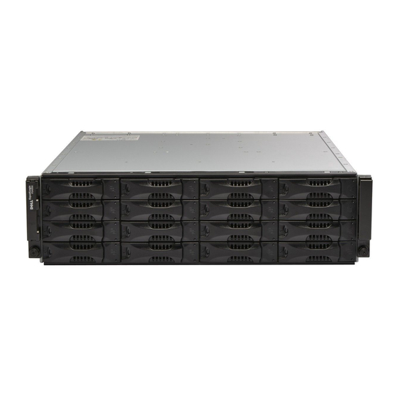
1 Basic Storage Array Information This chapter includes basic information about PS4000 storage arrays. Array Front and Back Panels The front of a PS4000 array is shown in Figure 1-1 and Figure 1-2. Figure 1-1: PS4000 Front Panel (with Bezel) Figure 1-2: PS4000 Front Panel (without Bezel) The disk drives are accessible from the front, after you remove the bezel. -
Page 10: Interpreting Operations Panel Leds
PS4000 Hardware Maintenance Basic Array Information Figure 1-3: PS4000 Back Panel Table 1-1: Back Panel Detail Description Item Description Power supply and cooling modules. The module on the right is 0, and the module on the left is 1. Control modules. The module on the right is 0, and the module on the left is 1. Operation panel LED. - Page 11 PS4000 Hardware Maintenance Basic Array Information For information about other array LEDs, see Interpreting Disk Drive LEDs on page 2-3, Interpreting Control Module LEDs on page 3-2, and Interpreting the LEDs on page 4-1. Figure 1-4: Operations Panel Table 1-2: Operations Panel Descriptions Item Status Description...
- Page 12 PS4000 Hardware Maintenance Basic Array Information Table 1-2: Operations Panel Descriptions (Continued) Item Status Description No power or normal condition. Flashing orange One or more of the following has occurred: Warning • RAID set is degraded but still functioning. condition •...
-
Page 13: Using An Electrostatic Wrist Strap
PS4000 Hardware Maintenance Basic Array Information Table 1-2: Operations Panel Descriptions (Continued) Item Status Description This label contains the serial number for your array. If you contact your PS Series support provider, you may need to provide this number. Serial number label Using an Electrostatic Wrist Strap When handling the array chassis, disk drives, or control modules, you must use an... - Page 14 Password: Welcome to Group Manager Copyright 2001-2009 Dell, Inc. group1> shutdown If you are using a serial connection to shut down an array, it is safe to turn off power when the “press any key” message appears. (Pressing any key will restart both control modules.)
-
Page 15: Maintaining Disk Drives
2 Maintaining Disk Drives The array includes up to 16 hot-swappable disk drives, either Serial Attached SCSI (SAS) or Serial ATA (SATA). Disk drive maintenance topics apply to both SAS and SATA disk drives. Removing the Bezel To access the disk drives, you must remove the bezel. The bezel comes with a lock, which helps protect the disk drives from being tampered with or accidentally removed. - Page 16 PS4000 Hardware Maintenance Maintaining Disks Figure 2-2: Pushing Up the Bezel Release Latch 3. Hold the bezel and pull it away from the chassis. See Figure 2-3. Figure 2-3: Detaching the Bezel from the Chassis 2–2...
-
Page 17: Interpreting Disk Drive Leds
PS4000 Hardware Maintenance Maintaining Disks Interpreting Disk Drive LEDs Figure 2-4 shows how disk drives are oriented and numbered in the array. Figure 2-4: Disk Drive Numbering The parts of a disk drive are shown in Figure 2-5 and described in Table 2-1. Figure 2-5: Disk Drive Detail Table 2-1: Disk Drive Detail Descriptions Callout... -
Page 18: Disk Drive Handling Requirements
PS4000 Hardware Maintenance Maintaining Disks Table 2-1: Disk Drive Detail Descriptions (Continued) Callout Item Color Description Error LED No power or normal condition. Error condition. Disk Drive Handling Requirements Handle disk drives as follows: • Store drives properly. Store replacement disk drives in the packaging in which they were shipped. -
Page 19: Array Behavior When A Disk Drive Fails
PS4000 Hardware Maintenance Maintaining Disks • The GUI Member Disks window or the CLI member select show disks command shows a disk drive failure. Array Behavior When a Disk Drive Fails How an array handles a disk drive failure depends on whether a spare disk drive is available and whether the RAIDset containing the failed disk drive is degraded. - Page 20 PS4000 Hardware Maintenance Maintaining Disks To remove a disk drive: 1. Press the handle release button to the left, in the direction of the arrow, to disangage the handle. 2. Grasp the handle and pull the disk drive 2.5 cm (1 inch) from the slot. See Figure 2-6.
-
Page 21: Disk Drive Installation Guidelines And Restrictions
PS4000 Hardware Maintenance Maintaining Disks Disk Drive Installation Guidelines and Restrictions • Install only disk drives of the same type, speed, and spin rate in an array. The color of the handle release button indicates the disk drive type (black for SAS; gray for SATA). -
Page 22: Installing The Bezel
PS4000 Hardware Maintenance Maintaining Disks 2. Press the handle release button to release the handle. Open the handle. 3. With the handle at an angle, slide the disk drive completely into the slot, simultaneously pushing in the handle until you hear a click. See Figure 2-7. Figure 2-7: Closing the Disk Drive Handle Verify that the new disk drive is operational by examining the LEDs on the front panel, as described in Interpreting Disk Drive LEDs on page 2-3. - Page 23 PS4000 Hardware Maintenance Maintaining Disks 2. Push the bezel toward the chassis until the left side of the bezel engages with the chassis. 3. Insert the bezel key and turn it counter-clockwise to lock the bezel. 4. Store the key in a safe place. 2–9...
-
Page 25: Maintaining Control Modules
3 Maintaining Control Modules A PS4000 array includes one or two hot-swappable control modules. One functioning control module is required for array operation. You access control modules from the rear of the array. Control Modules A PS4000 array includes either two Type 8 or two Type 9 control modules.See Figure 3-1 and Figure 3-2. -
Page 26: Interpreting Control Module Leds
PS4000 Hardware Maintenance Maintaining Control Modules module. If the active control module fails, the secondary will take over network operations. Do not mix control module types in an array. Always make sure both control modules are the same type and color. See the latest PS Series Release Notes for information about other supported control modules. -
Page 27: Identifying Control Module Failures
PS4000 Hardware Maintenance Maintaining Control Modules Table 3-2: Ethernet Port LED Descriptions LED Location Color Description Left side of each No power or not connected to network. port Green Connected to network. Right side of each No power, not transmitting, or not receiving. port Green Transmitting or receiving. -
Page 28: Maintaining Control Module Firmware
PS4000 Hardware Maintenance Maintaining Control Modules A PS series array provides two types of network failure protection: • Network connection failover. If multiple network interfaces are configured and one network interface fails, iSCSI initiators that were connected to the failed interface can reconnect to the group IP address and be redirected to a functioning interface. -
Page 29: Network Configuration Recommendations
Maintaining Control Modules Network Configuration Recommendations Dell recommends that you follow the guidelines in Table 3-3. In addition, all the usual rules for proper network configuration apply to group members. General network configuration is beyond the scope of this manual. -
Page 30: Connecting Network Cables
PS4000 Hardware Maintenance Maintaining Control Modules Table 3-3: Network Recommendations (Continued) Recommendation Description No STP functionality If possible, do not use Spanning-Tree (STP) on switch ports that on switch ports that connect end nodes (iSCSI initiators or storage array network connect end nodes interfaces). - Page 31 For a single control module array, the minimum network configuration is one network connection to Ethernet 0. However, the single network connection is a potential point of failure and limits bandwidth. Dell recommends that you connect Ethernet 0 and Ethernet 1 to different network switches.
- Page 32 PS4000 Hardware Maintenance Maintaining Control Modules example, if the network cable connected to the active control module is disconnected). Figure 3-4 shows the minimum network configuration for a dual control module array. Cables are connected to Ethernet 0 on both control modules. Figure 3-4: Minimum Network Configuration Figure 3-5 shows the recommended network configuration for a dual control module array, which is to connect Ethernet 0 and Ethernet 1 to different switches,...
-
Page 33: Control Module Handling Requirements
PS4000 Hardware Maintenance Maintaining Control Modules Figure 3-5: Recommended Network Configuration Control Module Handling Requirements Follow these control module handling requirements: • Protect control modules from electrostatic discharge. Always wear an electrostatic wrist strap when handling a control module, as described in Using an Electrostatic Wrist Strap on page 1-5. - Page 34 PS4000 Hardware Maintenance Maintaining Control Modules You may need to temporarily remove a control module to replace its compact flash or micro SD card. Notes: For proper cooling, do not leave a control module slot empty. If an array will operate for a long time with only one control module, you must install a blank control module in the empty slot.
- Page 35 PS4000 Hardware Maintenance Maintaining Control Modules Figure 3-6: Opening a Control Module Latch 2. Hold the latches and carefully slide the control module from the slot. See Figure 3-7. 3–11...
- Page 36 PS4000 Hardware Maintenance Maintaining Control Modules Figure 3-7: Removing a Control Module 3. Place the control module on a flat surface where it will be protected from electrostatic charge. Caution: To avoid damage, do not place anything on top of the control module. 4.
-
Page 37: Installing A Control Module
PS4000 Hardware Maintenance Maintaining Control Modules Return the failed control module in the packaging in which the replacement module was shipped. Contact your PS Series support provider for information about returning hardware. Installing a Control Module You can install a control module without shutting down the array. Caution: Do not mix control module types in an array. - Page 38 PS4000 Hardware Maintenance Maintaining Control Modules Figure 3-9: Installing a Control Module 5. Connect the network cables as described in Connecting Network Cables on page 3-6. 6. If the array was shut down, turn on power to the array. 7. Examine the LEDs, as described in Interpreting Control Module LEDs on page 3-2.
-
Page 39: Replacing The Firmware Card
PS4000 Hardware Maintenance Maintaining Control Modules charged, as soon as the battery status is , you can good/charging temporarily disable the low-battery-safe policy and force the array to operate in write-back mode. Make sure to re-enable the low-battery-safe policy when the battery is fully charged. See the PS Series Group Administration manual for information about cache policies. -
Page 40: Replacing A Compact Flash Card
PS4000 Hardware Maintenance Maintaining Control Modules Replacing a Compact Flash Card 1. Firmly grasp the sides of the card and slide it from the connector. Make sure not to damage the card or the control module circuit board. See Figure 3-10. Figure 3-10: Removing a Compact Flash Card 2. - Page 41 PS4000 Hardware Maintenance Maintaining Control Modules Figure 3-11: Inserting a Compact Flash Card 3. Firmly press the compact flash card into place. 4. Install the control module. See Installing a Control Module on page 3-13. 3–17...
-
Page 42: Replacing A Micro Sd Card
PS4000 Hardware Maintenance Maintaining Control Modules Replacing a Micro SD Card 1. Firmly push the card into its housing to release the spring mechanism (Figure 3-12). The micro SD card will be partially ejected from the housing. Figure 3-12: Ejecting the Micro SD Card 2. - Page 43 PS4000 Hardware Maintenance Maintaining Control Modules 5. Firmly press the card into the housing until it clicks into place. Make sure you cannot pull it out. Figure 3-13: Inserting the Micro SD Card 6. Install the control module. See Installing a Control Module on page 3-13. After you replace the micro SD card, make sure the control module is operational.
-
Page 45: Maintaining Power Supply Modules
4 Maintaining Power Supply Modules The array includes two hot-swappable, combination power supply and cooling modules. Interpreting the LEDs Use the power supply and cooling module LEDs, shown in Figure 4-1 and described in Table 4-1, to determine the module status and identify problems. The power supply and cooling module LEDs show the power, fan, and array status. -
Page 46: Removing A Power Supply And Cooling Module
PS4000 Hardware Maintenance Maintaining Power Supply Modules • Group Manager GUI and CLI output. The GUI Member Enclosure window or the CLI command shows a member select show enclosure power supply and cooling module failure. Note: When viewing the rear of the array, power supply 0 is on the right, and power supply 1 is on the left. - Page 47 PS4000 Hardware Maintenance Maintaining Power Supply Modules Figure 4-2: Releasing the Handle 4. Hold the handle and pull the module from the slot. See Figure 4-3. Caution: The module is heavy; support it with two hands. Figure 4-3: Removing a Power Supply and Cooling Module 4–3...
-
Page 48: Installing A Power Supply And Cooling Module
PS4000 Hardware Maintenance Maintaining Power Supply Modules Installing a Power Supply and Cooling Module Caution: The module is heavy; support it with two hands. To install a power supply and cooling module in an array: 1. Attach an electrostatic wrist strap, as described in Using an Electrostatic Wrist Strap on page 1-5. - Page 49 PS4000 Hardware Maintenance Maintaining Power Supply Modules 6. Use the cable strain relief to secure the power cable to the array, as shown in Figure 4-5. Note: If you need to reverse the cable strain relief wire for your power cable configuration, press the wire ends together as shown in Figure 4-5 to disengage the wire from the power plug socket.
- Page 50 PS4000 Hardware Maintenance Maintaining Power Supply Modules module initialization can take from one to ten seconds. When complete, the power LED is green and an event message states that fans have returned to their normal speed. 4–6...
-
Page 51: A Environmental, Power, And Other Specifications
A Environmental, Power, and Other Specifications Table A-2 describes the environmental, power, and physical specifications for a PS4000 array. Table A-2: PS4000 Array Specifications Component Requirement Weight of fully-loaded array 35 kg (77.6 lb) Operating temperature 5 to 35 °C (41 to 95 °F) Storage temperature -30 to 60 °C (-22 to 140 °F) Maximum operating altitude... -
Page 53: Index
Index failure indications 3-3 firmware identification 3-4 array firmware requirements 3-4, 3-13, back panel 1-2 3-15 batteries 3-1 handling requirements 3-9 control module restriction 3-13 installing in array 3-13 control modules 3-1 LEDs 3-2 cooling 4-1 locating 3-3 disk types 2-3 micro SD card, replacing 3-4, 3-15 environmental requirements A-1 removing from array 3-9... - Page 54 PS4000 Hardware Maintenance Index verifying operational status 2-8 LEDs control module 3-2 electrostatic protection, using 1-5 cooling modules 4-1 environmental requirements A-1 disks 2-3 network interfaces 3-2 operations panel 1-2 failover power supplies 4-1 control module 3-3, 3-4 network connection 3-4 failure indications member array 1-2...
- Page 55 PS4000 Hardware Maintenance Index power cables supported control module 3-1 restriction 4-4 SATA disks power supplies identifying 2-3 cable strain relief 4-5 supported control module 3-1 indications of failure 4-1 serial number label 1-2, 1-5 initialization 4-5 shutting down an array 1-5 installing module in array 4-4 LEDs 4-1 Spanning-Tree recommendation 3-6...