Table of Contents
Advertisement
Quick Links
NF632E Series
User Manual
NO. G03-NF632E-F
Revision: 6.0
Release date: October 12, 2018
Trademark:
* Specifications and Information contained in this documentation are furnished for information use only, and are
subject to change at any time without notice, and should not be construed as a commitment by manufacturer.
Advertisement
Table of Contents

Related Manuals for JETWAY NF632E Series


Summary of Contents for JETWAY NF632E Series
- Page 1 NF632E Series User Manual NO. G03-NF632E-F Revision: 6.0 Release date: October 12, 2018 Trademark: * Specifications and Information contained in this documentation are furnished for information use only, and are subject to change at any time without notice, and should not be construed as a commitment by manufacturer.
- Page 2 Environmental Protection Announcement Do not dispose this electronic device into the trash while discarding. To minimize pollution and ensure environment protection of mother earth, please recycle.
-
Page 3: Table Of Contents
TABLE OF CONTENT ENVIRONMENTAL SAFETY INSTRUCTION ................iv USER’S NOTICE ........................v MANUAL REVISION INFORMATION ..................v ITEM CHECKLIST ........................v CHAPTER 1 INTRODUCTION OF THE MOTHERBOARD FEATURE OF MOTHERBOARD ................1 SPECIFICATION ......................2 LAYOUT DIAGRAM ....................3 CHAPTER 2 HARDWARE INSTALLATION JUMPER SETTING ..................... -
Page 4: Environmental Safety Instruction
Environmental Safety Instruction l Avoid the dusty, humidity and temperature extremes. Do not place the product in any area where it may become wet. l 0 to 40 centigrade is the suitable temperature. (The figure comes from the request of the main chipset) l Generally speaking, dramatic changes in temperature may lead to contact malfunction and crackles due to constant thermal expansion and contraction from the welding spots’... -
Page 5: User's Notice
USER’S NOTICE COPYRIGHT OF THIS MANUAL BELONGS TO THE MANUFACTURER. NO PART OF THIS MANUAL, INCLUDING THE PRODUCTS AND SOFTWARE DESCRIBED IN IT MAY BE REPRODUCED, TRANSMITTED OR TRANSLATED INTO ANY LANGUAGE IN ANY FORM OR BY ANY MEANS WITHOUT WRITTEN PERMISSION OF THE MANUFACTURER. -
Page 6: Chapter 1 Introduction Of The Motherboard
Chapter 1 Introduction of the Motherboard 1-1 Feature of Motherboard ® n Onboard high-performance Intel Skylake-U series SoC CPU n Support 2 * DDR4 2133MHz Dual Channel SO-DIMM, max up to 32GB n Support HDMI, Display Port, LVDS, eDP Triple Independent Displays n Support 1 * SATAIII (6Gb/s) device n Onboard 1* full-size Mini-PCIE/M-SATA share slot device n Onboard 1* half-size Mini-PCIE device... -
Page 7: Specification
Specification Spec Description 3.5” SBC Form Factor; PCB size: 148mm * 102mm Design ® Integrated with Intel Skylake-U series CPU;TDP:15W Embedded CPU *CPU model varies from different IPC options. Please consult your dealer for more information of onboard CPU. 2*DDR4 SO-DIMM slot support 2* DDR4 2133 MHz SO-DIMM up to 32GB Memory Slot Support dual channel function... -
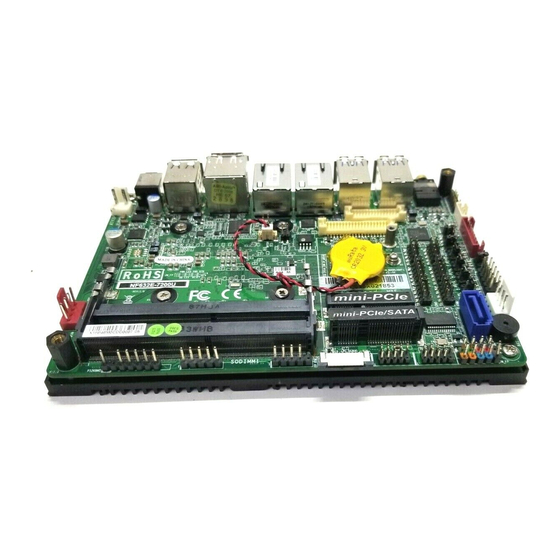
Page 8: Layout Diagram
1* 3W amplifier header 1* Front panel header 2* 9-pin USB 2.0 header (Expansible to 4* USB 2.0 ports) 1* 4-pin USB 2.0 header (Expansible to 1* USB 2.0 port) 1* SMBUS header 1* PS/2 keyboard & mouse header 1* GPIO header 1* RS232/422/485 serial port header (COM1) 5* RS232 serial port header (COM2/3/4/5/6) 1* LAN LED activity header... - Page 9 Motherboard Internal Diagram-Front Side...
- Page 10 Motherboard Internal Diagram-Back Side *Intel CPU Note: CPU is the most important part of the board and very fragile to any possible harm. Make sure that there is no damage to the CPU during any installation procedures!
- Page 11 Jumper Positions:...
- Page 12 Jumper Jumper Name Description COM1 Header Pin9 Function Select 4-pin Block COM2 Header Pin9 Function Select 4-Pin Block COM3 Header Pin9 Function Select 4-Pin Block COM4 Header Pin9 Function Select 4-Pin Block LVDS Header VCC 3.3V/5V/12V Select 4-Pin Block LVDS INVERTER Backlight 5V/12V Select 4-Pin Block AT_COPEN Pin (1&2): ATX Mode / AT Mode Select 4-Pin Block...
- Page 13 Headers Header Name Description FP_AUDIO Front Panel Audio Header 9-pin Block SPEAK_CON 3W Amplifier Header 4-pin Block JW_FP Front Panel Header(PWR LED/ HDD 9-pin Block LED/Power Button /Reset) FP_USB20/ USB 2.0 Header 9-pin Block FP_USB21 FP_USB USB 2.0 Header 4-pin Block SMBUS SMBUS Header 5-pin Block...
-
Page 14: Chapter 2 Hardware Installation
Chapter 2 Hardware Installation 2-1 Jumper Setting JP1 (4-pin): COM1 Header Pin9 Function Select JP1 → COM1 Header Pin-9 2 4 6 2 4 6 1 3 5 1 3 5 2-4 C losed: 3-4 C losed: 4-6 Closed: Pin9=RING Pin9=+5V;... - Page 15 JP3 (4-pin): COM3 Header Pin9 Function Select JP3 → COM3 Header Pin-9 2 4 6 2 4 6 1 3 5 1 3 5 2-4 Closed: 3-4 Closed: 4-6 Closed: Pin9= RING Pin9=+5V; Pin9=+12V. (Default); JP4 (4-pin): COM4 Header Pin9 Function Select JP4 →...
- Page 16 JP7 (4-pin): LVDS/eDP VCC 3.3V/5V/12V Select JP7→LVDS VCC 2 4 6 2 4 6 1 3 5 1 3 5 2-4 Closed: 3-4 Closed: 4-6 Closed: VCC = 3.3V VCC = 5V; VCC = 12V; JP8 (3-pin): LVDS/eDP INVERTER Backlight 5V/12V Select JP8→LVDS Backlight 2 4 6 2 4 6...
- Page 17 Pin(1-2) of AT_COPEN (4-pin): ATX Mode/AT Mode Select Pin(1-2) of AT_COPEN → ATX/AT Mode Select Pin1 1-2 Open: ATX Mode Selected(Default); Pin1 1-2 Closed: AT Mode Selected. *ATX Mode Selected: Press power button to power on after power input ready; AT Mode Selected: Directly power on as power input ready.
- Page 18 Pin (1-2) of JBAT (4-pin): Clear CMOS RAM Settings Pin(1-2) of JBAT → Clear CMOS Pin1 1-2 Open: Normal(Default); Pin1 1-2 Closed: Clear CMOS(One Touch). Pin(3-4)of JBAT (4-pin): Flash Descriptor Security Override Pin(3-4) of JBAT → Flash Descriptor Security Override Pin1 3-4 Open: Enable security measures defined in the Flash Descriptor (Default);...
-
Page 19: Connectors And Headers
Connectors and Headers 2-2-1 Connectors (1) Rear I/O Connectors LAN1 USB 3.0 Ports 9V~24V DC-in Display Port RJ-45 LAN Port Line-out Power Jack Port HDMI Port USB 2.0 Ports LAN2 RJ-45 LAN Port Icon Name Function For user to connect compatible power adapter to 9V~24V DC-in provide power supply for the system. - Page 20 (2) ATX2P (2-pin Block): Internal 9V~24V DC-in Power Connector Pin 1 Pin. Definition +9V~+ 24V DC_IN (3) SATA (7-pin): SATAIII Port connector The onboard SATA port is high-speed SATAIII port that supports 6GB/s transfer rate. Pin No. Definition...
- Page 21 SATAPWR (4-pin): SATA Power Out Connector Pin 1 Warning: Make sure that Pin-1 of compatible SATA Power connector is inserted into corresponding Pin-1 of SATAPW to avoid possible damage to the board and hard disk driver! (5) CPUFAN (4-pin): CPUFAN Connector Pin1 +12V Fan Power Fan Speed...
-
Page 22: Headers
2-2-2 Headers (1) FP_AUDIO (9-pin): Line-Out, MIC-In Header This header connects to Front Panel Line-out, MIC-In connector with cable. Pin 1 (2) SPEAK_CON (4-pin block): Speaker Header Pin1 Pin No. Definition... - Page 23 (3) JW_FP (9-pin): Front Panel Header RSTSW PWRBTN PWR LED- HDD LED HDD LED+ PWR LED+ Pin 1 (4) FP_USB20/F_USB21 (9-pin): USB 2.0 Port Header +DATA +DATA -DATA -DATA Pin 1...
- Page 24 (5) FP_ USB(4-pin): USB 2.0 Port Header +DATA -DATA Pin 1 (6) SMBUS (5-Pin): SM BUS Header VCC 3 SMBUS_DATA SMB US_CLK Pin 1...
- Page 25 (7) PS2KBMS (6-pin): PS2 Keyboard & Mouse Header MS_DATA MS_CLK KB_CLK KB_DATA 5VSB Pin 1 (8) GPIO (10-pin): GPIO Header Pin1...
- Page 26 (9) COM1/2/3/4/5/6 (9-pin): Serial Port Header COM1 (9-pin): RS232/422/485 Serial Port Header COM2/3/4/5/6 (9-pin): RS232 Serial Port Header 6 7 8 9 3 4 5 Pin1 Pin NO. RS232 *RS422 *RS485 (COM1) (COM1) Pin 1 DATA- DATA+ Pin 2 Pin 3 Pin 4 Pin 5 Pin 6...
- Page 27 (10) LAN_LED (4-pin): LAN Activity LED Header LAN2LED - LAN2LED+ LAN1LED- LAN1LED+ Pin 1 (11) INVERTER (8-pin): LVDS/eDP Inverter Header Pin No. Definition Backlight Enable Backlight PWM Backlight VCC Backlight VCC Pin1 Backlight Brightness Up SW Backlight Brightness Down SW Warning! Find Pin-1 location of the inverter and make sure that the installation direction is correct! Otherwise serious harm will occur to the board/display panel!!
- Page 28 (12) LVDS (30-pin): 24-bit Dual Channel LVDS Header Pin2 Pin 1 Pin NO. Pin Define Pin NO. Pin Define Pin 1 LVDSB_DATAN3 Pin 2 LVDSB_DATAP3 Pin 3 LVDS_CLKBN Pin 4 LVDS_CLKBP Pin 5 LVDSB_DATAN2 Pin 6 LVDSB_DATAP2 Pin 7 LVDSB_DATAN1 Pin 8 LVDSB_DATAP1 Pin 9...
- Page 29 (13) EDP (40-pin): 4-lane eDP Header Pin 1 Pin21 Pin NO. Pin Define Pin NO. Pin Define Pin 1 Pin 21 Pin 2 Pin 22 Pin 3 Lane3_N Pin 23 Pin 4 Lane3_P Pin 24 Pin 5 Pin 25 Pin 6 Lane2_N Pin 26 Pin 7...
-
Page 30: Chapter 3 Introducing Bios
Chapter 3 Introducing BIOS Notice! The BIOS options in this manual are for reference only. Different configurations may lead to difference in BIOS screen and BIOS screens in manuals are usually the first BIOS version when the board is released and may be different from your purchased motherboard. Users are welcome to download the latest BIOS version form our official website. -
Page 31: Bios Menu Screen
BIOS Menu Screen The following diagram show a general BIOS menu screen: Menu Bar General Help Items Current Setting Value Menu Items Function Keys Function Keys In the above BIOS Setup main menu of, you can see several options. We will explain these options step by step in the following pages of this chapter, but let us first see a short description of the function keys you may use here: l Press¨... -
Page 32: Getting Help
l Press <+>/<–> keys when you want to modify the BIOS parameters for the active option. l [F1]: General help. l [F2]: Previous value. l [F3]: Optimized defaults. l [F4]: Save & Exit. l Press <Esc> to quit the BIOS Setup. Getting Help Main Menu The on-line description of the highlighted setup function is displayed at the top right... -
Page 33: Main Menu
Main Menu Main menu screen includes some basic system information. Highlight the item and then use the <+> or <-> and numerical keyboard keys to select the value you want in each item. System Date Set the date. Please use [Tab] to switch between data elements. System Time Set the time. -
Page 34: Advanced Menu
3-7 Advanced Menu ► CPU Configuration Press [Enter] to view current CPU configuration and make settings for the following sub-items: Hyper-Threading The optional settings: [Disabled]; [Enabled]. When set as [Disabled] only one thread per enabled core is enabled. [Enabled]: for Windows and Linux (OS optimized for Hyper-Threading Technology). - Page 35 provided by Vanderpool Technology. Hardware Prefetcher Use this item to turn on/off the MLC streamer prefecher. The optional settings: [Disabled]; [Enabled]. Adjacent Cache Line Prefetch Use this item to turn on/off prefeching of adjacent cache lines. The optional settings: [Disabled]; [Enabled]. Intel(R) SpeedStep(tm) This item allows more than two frequency ranges to be supported.
- Page 36 Port The optional settings: [Disabled]; [Enabled]. Use this item to enable or disable each SATA port. Hot Plug The optional settings: [Disabled]; [Enabled]. mSATA Port The optional settings: [Disabled]; [Enabled]. Use this item to enable or disable device connected to MSATA slot. 4 PCH-FW Configuration Press [Enter] to view ME information and make settings in the following sub-items: TPM Device Selection...
- Page 37 ► AMT Configuration Use this item to configure Active Management Technology parameters. Press [Enter] to make settings for the following sub-items: Intel AMT Use this item to enable or disable Intel Active Management Technology BIOS extension. Hide Un-Configure ME Confirmation Prompt Use this function to enable or disable Hide Un-Configure ME without password Configuration Prompt function.
- Page 38 Press [Enter] to enable or disable Security Device Support. Configuration Security Device Support Use this item to enable or disable BIOS support for security device. TCG EFI protocol and INT1A interface will not be available. The optional settings: [Disabled]; [Enabled]. 4 ACPI Settings Press [Enter] to make settings for the following sub-item: ACPI Settings...
- Page 39 * Note: This function is supported when ‘ERP Support’ is set as [Disabled]. USB S3/S4 Wake-up Use this item to enable or disable USB S3/S4 wakeup. * Note: This function is supported when ‘ERP Support’ is set as [Disabled]. USB S5 Power Use this item to enable or disable USB power after power shutdown.
- Page 40 Serial Port FIFO Mode The optional settings are: [16-Byte FIFO]; [32-Byte FIFO]; [64-Byte FIFO]; [128-Byte FIFO]. ► Serial Port 2 Configuration/ Serial Port 3 Configuration/Serial Port 4 Configuration/ Serial Port 5 Configuration/ Serial Port 6 Configuration Press [Enter] to make settings for the following sub-items: Serial Port Use this item to enable or disable serial port (COM).
- Page 41 make further settings in ‘SmartFAN Configuration’. 4 SmartFAN Configuration Press [Enter] to make settings for SmartFAN Configuration: CPUFAN Smart Mode The optional settings: [Disabled]; [Enabled]. When set as [Enabled], the following sub-items shall appear: CPUFAN Full-Speed Temperature Use this item to set CPUFAN full speed temperature. Fan will run at full speed when above the preset temperature.
- Page 42 Redirection Settings’ screen: 4 Console Redirection Settings The settings specify how the host computer and the remote computer (which the user is using) will exchange data. Both computers should have the same or compatible settings. Press [Enter] to make settings for the following sub-items. Terminal Type The optional settings are: [VT100];...
- Page 43 Serial Port for Out-of-Band Management/ Windows Emergency Management Services (EMS) Console Redirection The optional settings: [Disabled]; [Enabled]. When set as [Enabled], user can make further settings in ‘Console Redirection Settings’ screen: 4 Console Redirection Settings The settings specify how the host computer and the remote computer (which the user is using) will exchange data.
- Page 44 4 Network Stack Configuration Press [Enter] to go to ‘Network Stack’ screen to make further settings. Network Stack The optional settings are: [Enabled]; [Disabled]. When set as [Enabled], the following sub-items shall appear: Ipv4 PXE Support The optional settings are: [Disabled]; [Enabled]. Use this item to enable Ipv4 HTTP Boot Support.
- Page 45 This item controls the execution of UEFI and legacy PXE OpROM. The optional settings are: [Do not launch]; [Legacy]. Storage This item controls the execution of UEFI and Legacy Storage OpROM. The optional settings are: [Do not launch]; [UEFI]; [Legacy]. Other PCI devices This item determines OpROM execution policy for devices other than Network, storage or video.
- Page 46 Device Power-up Delay Use this item to set maximum time the device will take before it properly reports itself to the host controller. The optional settings: [Auto]; [Manual]. ‘Auto’ uses default value: for a root port it is 100 ms, for a hub port the delay is taken from hub descriptor.
-
Page 47: Chipset Menu
3-8 Chipset Menu 4 System Agent (SA) Configuration Press [Enter] to make settings for the following sub-items: VT-d The optional settings are: [Enabled]; [Disabled]. ► Graphics Configuration Press [Enter] to make further settings for Graphics Configuration. Graphics Configuration GTT Size The optional settings are: [2MB];... - Page 48 by the internal graphics device. The optional settings are: [32M]; [64M]; [96M]; [128M]; [160M]; [192M]; [224M]; [256M]; [288M]; [320M]; [352M]; [384M]; [416M]; [448M]; [480M]; [512M]; [1024M]; [1536M]; [2048M]; [4M]; [8M]; [12M]; [16M]; [20M]; [24M]; [28M] [32M/F7]; [36M]; [40M]; [44M]; [48M]; [52M]; [56M]; [60M]. DVMT Total Gfx Mem Use this item to select DVMT 5.0 total graphics memory size used by the internal graphics device.
- Page 49 LVDS FW Write Protect This item supports LVDS FW update & protection. The optional settings are: [Enabled]; [Disabled]. ► Memory Configuration Press [Enter] to view brief information for the working memory module. ► PCH-IO Configuration Press [Enter] to make settings for the following sub-items: USB Controller The optional settings are: [Disabled];...
-
Page 50: Security Menu
Use this item to specify what state to go to when power re-applied after a power failure (G3 state). The optional settings are: [Always Off]; [Always On]; [Former State]. 3-9 Security Menu Security menu allow users to change administrator password and user password settings. -
Page 51: Boot Menu
3-10 Boot Menu Boot Configuration Setup Prompt Timeout Use this item to set number of seconds to wait for setup activation key. Bootup Numlock State Use this item to select keyboard numlock state. The optional settings are: [On]; [Off]. Quiet Boot The optional settings are: [Disabled];... -
Page 52: Save & Exit Menu
UEFI Boot The optional settings are: [Disabled]; [Enabled]. [Disabled]: Disable all UEFI boot options. [Enabled]: Enable all UEFI boot options. 3-11 Save & Exit Menu Save Changes and Reset This item allows user to reset the system after saving the changes. Discard Changes and Reset This item allows user to reset the system without saving any changes. - Page 53 Restore User Defaults Use this item to restore the user defaults to all the setup options. Boot Override UEFI: Built-in EFI Shell Press this item to select the device as boot disk after save configuration and reset. Launch EFI Shell from filesystem device This item is used for attempts to launch EFI shell application from one of the available file system devices.