
Related Manuals for Mitsubishi CR750 Series


Summary of Contents for Mitsubishi CR750 Series
- Page 1 Mitsubishi Electric Industrial Robot CR750/CR751 Controller Instruction Manual Force Sense Function BFP-A8947...
- Page 3 Safety Precautions Always read the following precautions and separate "Safety Manual" carefully before using robots, and take appropriate action when required. Teaching work should only be performed by those individuals who have undergone special training. Caution (The same applies to maintenance work with the robot power ON.) Conduct safety education.
- Page 4 The following precautions are taken from the separate "Safety Manual". Refer to the "Safety Manual" for further details. Use robots in an environment stipulated in the specifications. Caution Failure to observe this may result in decreased reliability or breakdown. (Temperature, humidity, atmosphere, noise environment, etc.) Caution Only transport robots in the manner stipulated.
- Page 5 Do not perform unauthorized modifications or use maintenance parts other than those Caution stipulated. Failure to observe this may result in breakdown or malfunction. If moving the robot arm by hand from outside the enclosure, never insert hands or Warning fingers in openings.
- Page 6 ■ Revision History Instruction Manual Print Date Revision content 2012-10-03 BFP-A8947 • First print...
- Page 7 ■ Introduction Thank you for purchasing a Mitsubishi Electric industrial robot. The "force sense function" uses force sensor information with 6 degrees of freedom to provide the robot with a sense of its own force. Using dedicated commands and status variables compatible with the robot program language (MELFA-BASICV) facilitates work requiring minute power adjustments and power detection that was not possible on past robots.
-
Page 8: Table Of Contents
[CONTENTS] 1 Using This Manual..........................1-1 1.1 Using This Manual ............................. 1-1 1.2 Terminology Used in This Instruction Manual .................... 1-2 2 Work Flow .............................. 2-3 2.1 Flowchart..............................2-3 3 Force Sense Function System Specifications..................3-4 3.1 What is the Force Sense Function?......................3-4 3.2 System Configuration.......................... - Page 9 8.2 Force Sense Detection ..........................8-59 8.2.1 Mo Trigger ............................8-60 8.2.2 Force Detection Status ........................8-63 8.2.3 Data Latch ............................8-63 8.2.4 Data Referencing..........................8-63 8.2.5 Usage Example (Force Sense Detection) ..................8-65 8.3 Force Sense log ............................8-70 8.3.1 Force Sense Log Function Specifications ..................
- Page 11 1 Using This Manual 1 Using This Manual 1.1 Using This Manual This manual is divided up in to the following sections, and describes how to use the force sense function, which employs a force sense interface and force sense sensor. Refer to the "Instruction Manual" provided with the robot controller for details on functionality and the operation methods for the standard robot controller.
-
Page 12: Using This Manual
1 Using This Manual 1.2 Terminology Used in This Instruction Manual The following is a list of terminology used in this manual. Table 1-2: Description of Terminology Content Force sense function This is the name of the robot control function using a force sensor. It consists of force sense control, force sense detection, and force sense log functions. -
Page 13: Work Flow
2 Work Flow 2 Work Flow The work required to construct a system employing a force sensor is shown below. Refer to the following work flow and carry out the work as described. 2.1 Flowchart 1. Force sense function system specifications.."See Chapter of this manual."... -
Page 14: Force Sense Function System Specifications
3 Force Sense Function System Specifications 3 Force Sense Function System Specifications 3.1 What is the Force Sense Function? The "force sense function" uses force sensor information with 6 degrees of freedom to provide the robot with a sense of its own force. Using dedicated commands and status variables compatible with the robot program language (MELFA-BASIC V) facilitates work requiring minute power adjustments and power detection that was not possible on past robots. -
Page 15: System Configuration
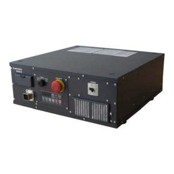
3 Force Sense Function System Specifications 3.2 System Configuration The device configuration required to use the force sense function is shown below. Force sense interface unit (2F-TZ561) Serial cable between unit and sensor (2F-FSCBL1-05) 24 VDC output cable (2F-PWRCBL-01) Force sensor 24 VDC power (1F-FS001-W200) supply... -
Page 16: Force Sense Function Specifications
3 Force Sense Function System Specifications 3.3 Force Sense Function Specifications The force sense function specifications are as follows. Table 3-1: Force sense function specifications Item Function Details Applicable robot RV-F Series / RH-F Series Robot program language MELFA-BASIC V (with dedicated force sense function commands) Force Stiffness control Function used to control robot softly (Sets stiffness coefficients,... -
Page 17: Force Sense Interface Unit Specifications
3 Force Sense Function System Specifications 3.4 Force Sense Interface Unit Specifications The force sense interface unit specifications are as follows. Table 3-2: Force sense interface unit specifications Item Unit Specification Value Remarks Model 2F-TZ561 Force No. of connected sensors sensor sensors Interface... -
Page 18: Name Of Each Force Sense Interface Unit Part
3 Force Sense Function System Specifications Name of Each Force Sense Interface Unit Part 3.4.2 The name of each force sense interface unit part is as follows. CN4 connector (not used) CN1A CN9 connector (for robot controller (not used) connection) DC24 connector CN1B CN422... -
Page 19: Vdc Power Supply Outline Drawing
3 Force Sense Function System Specifications 24 VDC Power Supply Outline Drawing 3.4.5 Fig. 3-3: 24 VDC power supply outline drawing Force Sense Interface Unit Specifications 3-9... -
Page 20: Force Sensor Specifications
3 Force Sense Function System Specifications 3.5 Force Sensor Specifications The force sensor specifications are as follows. Table 3-3: Force sensor specifications Item Unit Specification Value Remarks Model 1F-FS001-W200 Fx, Fy, Fz Rated load Mx, My, Fx, Fy, Fz 1000 Max. -
Page 21: Force Sensor External Dimensions
3 Force Sense Function System Specifications Force Sensor External Dimensions 3.5.1 Outline drawings of the force sensor are shown below. H7, effective depth 4 H7, effective depth 4 (Detection axis Y) (Y-) (Y-) Positioning pin hole Positioning pin hole 2 -3 H7, depth 4 2 -3 H7, depth 4 (Detection axis X) -
Page 22: Coordinate System Definition
3 Force Sense Function System Specifications 3.6 Coordinate System Definition The force and moment coordinate systems used with the force sense function are summarized in "Table 3-4". Table 3-4: Force sense coordinate system list Coordinate System Name Description Force sense coordinate system Coordinate system that forms reference for calibration (mechanical interface) (See section... -
Page 23: Force Sense Coordinate System (Mechanical Interface)
3 Force Sense Function System Specifications Force Sense Coordinate System (Mechanical Interface) 3.6.1 The force sense coordinate system (mechanical interface) is defined as follows. +FXm +MXm +FZm +MZm Mechanical interface coordinate Force sense coordinate system system +MYm * Refer to the separate "Detailed (mechanical interface) Explanations of Functions and Operations (BFP-A8586)"... -
Page 24: Force Sense Coordinate System (Xyz)
3 Force Sense Function System Specifications Force Sense Coordinate System (XYZ) 3.6.3 The assumed force sense coordinate system (XYZ) used in force sense function processing is defined as follows. XYZ coordinate system (direction only) * Refer to the separate "Detailed Explanations of Functions and Operations (BFP-A8586)"... -
Page 25: Force Sensor Coordinate System
3 Force Sense Function System Specifications Force Sensor Coordinate System 3.6.4 The force sensor coordinate system is defined as follows. +FYs Robot side +MYs Tool side +MXs +FXs +FZs +MZs Coordinate Left-hand system system origin point 18 mm The origin point of the force sensor coordinate system is the position 18 mm away from the robot side surface. -
Page 26: Check Before Use
4 Check Before Use 4 Check Before Use 4.1 Product Check The standard configuration of this product is as follows. Please check. Table 4-1: Force sensor set product configuration list Part Name Model Quantity Force sensor 4F-FS001-W200 1F-FS001-W200 (force sensor set) Force sense interface unit 2F-TZ561 Sensor attachment adapter (RV-2/4/7F) -
Page 27: Software Versions
4 Check Before Use 4.2 Software Versions All software must support the force sense function to facilitate its use. Check all versions prior to use. ■ Robot controller Part Name Model Applicable Version Controller CR750-Q/CR751-Q Ver.R3m or later CR750-D/CR751-D Ver.S3m or later ■... -
Page 28: Attaching The Force Sensor
5 Attaching the Force Sensor 5 Attaching the Force Sensor This Chapter describes how to attach the force sensor. The force sensor is a precision measuring instrument, and attaching it carelessly may lead to a drop in accuracy or fault. Always check the following before performing attachment. -
Page 29: Recommended Attachment Angle
5 Attaching the Force Sensor The bolts should also be tightened a little at a time to ensure an even attachment surface when attaching a hand to the force sensor tool side (Tightening torque: 6 N·m). Care should also be taken with regard to the following points. If not attached properly, it will not be possible to obtain force data accurately, leading to a drop in force sense control performance. -
Page 30: Device Connection, Wiring, And Settings
6 Device Connection, Wiring, and Settings 6 Device Connection, Wiring, and Settings This Chapter describes "force sensor", "force sense interface unit", and "robot controller" connection, as well as default parameter settings. 6.1 Force Sense Unit Robot Controller Connect the force sense interface unit and robot controller as shown below. CR750-D controller <CR750-D Series>... - Page 31 6 Device Connection, Wiring, and Settings <CR751-D Series> CR751-D controller (front side) Connect to ExtOPT connector. SSCNET III cable When using additional MR-J3-B axis functions CN1A SSCNET III cable SSCNET III cable CN1B Force sense interface unit 2F-TZ561 (front side) * If using the additional axis function, connect a general-purpose servo Connect to amp after the force sense interface unit.
- Page 32 6 Device Connection, Wiring, and Settings <CR750-Q/CR751-Q Series> Connect to ExtOPT connector. SSCNET III cable CN2 connector When using additional MR-J3-B axis functions CN1A SSCNET III cable SSCNET III cable CN1B Force sense interface unit 2F-TZ561 (front side) * If using the additional axis function, connect a general-purpose servo Connect to <Pin amp after the force sense interface unit.
-
Page 33: Force Sense Interface Unit Force Sensor
6 Device Connection, Wiring, and Settings 6.2 Force Sense Interface Unit Force Sensor Connect the force sense interface unit and force sensor as shown below. <Robot with internal wiring> Force sense I/F Built-in cable unit Force sensor Connect to CN422 connector. -
Page 34: Turning On The Power
6 Device Connection, Wiring, and Settings 6.3 Turning ON the Power Turn ON the power only after checking that the force sense interface unit, robot controller, and force sensor have been properly connected. Turn the power ON and OFF in the following order. <When turning the power ON>... -
Page 35: Default Parameter Settings
6 Device Connection, Wiring, and Settings 6.4 Default Parameter Settings Set the following parameters after turning ON the power. (Settings can be specified efficiently using the RT ToolBox2 / R56TB / R57TB parameter setting screen. See section 12.2 12.3 After setting all parameters, reboot the controller. -
Page 36: Force Sense Interface Unit Identification
6 Device Connection, Wiring, and Settings Force Sense Interface Unit identification 6.4.1 It is necessary to set parameters at the robot controller side in order for the robot controller to recognize the force sense interface unit. Set these parameters as follows. (The same parameters as that for the additional axis function are used.) Parameter Parameter... -
Page 37: Calibration
6 Device Connection, Wiring, and Settings Calibration 6.4.2 To use the force sense function, it is necessary to define (calibrate) the correlation between the force sensor coordinate system and force sense coordinate system (mechanical interface). Calibration is performed with the following parameter settings. - Page 38 6 Device Connection, Wiring, and Settings 6.4.2.1 Parameter Setting Example 1 (for Recommended Attachment) When the force sensor attachment is the recommended attachment (described in section the parameter settings for elements 1 to 4 for FSHAND and FSXTL will be the default factory settings. Change only elements 1 to 3 for FSXTL.
- Page 39 6 Device Connection, Wiring, and Settings 6.4.2.2 Parameter Setting Example 2 If, as shown below, the force sensor coordinate system origin is offset 50 mm in the +Zm direction and rotated 30 degrees around the Zm-axis as viewed from the mechanical interface coordinate system, set the parameters as follows.
-
Page 40: Force Sensor Tolerance
6 Device Connection, Wiring, and Settings Force Sensor Tolerance 6.4.3 The system is equipped with a function to stop robot operation in order to protect the force sensor if a value greater than that set for force and moment in parameter FSLMTMX is detected. Always set parameter FSLMTMX before use. -
Page 41: Force Sensor Control Offset Limit
6 Device Connection, Wiring, and Settings Force Sensor Control Offset Limit 6.4.4 This parameter sets the position command offset upper limit for force sense control. If the offset exceeds this upper limit, an error (H2760) occurs. This acts as a protection function for inadequate operation or setting, and therefore the required minimum value should be set. -
Page 42: Checking The Connection And Settings
7 Checking the Connection and Settings 7 Checking the Connection and Settings Before using the force sense function, ensure that force sensor data is being sent to the robot controller in the correct coordinate system. 7.1 Checking Force Sensor Data Communication Display the teaching pendant force sense control screen with the following operation, and ensure that the force sensor data is displayed correctly. -
Page 43: If Using R32Tb/R33Tb
7 Checking the Connection and Settings If Using R32TB/R33TB 7.1.2 Menu screen Extension function menu screen Monitor mode Ensure that the force sensor data changes. Checking Force Sensor Data Communication 7-33... -
Page 44: Checking The Force Sensor Attachment Coordinate System
7 Checking the Connection and Settings 7.2 Checking the Force Sensor Attachment Coordinate System Check force data when external force is applied by hand to the force sensor tool side. If set correctly, the correlation between the direction in which force is applied and the changed direction in the force data will be as shown in "Table 7-1". -
Page 45: Using The Force Sense Function (Programming)
8 Using the Force Sense Function (Programming) 8 Using the Force Sense Function (Programming) This Chapter describes robot programming using the force sense function. The force sense function consists of "force sense control", "force sense detection", and "force sense log" functions. -
Page 46: Force Sense Control
8 Using the Force Sense Function (Programming) 8.1 Force Sense Control The force sense control function is used to control robot softness and push force. Depending on the application, this function switches between "force control" and "stiffness control". The characteristics of each type of control are described below. - Page 47 8 Using the Force Sense Function (Programming) Singular point adjacent operation restrictions Singular point adjacent operation cannot be performed while force sense control is enabled, 注意 regardless of interpolation or JOG operation. If the robot approaches a point adjacent to a singular point during operation, an error (L3986) occurs.
-
Page 48: Force Sense Enable/Disable Commands
8 Using the Force Sense Function (Programming) Force Sense Enable/Disable Commands 8.1.1 Force sense control is started with the MELFA-BASIC V language Fsc On command based on conditions specified for arguments "Control mode", "Control characteristics ", and "Offset cancel command". (Refer to "Chapter for details on operation from the teaching pendant.) Force sense control is disabled with the Fsc Off command. -
Page 49: Control Mode / Control Characteristics
8 Using the Force Sense Function (Programming) Control Mode / Control characteristics 8.1.2 When enabling force sense control, it is necessary to specify conditions for starting force sense control. Table Table 8-3 shows a list of setting items relating to force sense control conditions. Table 8-3: Force sense control conditions Setting Item Description... - Page 50 8 Using the Force Sense Function (Programming) Force Sets the force command for force sense control. (See FSFCMD0# P_FsFCd0 command section 8.1.2.5 P_FsFCd1 value [Setting range]: - force sensor tolerance value to + force sensor tolerance value [Setting unit]: X, Y, Z component = N A, B, C component = N·m (This setting is not required for axes for which force control is not selected.)
- Page 51 8 Using the Force Sense Function (Programming) All parameter settings are classified by "condition groups" consisting of the control mode and control characteristics, and "condition Nos." constituting numbers -1 to 9. When specifying conditions with the Fsc On command, they are specified with a combination of these "condition groups" and "condition Nos." Statement structure:FscOn, <Control mode>, <Control characteristics >, <Offset cancel designation>...
- Page 52 8 Using the Force Sense Function (Programming) 8.1.2.1 Force Sense Control Coordinate System The coordinate systems used with force sense control are specified from the following. Tool coordinate system XYZ coordinate system Force sense coordinate system (tool) Force sense coordinate system (XYZ) +FXt +FZt +FYt...
- Page 53 8 Using the Force Sense Function (Programming) 8.1.2.3 Stiffness Coefficient Stiffness control softness is specified with the stiffness coefficient. The stiffness coefficient is the equivalent of spring constant, and the greater the value, the harder the control. <Correlation between teaching position and reaction force> If stiffness control mode is selected, when an external force acts on the arm tip, resulting in displacement between the teach position and actual position, the robot moves to a position at which the reaction force corresponding to the "displacement"...
- Page 54 8 Using the Force Sense Function (Programming) 8.1.2.5 Force Command Value Sets the force command value for force control (force priority mode). When force control is enabled, the robot moves so that the reaction force specified with the force command value can be obtained. If no external force acts on the robot (if no contact is made), the robot moves in the force command value direction and reaction force direction (direction in which the specified force is produced when contact is made.) +FXt...
- Page 55 8 Using the Force Sense Function (Programming) The speed specified with the speed command value is the force sense control offset Caution speed, and not the actual robot movement speed. If the robot is not moving in other than in force sense control, such as when performing interpolation commands or JOG operation, but moving only in speed priority mode, the "specified offset speed = robot movement speed".
- Page 56 8 Using the Force Sense Function (Programming) <Force priority mode> Data from the force sensor is used to control the robot until the force specified with the force specification value is reached. The robot moves in the direction which satisfies the force specification value by following the axis direction for which force control is specified.
-
Page 57: Offset Cancel Designation
8 Using the Force Sense Function (Programming) 8.1.2.9 Force Detection Setting Value The force detection setting value is used with the following functions. Refer to the respective items. Function Class Description Reference Force sense Interrupt Monitors the status with regard to the force See section detection execution... -
Page 58: Control Characteristics Change Commands
8 Using the Force Sense Function (Programming) Control characteristics Change Commands 8.1.4 The "control characteristics " (force sense control gain, force specification value, speed command value, mode switching judgment value, force detection setting value) settings can be changed while force sense control is enabled using the MELFA-BASIC V language FsGChg and FsCTrg commands. - Page 59 8 Using the Force Sense Function (Programming) FsCTrg (FsC trigger) [Function] Sets the control feature change for force sense control with an Mo trigger. * If using the FsCTrg command, it is necessary to set the Mo trigger conditions beforehand. [Syntax] FsCTrg ...
-
Page 60: Usage Example (Force Sense Control)
8 Using the Force Sense Function (Programming) Usage Example (Force Sense Control) 8.1.5 This section describes the specific usage method for each function using sample programs. <Control mode / control characteristics settings> The sample programs described below set the "control mode" and "control characteristics " using status variables. - Page 61 8 Using the Force Sense Function (Programming) Force Control 1 ■ Operation details The robot is pushed in the Z-direction with a force of 10 N. Force control is started from the PStart position. The robot is moved in the force sense control coordinate system (tool) +FZt direction until a reaction force of 10 N can be obtained.
- Page 62 8 Using the Force Sense Function (Programming) Force Control 2 (Force-Speed Priority Mode Switching) ■ Operation details The robot is moved at a speed of 5 mm/s in the tool Z-direction and pushed with a force of 10 N the moment it collides.
- Page 63 8 Using the Force Sense Function (Programming) ■ Description Force sense control is started with the Fsc On command based on the conditions set for "Control mode (0)" and "Control characteristics (0)". If the external force is less than the "mode switching judgment value (FZt=2.5N)" specified with the status variable P_FsSwF0, "speed priority mode"...
- Page 64 8 Using the Force Sense Function (Programming) Stiffness Control ■ Operation details Controls the robot softly like a spring with respect to external force applied in the force sense coordinate system (tool) ±FXt and ±FYt directions. Stiffness control is specified only for the FXt and Fyt axes. (Position control is specified for all other axes.) ...
- Page 65 8 Using the Force Sense Function (Programming) Control control characteristics Change 1 ■ Operation details The push force (control characteristics) is changed during robot movement. The robot starts moving from P1 to P2 while pushing with a force of 5.0 N in the Z-direction. ...
- Page 66 8 Using the Force Sense Function (Programming) ■ Description After the robot moves to the position 3 mm over the contact position, wait for 1 s until the robot comes to a complete stop. Force sense control (force control) is started with the Fsc On command. The control characteristics change conditions are specified with the FsGChg command.
- Page 67 8 Using the Force Sense Function (Programming) Control characteristics Change 2 (Mo Trigger) ■ Operation details The robot moves while following a guide gauge. Movement is started in the +Y-direction at a speed of 10 mm/s while pushing in the –X direction with a force of 5 N.
- Page 68 8 Using the Force Sense Function (Programming) ■ Description Changes the control characteristics (force command direction, speed command when in speed priority mode) when the conditions specified for the Mo trigger are established using the FsCTrg command. (See section 8.2.1 for details on the Mo trigger.) The Mo trigger is defined with the Def MoTrg command.
-
Page 69: Force Sense Detection
8 Using the Force Sense Function (Programming) 8.2 Force Sense Detection The force sense detection function detects the robot contact status using force sensor information. By using this function, applications with high degree of freedom can be constructed in MELFA-BASIC V to detect contact during movement, change the movement direction, detect work failures, and perform retry operation or error processing and so on. -
Page 70: Mo Trigger
8 Using the Force Sense Function (Programming) Mo Trigger 8.2.1 The Mo trigger function is used to issue trigger signals when conditions are established based on conditions defined by combining the following data with a comparison operation. The Mo trigger status is output to status variable M_MoTrg. - Page 71 8 Using the Force Sense Function (Programming) Refer to " Chapter Language Specifications " for details on each command. Def MoTrg (Def Mo trigger) [Function] Defines trigger conditions (Mo trigger) that reference position commands and the FB position, as well as force sensor data and so on.
- Page 72 8 Using the Force Sense Function (Programming) M_MoTrg [Function] References the Mo trigger enabled/disabled status, and the enabled trigger ON/OFF status. [Syntax] Example) <Numerical variable> = M_MoTrg (<Trigger No.>) Details Value Defined/Undefined Enabled/Disabled Trigger ON/OFF Status Status Status Defined Enabled Defined Enabled ――...
-
Page 73: Force Detection Status
8 Using the Force Sense Function (Programming) Force Detection Status 8.2.2 8.2.2.1 M_FsLmtS Status variable M_FsLmtSw checks whether the force detection setting value specified with the " control characteristics " group has been exceeded. It can be used for interrupt processing and so on when a collision occurs. - Page 74 8 Using the Force Sense Function (Programming) (Refer to section 11.3 for details on status variables.) 8-64 Force Sense Detection...
- Page 75 8 Using the Force Sense Function (Programming) Usage Example (Force Sense Detection) 8.2.5 Interrupt Processing (M_FsLmtS) ■ Operation details Abnormal force is detected at times of collision and the robot comes to an emergency stop. The force detection status is constantly monitored, and when contact is made, the robot is stopped swiftly and interrupt processing is executed.
- Page 76 8 Using the Force Sense Function (Programming) and interrupt processing can be performed when a contact judgment/work failure occurs. Interrupt Processing (Mo Trigger) ■ Operation details The push force and position are inspected simultaneously, and the quality of the work is judged. ...
- Page 77 8 Using the Force Sense Function (Programming) P2.Z=P2.Z+100 'Target position determined as position +100 mm in Z-direction from current position Mvs P2 ■ Description Work complete conditions are defined for Mo trigger 1 with the Def MoTrg command. Force sense control is enabled after enabling Mo trigger 1, and insertion work is started. If insertion work is not complete within 5 seconds of work starting, a 9100 error is output, and insertion work is stopped.
- Page 78 8 Using the Force Sense Function (Programming) Data Latch/Data Referencing ■ Operation details Position data and force data during push movement is latched, and the spring part spring constant is calculated. Data is set to that position and force data is saved at the point FZt=10 N is exceeded. (Data latch function) ...
- Page 79 8 Using the Force Sense Function (Programming) ■ Description The force detection setting value is set and force control is enabled so that the position/force data are latched when FZt=10 N. The robot is moved slowly to position PEnd at the speed of 10 mm/s and the spring is pushed. Each of the position/force data at the moment the spring reaction force at the spring push process exceeds 10 N is saved to status variables P_FsLmtP and P_FsLmtD.
-
Page 80: Force Sense Log
8 Using the Force Sense Function (Programming) 8.3 Force Sense log The force sense log function is used to obtain and display log data such as force sensor data and position data. Log data can be viewed in a graph using the RT ToolBox2 force sense control log file viewer. This function can be used for such tasks as force sense control related parameter adjustments and checking the work status. - Page 81 8 Using the Force Sense Function (Programming) Table 8-11: Collected data Collected Data Unit Supplementary Information Set with parameter FSLOGFN from the following: Force sensor raw data (with offset cancel) Force sensor Force sensor raw data (without offset cancel) [N] or [Nm] data ...
-
Page 82: Parameter Settings
8 Using the Force Sense Function (Programming) Parameter Settings 8.3.2 Parameter settings relating to the force sense log function are as follows. It is necessary to set parameter FSLOGFN in order to use the force sense log function. (Settings can be specified efficiently using the parameter editing screen discussed in sections 12.2 12.3 Table 8-13: Force sense log related parameter list... -
Page 83: Force Sense Log Data Acquisition
8 Using the Force Sense Function (Programming) Force Sense Log Data Acquisition 8.3.3 Robot language MELFA-BASIC V FsLog On and FsLog Off commands are used to specify the start and end of log data acquisition. When the FsLog Off command is executed, a log file with specified file No. name is generated. -
Page 84: Force Sense Log Data Display (Rt Toolbox2)
8 Using the Force Sense Function (Programming) Force Sense Log Data Display (RT ToolBox2) 8.3.4 The method used to display force sense log data in a graph using the RT ToolBox2 force sense control log file viewer function is described below. 8.3.4.1 Start Method Select [Tools] ... - Page 85 8 Using the Force Sense Function (Programming) 8.3.4.2 Main Screen Log files are imported and displayed in a graph using the buttons on the force sense control log file viewer main screen. A description of each button is given below. Fig.
- Page 86 8 Using the Force Sense Function (Programming) Item Description By pressing the [Read RC] button and reading a log file with the [Copy File] check box selected, a log file save screen appears after reading the log file. Specify the file save destination and file name, and then click [OK] to save the read log file to the computer.
- Page 87 8 Using the Force Sense Function (Programming) 8.3.4.3 Data Selection Screen Selects data displayed at the following Data Selection screen. If separating the graph into Graph 1 and Graph 2, select the "Graph 2" check boxes for data to be displayed in Graph 2. Fig.
- Page 88 8 Using the Force Sense Function (Programming) 8.3.4.4 Display Range Setting Screen Sets the range for the displayed waveform data from the [Display Range] screen. Fig. 8-5 Image of Display Range setting screen Table 8-16 Display Range setting screen description Item Description Vertical axis display...
-
Page 89: Force Sense Log File Ftp Transfer
8 Using the Force Sense Function (Programming) Force Sense Log File FTP Transfer 8.3.5 Force sense log files created in the robot controller can be transferred to an FTP server using the robot language MELFA-BASIC V FsOutLog command. FsOutLog [Function] Transfers logged data to the FTP server. -
Page 90: Usage Example (Force Sense Log)
8 Using the Force Sense Function (Programming) Usage Example (Force Sense Log) 8.3.6 Force Sense Log Data Acquisition and Display ■ Operation details Acquires data for the force acting on the workpiece when performing assembly work and displays it in a graph. ... - Page 91 8 Using the Force Sense Function (Programming) ■ Description Specifies settings to push the robot with a force of 0.0 N in the X- and Y-directions, and 5.0 N in the Z-direction with force control. The FsLog On command is executed to start log data acquisition. Insertion work is started with the Fsc On command, and the robot pushes until a reaction force of 4.5 N or greater acts in the Z-direction.
- Page 92 8 Using the Force Sense Function (Programming) Force Sense Log Data Transfer ■ Operation details Transfers acquired log data files to the computer (FTP server). Force sense log data is collected during force sense control. Force sense log data is saved and saved log files are transferred to the computer. Force sense log file [1.fsl] og File Version,1.0 Time Stamp,YYYY.MM.DD HH:MM:SS...
-
Page 93: Using The Force Sense Function (Teaching)
9 Using the Force Sense Function (Teaching) 9 Using the Force Sense Function (Teaching) This Chapter describes how to use the force sense function (force sense T/B) using the teaching pendant, and how to perform teaching using the force sense function. Refer to the section numbers and pages under "Reference"... -
Page 94: Force Sense T/B
9 Using the Force Sense Function (Teaching) 9.1 Force Sense T/B The force sense functions that can be used from R56TB/R57TB/R32TB/R33TB are summarized in "Table 9-2". Table 9-2: Force sense functions that can be used from teaching pendant Force Item Function Overview Force sense Force control... - Page 95 9 Using the Force Sense Function (Teaching) 9.1.1.1 Offset Cancel Operation If the force sensor data zero point is offset, force sense control will not function properly. Always perform the offset cancel operation (sensor zero point offset) before use. The offset cancel operation can only be performed when force sense control is disabled.
- Page 96 9 Using the Force Sense Function (Teaching) 9.1.1.2 Selecting the Control Mode/Control characteristics Before enabling force sense control, it is necessary to set the force sense control "control mode" and "control characteristics " (parameters/status variables shown in Table 9-3) beforehand. (See section 8.1.2 for details.) Table 9-3: Control mode/Control characteristics settings...
- Page 97 9 Using the Force Sense Function (Teaching) 9.1.1.3 Force Sense Control Enable/Disable Selection Enable or disable force sense control. If performing JOG operation using force sense control, select "Enable", and if performing normal JOG operation, select "Disable". The enable/disable selection is common to both automatic operation and JOG operation. The enable/disable status is retained even if the controller key switch is changed to and from MANUAL and AUTOMATIC.
-
Page 98: Force Sense Monitor
9 Using the Force Sense Function (Teaching) Force Sense Monitor 9.1.2 Displays the force sensor current and maximum values. Retained maximum values can also be cleared. [Checking the force sensor data current/maximum values] The force sensor data current and maximum values are shown below. ... -
Page 99: Contact Detection
9 Using the Force Sense Function (Teaching) Contact Detection 9.1.3 If the force sense data exceeds the selected "control characteristics” force detection setting value while force sense control is enabled, JOG operation is automatically stopped. Furthermore, the buzzer sounds and the force sensor data display field on the teaching pendant changes color to notify the user that the force detection setting value has been exceeded. -
Page 100: Usage Example (Force Sense Function T/B)
9 Using the Force Sense Function (Teaching) Contact detection precautions When the robot is stopped by contact detection, the robot moves from the point the force is detected until the robot stops, and therefore a larger force than the force detection setting value may act. - Page 101 9 Using the Force Sense Function (Teaching) gain Force detection FSFLMT01 +0.00, +0.00, +0.00, +0.00, +0.00, +0.00 setting value (* In this example, settings are specified with parameters, however, setting is also possible with status variables.) (2) Offset cancel operation (See section 9.1.1.1 ...
- Page 102 9 Using the Force Sense Function (Teaching) (3) Control mode/control characteristics selection (See section 9.1.1.2 Set the "control mode" and "control characteristics” numbers. In this example, control mode 1 and control characteristics 1 are used, and therefore the settings are as follows. [R32TB/R33TB] (4) Force sense control enable operation (See section 9.1.1.3...
- Page 103 9 Using the Force Sense Function (Teaching) Contact Detection/Force Sense Monitor ■ Operation details JOG operation is stopped automatically if unnecessary force acts on the workpiece. Check the maximum value for force applied to the workpiece. JOG operation is stopped if unnecessary force is applied.
- Page 104 9 Using the Force Sense Function (Teaching) (4) Force sense control enable operation (See section 9.1.1.3 Turn the servo ON after enabling force sense control, and then use JOG operation to move the robot to the insertion complete position. ...
-
Page 105: Teaching Operation
9 Using the Force Sense Function (Teaching) 9.2 Teaching Operation This Chapter describe teaching operation using force sense control. Teaching operation precautions If using force sense control, the position displayed on the teaching pendant and the actual robot position will differ. - Page 106 9 Using the Force Sense Function (Teaching) <Method 1>…Perform teaching operation after disabling force sense control. By disabling force sense control, the "command position" changes to the "force sense position command". <Method 2>…Perform teaching operation after pressing the "Teach pos. search" [Execute] button. By pressing the "Teach pos.
- Page 107 9 Using the Force Sense Function (Teaching) (Example)..If inserting pins while following the workpiece shape with stiffness control (stiffness coefficient ≠ 0), external force acts on one side of the pin. By performing teaching position search" at such times, the robot can "...
-
Page 108: Usage Example (Teaching Operation)
9 Using the Force Sense Function (Teaching) Usage Example (Teaching Operation) 9.2.2 Teaching a Position Pushed with Fixed Force ■ Teaching details Teach the position at which the spring reaction force becomes 25 N. Teach this position. 25 N Spring ■... - Page 109 9 Using the Force Sense Function (Teaching) (5) Teaching (The following two teaching methods are available.) <Method 1> Ensure that the force sensor data is Fz=25 N, and then disable force sense control with the servo ON. (By disabling force sense control, the current position data appears on the teaching pendant.) ...
- Page 110 9 Using the Force Sense Function (Teaching) Teaching the Insertion Position (Using Force Control) ■ Teaching details Teach the ideal insertion position on which no external force acts. Operation procedure (1) Parameter settings Select all axes and force control, and set the force command so that the robot is pushed with a force of 5 N in the FZt direction, and external force is eliminated for all other axes.
- Page 111 9 Using the Force Sense Function (Teaching) Teaching the Insertion Position (Using Stiffness Control) Teaching details Teach the ideal insertion position on which no external force acts. Operation procedure (1) Parameter settings Specify force stiffness control for all axes until the robot becomes suitably soft. Control Force sense control FSCOD01...
-
Page 112: Force Sense Function Screen
9 Using the Force Sense Function (Teaching) 9.3 Force Sense Function Screen R56TB/R57TB 9.3.1 If using the force sensor, an [F] button appears in the bottom of the JOG screen. By pressing this button, a force sense control screen appears on the left of the JOG screen. Fig. - Page 113 9 Using the Force Sense Function (Teaching) Table 9-4: Screen overview Screen Control Overview [F] button Displays/hides a screen (surrounded by red box in Fig. 9-3) relating to force sense control. (Does not appear if the force sensor interface unit is not connected.) ...
- Page 114 9 Using the Force Sense Function (Teaching) Force Monitor Displays the force detection setting value (corresponds to parameters FSFLMT01 to 09 and status variables P_FsFLm0 and P_FsFlm1) specified at "Control characteristics " Screen Control Overview Current Displays the current force sensor data (corresponds to status variable P_FsCurD.) * Displays the value converted to the force sense coordinate system (Tool/XYZ).
-
Page 115: R32Tb/R33Tb
9 Using the Force Sense Function (Teaching) R32TB/R33TB 9.3.2 Force sense function related screens are displayed by selecting from the extension function menu screen or by changing function from the JOG screen. These screens appear as follows on the R32TB. [JOG] key Menu screen [JOG] key... - Page 116 9 Using the Force Sense Function (Teaching) Table 9-5: Screen overview Screen Name Overview Force sense control <Detection mode> top screen The screen changes by pressing the [FUNCTION] key. Detection mode is enabled when changing from the JOG operation screen. ...
- Page 117 9 Using the Force Sense Function (Teaching) Force detection setting value screen Screen Display Meaning "Fx" - "Mz" Displays the current force detection setting value specified with the control characteristics. Function Description [F4] Close Changes to the force sense control top screen. Conditions setting screen Screen Display...
- Page 118 9 Using the Force Sense Function (Teaching) Cancel confirmation screen Function Description Cancels the force sensor offset component. If the sensor data is not 0 with no external force acting on the sensor, it is necessary to perform offset cancel. [F1] Yes (* Operation rights required.) An error occurs when force sense control is enabled and the servo is...
-
Page 119: Application Examples
10 Application Examples 10 Application Examples Part Assembly Work (Force Control) Operation details Assembles parts so that no unnecessary force acts on the parts when following the part fitting shape. The robot is controlled using force control so that the force acting in the X- and Y- directions is 0.0 N. ... - Page 120 10 Application Examples ■Description With force control, the robot is set to push with a force of 0.0 N in the X- and Y-directions, and 5.0 N in the Z-direction. Furthermore, if the reaction force in the Z-direction is less than 4 N, the robot moves at a speed of 10 mm/s in speed priority mode.
- Page 121 10 Application Examples Phase Focusing Push Operation details The robot inserts into a metal axis while searching for a d-cut gear phase. The robot rotates in the C-axis direction while pushing softly in the Z-direction with robot stiffness softened by stiffness control.
- Page 122 10 Application Examples Description The robot is set to control the X-, Y-, Z-, and C-axes softly with stiffness control. The force detection setting value is Mz = 0.05 N·m. Force control is enabled, and the robot moves to a position approximately 1 mm below of the insertion start position.
-
Page 123: Language Specifications
11 Language Specifications 11 Language Specifications This Chapter describes specifications for force sense control function related to MELFA-BASIC V commands and status variables. Precautions when using status variables By directly referencing P variable A-, B-, and C-axis values as component data, they are read as radian unit values. - Page 124 11 Language Specifications Fsc On [Function] Enables the force sense control function using force sensor. [Syntax] FscOn <Control mode>, <Control characteristics >, <Offset cancel designation> [Terminology] <Control mode> Specifies the force sense control mode No. (See section 8.1.2 Setting range: -1 - 9 Table 11-2 Control mode setting items and corresponding values Control Mode Setting Item...
- Page 125 11 Language Specifications [Description] (1) Enables the force sense control function using force sensor. (Default: Disabled) (2) The force sense control content is specified with the "control mode" and "control characteristics " condition Nos. set beforehand. (3) If the force sensor is not connected and this command is executed, error L3986 occurs. (4) This command cannot be executed when the force sense control function is enabled (error L3987 occurs.) If changing the "control mode"...
- Page 126 11 Language Specifications Table 11-4 Behavior with simultaneous used with force sense control function Function Behavior with Simultaneous Use Error Compliance control Priority is given to the function enabled first. L3986 (Cmp command) Collision detection Priority is given to the force sense control function. L3986 (ColChk command) If force sense control function is enabled while collision...
- Page 127 11 Language Specifications Fsc Off [Function] Disables the force sense control function using force sensor. [Syntax] FscOff [Example] Refer to examples in section 11.7 [Description] (1) Disables the force sense control function using force sensor. (2) If the force sensor is not connected, no processing is performed when this command is executed. (3) Similarly, no processing is performed when this command is executed while the force sense control function is disabled.
- Page 128 11 Language Specifications FsGChg (Fs gain change) [Function] Changes control characteristics for force sense control during operation. [Syntax] FsGChg <Change start time>, <Change time>, <Control characteristics group No. after change> [Terminology] <Change start time> Specifies the position at which the control characteristics setting change is started. This is specified with an interrupt during the next interpolation command start point and end point.
- Page 129 11 Language Specifications FcCTrg (FsC trigger) [Function] Sets force sense control characteristics switching with the Mo trigger. [Syntax] FsCtrg <Trigger No.>, <Change time>, <Control characteristics group No. after change> [, <Timeout>,<Execution method> [, <Error specification>]] [Terminology] <Trigger No.> Specifies the Mo trigger No. used to change the control characteristics with a constant. Setting range: 1 - 3 <Change time>...
- Page 130 11 Language Specifications control characteristics change is not completed within the specified time. (Error L.3987) (8) If program execution is interrupted, the timeout processing count up is also interrupted. If program execution is resumed, the timeout processing count up is also resumed. (9) If program execution is interrupted, the timeout processing count up is also interrupted.
-
Page 131: Status Variables Relating To Force Sense Control Function
11 Language Specifications 11.2 Status Variables Relating to Force Sense Control Function This section describes MELFA-BASIC V status variables relating to the force sense control function. Table 11-5 Force sense control status variables Status Variable Function Overview M_FsCod0, Specifies/references the force sense control coordinate M_FsCod1 system. - Page 132 11 Language Specifications M_FsCod0, M_FsCod1 [Function] Specifies/references the force sense control coordinate system. [Syntax] Example) M_FsCod0=<Numeric variable 1> Example) <Numeric variable 2>=M_FsCod1 [Terminology] <Numeric variable 1> Specifies the force sense control coordinate system. Setting Mode Coordinate system (Tool) Coordinate system (XYZ) <Numeric variable 2>...
- Page 133 11 Language Specifications P_FsMod0, P_FsMod1 [Function] Specifies/references the force sense control mode for each axis. [Syntax] Example) P_FsMod0=<Position variable 1> Example) <Position variable 2>=P_FsMod1 [Terminology] <Position variable 1> Specifies the force sense control mode for each axis. Setting Mode Position control Force control Stiffness control <Position variable 2>...
- Page 134 11 Language Specifications P_FsStf0, P_FsStf1 [Function] Specifies/references the stiffness coefficient for force sense control (stiffness control). [Syntax] Example) P_FsStf0=<Position variable 1> Example) <Position variable 2>=P_FsStf1 [Terminology] <Position variable 1> Specifies the stiffness coefficient for force sense control (stiffness control). (The L1- and L2-axis components do not use this variable.) Component Setting Range Unit...
- Page 135 11 Language Specifications P_FsDmp0, P_FsDmp1 [Function] Specifies/references the damping coefficient (responsiveness) for force sense control (stiffness control/force control). [Syntax] Example) P_FsDmp0=<Position variable 1> Example) <Position variable 2>=P_FsDmp1 [Terminology] <Position variable 1> Specifies the damping coefficient for force sense control. (The L1- and L2-axis components do not use this variable.) Component Setting Range Unit...
- Page 136 11 Language Specifications P_FsFCd0, P_FsFCd1 [Function] Specifies/references the force command value for force sense control (force control). [Syntax] Example) P_FsFCd0=<Position variable 1> Example) <Position variable 2>=P_FsFCd1 [Terminology] <Position variable 1> Specifies the force command value for force sense control (force control). (The L1- and L2-axis components do not use this variable.) Component Setting Range...
- Page 137 11 Language Specifications P_FsSpd0, P_FsSpd1 [Function] Specifies/references the speed command value for force sense control (force control). [Syntax] Example) P_FsSpd0=<Position variable 1> Example) <Position variable 2>=P_FsSpd1 [Terminology] <Position variable 1> Specifies the speed command value for force sense control (force control). (The L1- and L2-axis components do not use this variable.) Component Setting Range...
- Page 138 11 Language Specifications P_FsSwF0, P_FsSwF1 [Function] Specifies/references the force priority mode/speed priority mode switching judgment value for the force sense function (force control). [Syntax] Example) P_FsSwF0=<Position variable 1> Example) <Position variable 2>=P_FsSwF0 [Terminology] <Position variable 1> Specifies the force control mode/speed control mode switching judgment value for force sense control (force control).
- Page 139 11 Language Specifications P_FsGn0, P_FsGn1 [Function] Specifies/references the force sense control gain (responsiveness) for the force sense function. [Syntax] Example) P_FsGn0=<Position variable 1> Example) <Position variable 2>=P_FsGn1 [Terminology] <Position variable 1> Specifies the force sense control gain for force sense control. (The L1- and L2-axis components do not use this variable.) Component Setting Range...
- Page 140 11 Language Specifications P_FsFLm0, P_FsFLm1 [Function] Specifies/references the force sensor force detection setting value for the force sense function. [Syntax] Example) P_FsFLm0=<Position variable 1> Example) <Position variable 2>=P_FsFLm1 [Terminology] <Position variable 1> Specifies the force sensor force detection setting value. (The L1- and L2-axis components do not use this variable.) Component Setting Range...
-
Page 141: Commands Relating To Force Sense Detection Function
11 Language Specifications 11.3 Commands Relating to Force Sense Detection Function This section describes MELFA-BASIC V commands relating to the force sense detection function (Mo trigger function). Table 11-6 Mo trigger commands Command Function Overview Def MoTrg Defines trigger conditions (Mo trigger) that reference position commands and the FB position, as well as force sensor data and so on. - Page 142 11 Language Specifications [Example] 1 Def MoTrg 1, ((P_Fbc.Z <= 100) Or (P_FsCurD.Z >= 10)) And (P_FsCurP.C < -45DEG) ' Defines the ON trigger as Mo trigger No.1 by satisfying the following conditions (1) and (2). ' (1) FB position Z-axis value is 100 mm or less, or Z-axis direction force sensor data is 10 N or greater.
- Page 143 11 Language Specifications SetMoTrg (Set Mo trigger) [Function] Enables/disables trigger conditions (Mo trigger) that reference position commands and the FB position, as well as force sensor data and so on. [Syntax] SetMoTrg <Trigger No.> [Terminology] <Trigger No.> Specifies the trigger No. for the Mo trigger to be enabled with a constant. If 0 is specified, the Mo.
-
Page 144: Status Variables Relating Force Sense Detection Function
11 Language Specifications 11.4 Status Variables Relating Force Sense Detection Function This section describes MELFA-BASIC V status variables relating to the force sense detection function. Table 11-7 Force sensor function related status variables Status Function Overview Class Variable M_MoTrg Checks the Mo trigger enabled/disabled status and the Mo trigger trigger ON/OFF status while enabled. - Page 145 11 Language Specifications M_MoTrg [Function] Checks the Mo trigger enabled/disabled status and the trigger ON/OFF status while enabled. [Syntax] Example) <Numerical variable>= M_MoTrg (<Trigger No.>) [Terminology] <Trigger No.> Specifies the Mo trigger No. being checked with a constant. Setting range: 1 - 3 <Numerical variable>...
- Page 146 11 Language Specifications M_FsLmtS [Function] Checks whether the force sensor data force detection setting value has been exceeded. [Syntax] Example) <Numerical variable>= M_FsLmtS [Terminology] <Numerical variable> Specifies the read numerical variable for determining whether the force detection setting value has been exceeded.
- Page 147 11 Language Specifications P_FsLmtR [Function] Checks the status of the current force sensor data with respect to the force sensor data force detection setting value. [Syntax] Example) <Position variable>= P_FsLmtR [Terminology] <Position variable> Specifies the substitute position variable. [Example] Refer to examples in section 11.7 [Description] (1) Displays where the current force sensor data lies in the status shown in the following diagram with respect...
- Page 148 11 Language Specifications P_FsLmtX [Function] Checks/resets axes for which the force sensor data force detection setting value is exceeded. [Syntax] Example) <Position variable>= P_FsLmtX Example) P_FsLmtX =<Position variable> [Terminology] <Position variable> Specifies the substitute position variable. [Example] Refer to examples in section 11.7 [Description] (1) Displays whether the force sensor data's absolute value has exceeded the force detection setting value.
- Page 149 11 Language Specifications P_FsLmtP [Function] Checks/resets the robot FB position when the force sensor data force detection setting value is exceeded. [Syntax] Example) <Position variable>= P_FsLmtP Example) P_FsLmtP =<Position variable> [Terminology] <Position variable> Specifies the substitute position variable. [Example] Refer to examples in section 11.7 [Description] (1) Checks robot position feedback when the force sensor data's absolute value exceeds the force detection...
- Page 150 11 Language Specifications P_FsLmtD [Function] Checks/resets the force sensor data when the force sensor data force detection setting value is exceeded. [Syntax] Example) <Position variable>= P_FsLmtD Example) P_FsLmtD =<Position variable> [Terminology] <Position variable> Specifies the substitute position variable. [Example] 300 If P_FsLmtX.X=1 Then P_FsFLmt.X=P_FsLmtD.X * 0.8 'If X-direction sensor data exceeds the force detection setting value: '80% of the exceeded value is set as the new force detection setting value.
- Page 151 11 Language Specifications P_FsMaxD [Function] Checks/resets the force sensor maximum data value during force sense control. [Syntax] Example) <Position variable>= P_FsMaxD Example) P_FsMaxD =<Position variable> [Terminology] <Position variable> Specifies the substitute position variable. [Example] 1000 P1=P_FsMaxD 'In P1, retains maximum force sensor data value up to this point. 1010 P_FsMaxD=P1 'Resets the maximum value.
- Page 152 11 Language Specifications P_FsCurD [Function] Checks the current force sensor data. [Syntax] Example) <Position variable>= P_FsCurD [Terminology] <Position variable> Specifies the substitute position variable. [Example] 100 Def Act 1, P_FsCurD.Z > 10 GoTo *INTR1, S 'If the Z-direction sensor data exceeds 10 N, an interrupt used to perform interrupt processing *INTR1 is defined.
- Page 153 11 Language Specifications P_FsCurP [Function] Checks the position (force sense position command) offset with force sense control. (Force sense position command = Position command calculated with movement command, etc. + position offset with force sense control) [Syntax] Example) <Position variable>= P_FsCurP [Terminology] <Position variable>...
- Page 154 11 Language Specifications M_FsCSts [Function] Checks the force sense control enabled/disabled status. [Syntax] Example) <Numerical variable>= M_FsCSts [Terminology] <Numerical variable> Specifies the substitute numerical variable. (1: Force sense control enabled, 0: Force sense control disabled) [Example] 2000 If M_FsCSts=1 Then Fsc Off 'Disables force sense control if enabled.
-
Page 155: Commands Relating To Force Sense Log Function
11 Language Specifications 11.5 Commands Relating to Force Sense Log Function This section describes MELFA-BASIC V status variables relating to the log function. Table 11-8: Log function commands Command Function Overview FsLog On Starts force sensor data and position command, position FB, and current FB value logging. - Page 156 11 Language Specifications FsLog Off [Function] Ends force sensor data and position command, position FB, and current FB value logging. [Syntax] FsLogOff <Log File No.> [Terminology] <Log File No.> Specifies the log file No. containing collected data. Setting range: 1 to 999999999 [Example] Refer to examples in section 11.7...
- Page 157 11 Language Specifications FsOutLog [Function] Transfers logged data to the FTP server. [Syntax] FsOutLog <Log File No.> [Terminology] <<Log File No.> Specifies the No. of the log file from which collected data is to be read. Setting range: 1 to 999999999 [Example] Refer to examples in section 11.7...
-
Page 158: Other Related Commands
11 Language Specifications 11.6 Other Related Commands Def Act [Function] Defines the interrupt conditions and processing for interrupt processing. Interrupts are used when input signals and so on are monitored while running programs to prioritize certain processing when the specified conditions are reached * "F"... - Page 159 11 Language Specifications * Additional axes decelerate to a stop in the same manner as that for Stop type 2 (S), regardless of whether force sense control is enabled or disabled. * If stopped with a Force sense stop (F), force sense control is disabled (including servo OFF), or position offset with force sense control is fixed at the stopped status until the interrupt is prohibited with "Act <Priority No.>=0".
- Page 160 11 Language Specifications command. (11) It is not possible to describe a condition format combined with a log operator such as in (M1 And &H001) = (12) If an interrupt is entered while performing perfect circle interpolation or circular interpolation (Mvc, Mvr, Mvr2, Mvr3) and control is returned to the original step with Return 0, the robot returns to the perfect circle or circular interpolation start point before once again performing circular or arc interpolation.
- Page 161 11 Language Specifications Conceptual drawings of each stop type for the execution program when interrupt conditions are established during robot movement are shown below. Stop Type External Override 100% (Max. Speed) External Override 50% Stop type 1 Speed Speed Interrupt (Omission) S1 = S2 Interrupt...
-
Page 162: Examples
11 Language Specifications 11.7 Examples Several force sense control program examples are shown below. Example 1 Sample Program FB01.prg The robot searches for the target object while moving in the Y-axis direction. When the object is found, the robot moves in the X-axis direction while applying a constant force in the target object Y-direction. - Page 163 11 Language Specifications Example 2 Sample Program FB02.prg Performs the insertion movement in the Z-axis direction with the X/Y-direction softened. An error occurs and movement is interrupted if a force greater than the specified value is applied when inserting. N ユ...
- Page 164 11 Language Specifications Example 3 Sample Program FB03.prg Searches for open holes on the XY plane. If a hole is found, the XY coordinates for the holes center position are calculated. 方向 動作し Robot moves in XY-direction and 接触位置 calculates center position from contact position.
- Page 165 11 Language Specifications PX(2)=P0 PY(1)=P0 PY(2)=P0 PX(1).X=P0.X+10 'The position ±10 mm in the XY-direction from the reference position is calculated. PX(2).X=P0.X-10 PY(1).Y=P0.Y+10 PY(2).Y=P0.Y-10 Fsc Off P_FsFLm0=(+2.00,+2.00,+5.00,+5.00,+5.00,+5.00)(0,0) 'Changes the X,Y-axis direction force detection setting value to 2 [N]. Fsc On,0,0,1 MFLG=0 For M1=1 To 2 Mvs PX(M1) WthIf P_FsLmtR.X=1,Skip 'Moves ±10 mm in the X-axis direction and skips if the force detection setting is exceeded.
- Page 166 11 Language Specifications Example 4 Sample Program FB04.prg The robot moves at the specified speed in the Z-direction to make contact with the target object. If the Z-axis direction robot position and force sensor data satisfy the specified conditions following contact, the robot starts moving in the Y-axis direction while pushing in the Z-axis direction.
-
Page 167: Parameter Specifications
12 Parameter Specifications 12 Parameter Specifications This Chapter describes parameters relating to the force sense function. 12.1 Force Sense Function Related Parameter List Table 12-1 Force sense control related parameters Parameter No. of Factory Default Parameter Description Name Elements Setting Force sense AXJNO 16 integers... - Page 168 12 Parameter Specifications Parameter No. of Factory Default Parameter Description Name Elements Setting Force sense FSCORM 2 real Sets the maximum position offset for force sense control. 10.0, 10.0 control offset numbers 1st element: Position maximum offset [mm] limit 2nd element: Posture maximum offset [deg.] [Setting range] 1st element: 0 to +200.0 2nd element: 0 to +150.0...
- Page 169 12 Parameter Specifications Parameter No. of Factory Default Parameter Description Name Elements Setting Control FSFGN01 8 real 0.0, 0.0, 0.0, Sets the force sense control gain (response sensitivity) characteristics - 09 numbers 0.0, 0.0, 0.0, for force sense control. (See section 8.1.2.8 0.0, 0.0 [Setting range]: 0.0 - 300.0...
-
Page 170: Rt Toolbox2 Force Sense Function Parameter Setting Screen
12 Parameter Specifications 12.2 RT ToolBox2 Force Sense Function Parameter Setting Screen (1) Force sensor settings This screen is used to set the force sense control function default parameters. It is necessary to reboot the controller after setting parameters. Fig. 12-1: Force sensor setting screen (2) Force control mode This screen is used to set the control mode for force sense control. - Page 171 12 Parameter Specifications (3) Force control characteristics This screen is used to set the control characteristics for force sense control. Parameter settings are updated immediately, and therefore there is no need to reboot the controller. [Force condition] tab [Speed condition] tab Fig.
- Page 172 12 Parameter Specifications (4) Force log setting This screen is used to set parameters for the force sense log function. It is necessary to reboot the controller after writing parameters. Fig. 12-4: Force log setting screen 12-162 RT ToolBox2 Force Sense Function Parameter Setting Screen...
-
Page 173: R56Tb/R57Tb Force Sense Function Parameter Setting Screen
12 Parameter Specifications 12.3 R56TB/R57TB Force Sense Function Parameter Setting Screen (1) Initial settings This screen is used to set the force sense control function default parameters. It is necessary to reboot the controller after setting parameters. Fig. 12-5: Force sense control Initial setting screen (2) Force control mode This screen is used to set the control mode for force sense control. - Page 174 12 Parameter Specifications (3) Force control characteristics This screen is used to set the control characteristics for force sense control. Parameter settings are updated immediately, and therefore there is no need to reboot the controller. [Mode switch judgment/Speed reference] button [Gain/Instruction/Detection] button Fig.
- Page 175 12 Parameter Specifications (4) Force log setting This screen is used to set parameters for the force sense log function. It is necessary to reboot the controller after writing parameters. Fig. 12-8: Force log setting screen R56TB/R57TB Force Sense Function Parameter Setting Screen 12-165...
-
Page 176: Troubleshooting
13 Troubleshooting 13 Troubleshooting 13.1 Behavior when Force Sense Control Errors Occur If any of the following types of error occurs, force sense control is disabled and the servo turns OFF. Table 13-1: Behavior when force sense control error occurs Error Type Error Details... - Page 177 13 Troubleshooting Table 13-2 Error List Error No. Error Details L_1864_00000 The FTP communication parameters are incorrect. L_2750_01000 Unable to disable force sense control while tracking. H_2760_00000 The force sense control offset value was approaching the limit value. () H_2770_00000 The force sense control offset position is outside the movement range.
-
Page 178: Force Control Function Related Error Details
13 Troubleshooting 13.3 Force Control Function Related Error Details (The power must be reset for errors with * in the Error No. "First 4 Digits" field.) Error No. Error Cause and Remedy First 4 Last 5 Digits Digits L1864 00000 Err. - Page 179 13 Troubleshooting L.3870 22000 Err. message The mechanical No. specified with the Def MoTrg command is an invalid value. Cause The mechanical No. specified with the Def MoTrg command is an invalid value. Remedy Set a correct mechanical No. L.3986 01n00 Err.
- Page 180 13 Troubleshooting Error No. Error Cause and Remedy First 4 Last 5 Digits Digits L.3986 16n00 Err. message Unable to perform offset cancel. (Force sense control) n=Mech. Cause It is not possible to perform offset cancel while the force sense control function is enabled.
- Page 181 13 Troubleshooting Error No. Error Cause and Remedy First 4 Last 5 Digits Digits L.3987 30n00 Err. message Unable to execute the FsCTrg command. n=Mech. Cause The Mo trigger for the FsCTrg command executed first is enabled. characteristics Remedy Execute after changing the control L.3987 characteristics 31n00...
- Page 182 13 Troubleshooting Table 13-3: Force sense interface unit errors Error No. (Name) Cause Remedy Force sense interface unit internal part fault Replace the unit. 12 (memory error) 13 (S/W processing error) 21 (sensor initial (1) The force sensor connection cable is (1) Connect the cable.
-
Page 183: Appendix
14 Appendix 14 Appendix 14.1 Control Status Transition Force sense control has the following 4 statuses. Status Description Force sense This is the force sense control disabled status. This is the status when the power is turned status disabled In this status, force sense control is enabled and the robot position is being offset based on Offsetting the "control mode"... - Page 184 14 Appendix Force sense control enabled Stop input/emergency stop input Error (H level/L level) Operation interrupted Fsc ON command Enabling of force sense with T/B Offsetting Offsetting stopped Power ON Force sense control disabled Start point input ...
- Page 186 O c t . . 2 0 1 2 M E E P r i n t e d i n J a p a n o n r e c y c l e d p a p e r . S p e c i f i c a t i o n s a r e s u b j e c t t o c h a n g e w i t h o u t n o t i c e .