Table of Contents
Advertisement
Advertisement
Table of Contents

Related Manuals for Lenovo 46M4002

Summary of Contents for Lenovo 46M4002
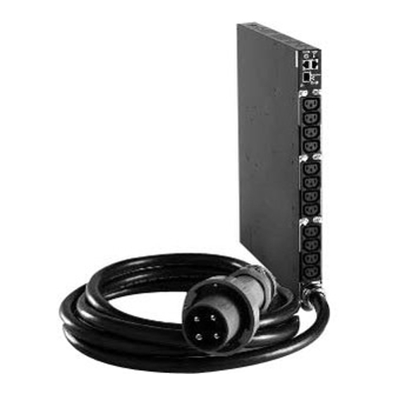
- Page 1 1U C19 and C13 Switched and Monitored PDUs Installation and Maintenance Guide...
- Page 2 Note: Before using this information and the product it supports, read the general information in Appendix D “Notices” on page 67; the safety information, warranties, and licenses information on the Lenovo Web site at: https://support.lenovo.com/documents/LNVO-DOCS Second Edition (October 2018) © Copyright Lenovo 2015, 2018.
-
Page 3: Table Of Contents
People's Republic of China Class A electronic emission statement ... Features....© Copyright Lenovo 2015, 2018... - Page 4 Index ....75 Taiwan Class A compliance statement ..Taiwan BSMI RoHS declaration ..1U C19 and C13 Switched and Monitored PDUs Installation and Maintenance Guide...
-
Page 5: Safety
Safety Before installing this product, read the Safety Information. Antes de instalar este produto, leia as Informações de Segurança. Læs sikkerhedsforskrifterne, før du installerer dette produkt. Lees voordat u dit product installeert eerst de veiligheidsvoorschriften. Ennen kuin asennat tämän tuotteen, lue turvaohjeet kohdasta Safety Information. Avant d'installer ce produit, lisez les consignes de sécurité. - Page 6 Les sikkerhetsinformasjonen (Safety Information) før du installerer dette produktet. Antes de instalar este produto, leia as Informações sobre Segurança. Antes de instalar este producto, lea la información de seguridad. Läs säkerhetsinformationen innan du installerar den här produkten. Each caution and danger statement in this documentation is labeled with a number. This number is used to cross reference an English-language caution or danger statement with translated versions of the caution or danger statement in the Safety Information document.
- Page 7 DANGER Electrical current from power, telephone, and communication cables is hazardous. To avoid a shock hazard: • Do not connect or disconnect any cables or perform installation, maintenance, or reconfiguration of this product during an electrical storm. • Connect all power cords to a properly wired and grounded electrical outlet. •...
- Page 8 Statement 14 CAUTION: Hazardous voltage, current, and energy levels might be present. Only a qualified service technician is authorized to remove the covers where the following label is attached.
-
Page 9: Chapter 1. Introduction
The following PDU models are available: • 46M4002 - 1U 9 C19 / 3 C13 Switched and Monitored DPI PDU (with removable power cord) • 46M4003 - 1U 9 C19 / 3 C13 Switched and Monitored 60 A 3 Phase PDU (with attached power cord) •... -
Page 10: Installation Requirements
• Danger: These statements indicate situations that can be potentially lethal or extremely hazardous to you. A danger statement is placed just before the description of a potentially lethal or extremely hazardous procedure step or situation. Installation requirements You will need the following tools to install the PDU in a rack cabinet: •... -
Page 11: Parts That Come With The 1U Pdu Models
1. Power cables for devices that you will connect to the PDU do not come with the PDU. 2. You will have some unused parts depending on how you install the PDU. Parts that come with the 1U PDU models The following parts come with the 1U PDU models: •... -
Page 12: Features Of The Pdu
• Two adjustable mounting rails (for horizontal mounting in all rack cabinets) Note: The following illustration shows the two components of one adjustable mounting rail. The adjustable mounting rail might come pre-assembled. • One 1U blank filler panel • Cable straps Features of the PDU The PDU models have the following features: •... -
Page 13: Hardware Components
Hardware components The following sections provide descriptions of the front and rear components on the PDUs. Front view The following illustration shows the components and controls on the front of the 1U PDU with 12 C13 outlets on the front. Circuit breakers Environment sensor connector... -
Page 14: Rear View
Input power connector Connect a power cord to this connector. Note: Some PDU models come with an attached power cord. Power outlets You can connect a device to each power outlet. Depending on the PDU model, there are C19 power outlets and C13 power outlets. -
Page 15: Pdu Load Groups
PDU load groups The PDU load groups are described in the following tables. Table 1. Switched and monitored 1U C19 PDU load groups Phase (when using 3- phase input power) Circuit breaker number Associated front outlet Associated rear outlet Table 2. Switched and monitored 1U C13 PDU load groups Associated outlets (The load segment number that is visible on the front of the PDU is in... - Page 16 Phase 1 Phase 2 Phase 3 outlet group 1 outlet group 2 outlet group 3 1112 The PDU models with 9 C19 outlets on the front have phase one connected to the first three (3) outlets, outlet group one. Phase 2 is connected to the next three (3) outlets, outlet group two. Phase 3 is connected to the last 3 outlets, outlet group three (see the following illustration).
-
Page 17: Chapter 2. Installing The 1U Pdu Vertically In A Rack Cabinet
Note: Removing the rack doors and side panels might make installation easier. See the rack cabinet documentation for more information. © Copyright Lenovo 2015, 2018... - Page 18 Review the documentation that comes with your rack cabinet for safety and cabling information. When you install the PDU in a rack cabinet, observe the following precautions: • Make sure that the room air temperature is below 35°C (95°F). • Do not block any air vents; usually 15 cm (6 in.) of air space provides proper airflow. •...
- Page 19 a. Leave enough space to connect, route, and disconnect power cords. b. If you are installing a cable-management bracket in the same side of the rack cabinet, leave enough space between the outlet side of the PDU and the EIA mounting flanges for the cable-management bracket installation.
-
Page 20: Installing The Pdu In The Side Of An Enterprise Rack Cabinet Only
Key alignment Twist lock 4. Route the power cord from the PDU toward the rack cabinet side braces; then, route the power cord along a side brace toward the back of the rack cabinet, and secure the power cord with the cable straps that come with the PDU. - Page 21 To install the PDU in the 1U mounting space in the side of an Enterprise rack cabinet, complete the following steps: 1. Align the vertical-mounting brackets to the front of the PDU. Be sure to attach the brackets so that the power outlets face the rear of the rack cabinet.
- Page 22 Attention: You must disconnect the main input power before you connect or disconnect the input power cord from the PDU. 4. If the PDU comes with a detached power cord, connect the power cord. Align the connector on the power cord that comes with the PDU with the connector on the front of the PDU, turning as necessary for key alignment;...
- Page 23 5. Route the power cord from the PDU toward the rack cabinet side braces; then, route the power cord along a side brace toward the back of the rack cabinet, and secure the power cord with the cable straps that come with the PDU. 6.
- Page 24 1U C19 and C13 Switched and Monitored PDUs Installation and Maintenance Guide...
-
Page 25: Chapter 3. Installing The 1U Pdu Horizontally In A Rack Cabinet
Use cage nuts for rack cabinets with square holes, and use clip nuts for rack cabinets with round holes. If your rack cabinet requires cage nuts, use a cage-nut-insertion tool or a flat-blade screwdriver to install them. Cage nuts Clip nuts Cage nuts Statement 1 © Copyright Lenovo 2015, 2018... - Page 26 DANGER Electrical current from power, telephone, and communication cables is hazardous. To avoid a shock hazard: • Do not connect or disconnect any cables or perform installation, maintenance, or reconfiguration of this product during an electrical storm. • Connect all power cords to a properly wired and grounded electrical outlet. •...
- Page 27 a. Align the two parts of the adjustable mounting rail as shown in the following illustration. Adjustable mounting rail b. Secure the two adjustable mounting rail parts with three screws that come with the rack-mounting kit. 3. Align the adjustable mounting rails with the holes in the side rear of the PDU and attach the mounting rails to the PDU with three M3 pan-head screws with captive lock washers per rail.
- Page 28 6. Secure the adjustable mounting rails and the 1U blank filler panel to the rack cabinet. Blank filler panel a. Install a cage nut or clip nut in the applicable hole in the rack flange on each side of the rack cabinet. b.
- Page 29 Key alignment Twist lock 8. Route the power cord from the PDU toward the rack cabinet side braces; then, route the power cord along a side brace toward the back of the rack cabinet, and secure the power cord with the cable straps that come with the PDU.
- Page 30 1U C19 and C13 Switched and Monitored PDUs Installation and Maintenance Guide...
-
Page 31: Chapter 4. Cabling The Pdu
3. Connect the DB9-to-RJ-45 cable that comes with the PDU to the RJ-45 console connector on the PDU, as shown in the previous illustration. 4. Connect the DB9 connector end of the converter cable to the cable that you connected to the PDU in step 3 on page 23. © Copyright Lenovo 2015, 2018... -
Page 32: Connecting To A Lan
5. Connect the USB connector end of the converter cable to the workstation or notebook computer. Communication is now established with the PDU through the COM port that is created by the converter cable. For information about initially setting up the PDU and to configure PDU settings, see “Using the PDU Configuration Utility to set up the PDU”... -
Page 33: Connecting Output Devices
PDU environment sensor Ethernet cable Environment sensor connector For more information about the environment sensor, see Chapter 6 “Using the PDU environment sensor” on page 49. Connecting output devices The PDU power outlets are for connecting devices such as workstations, servers, and printers. You can monitor the power status of a connected device either manually or remotely through the RS-232 and Ethernet connectors. - Page 34 1U C19 and C13 Switched and Monitored PDUs Installation and Maintenance Guide...
-
Page 35: Chapter 5. Monitoring The Power Status
Click OK. The Connect To window opens. Step 3. From the Connect using list, select the COM port that is connected to the PDU. Click OK. The Properties window opens. © Copyright Lenovo 2015, 2018... - Page 36 Step 4. Select 115200 from the Bits per second list and select None from the Flow control list. Click OK. Step 5. When a blank window opens, press Enter. The PDU Configuration Utility login window opens. Type the default login ID ADMIN and the password 1001. Press Enter. The PDU Configuration Utility Step 6.
- Page 37 On the main menu window, press 2 to set up the network parameters. The Setup Network Step 7. Information window opens. To enable or disable DHCP, press either 1 or 2 as applicable. The default is Disable. Then, type the Step 8.
- Page 38 Press 1 to view the PDU default configuration information. A window similar to the one in the Step 9. following illustration is displayed. Step 10. Press any key to return to the main menu. You can continue to use the PDU Configuration Utility, or you can use the web interface to configure and monitor the PDU remotely.
-
Page 39: Power-On Sequencing (Some Models)
Power-on sequencing (some models) You can use the power-on sequence function to define a sequence for powering on the PDU outlets. You can use Telnet and SNMP through the Ethernet port or HyperTerminal through the serial port to configure the power-on sequence function. - Page 40 • IndividualDelayTimer (range: from 0 - 3600 seconds; data type: integer). Each outlet also has its own individual delay variable (IndividualDelayTimer) that is accessible through either a serial (HyperTerminal) or Ethernet (Telnet and SNMP) interface. If IndividualDelayTimer is not set (equal to 0), the individual outlet delay function is not enabled.
-
Page 41: Using Hyperterminal Through The Serial Port
Outlet 10 2 Sec Outlet 11 5 Sec Outlet 12 3 Sec The following table shows the PDU outlet power-on timing when power is restored after a power outage. Table 3. Power-on timing Outlet power-on Outlet timing number Comment 16th second Total Delay time =bootup time + GlobalDelayTimer + IndividualDelayTimer 17th second Total Delay time =bootup time + GlobalDelayTimer + IndividualDelayTimer... - Page 42 On the PDU Configuration Utility main menu, type 8 to select Set PDU Location and Outlet Step 3. Information. Step 4. Ttype the GlobalDelayTimer value. 1U C19 and C13 Switched and Monitored PDUs Installation and Maintenance Guide...
-
Page 43: Using Telnet Through The Ethernet Port
Step 5. On the main menu, type the IndividualDelayTimer values for each outlet. Using Telnet through the Ethernet port To set the parameters for the power-on sequence function by using an Ethernet port and the Telnet interface, complete the following steps: Step 1. - Page 44 Type 1 for System Configuration. Step 2. Type 3 for Outlet Global Delay Timer and PDU Location. Step 3. Type 15 to define the Outlet Global Delay Timer. Step 4. 1U C19 and C13 Switched and Monitored PDUs Installation and Maintenance Guide...
- Page 45 Step 5. Type the value for the New Outlet Global Delay Timer. Type 0 to return to the previous menu. Step 6. Type 4 for the Outlet Name and Individual Delay Timer. Step 7. Chapter 5 Monitoring the power status...
-
Page 46: Using Snmp Through The Ethernet Port
Step 8. Type the outlet number and enter the outlet name and its IndividualDelayTimer value. Using SNMP through the Ethernet port To set the parameters for the power-on sequence function by using an Ethernet port and the SNMP interface, complete the following steps: 1U C19 and C13 Switched and Monitored PDUs Installation and Maintenance Guide... -
Page 47: Using The Web Interface
For the latest MIB file, go to http://www.ibm.com/support/fixcentral/ Step 1. Set the GlobalDelayTimer parameter with the object identifier (OID) as shown in the following illustration. Step 2. Set the IndividualDelayTimer parameter with the OID. Using the web interface This section provides information about using the web interface to configure and monitor the PDU remotely. The PDU provides a graphical user interface that you can view from a web browser. -
Page 48: Starting The Web Interface
Starting the web interface To start the web interface, complete the following steps: Step 1. Start a web browser from a workstation or notebook computer and enter the IP address of the PDU in the address field. The Login window opens. In the User Name field, type ADMIN (all uppercase letters). -
Page 49: Power Management Relay Setting
Power management relay setting You can use the power management relay setting to turn each power outlet on or off by using the software. On the Setting of Relay page, you can change the relay setting. For the load segment and relay of the power outlet for which you want to turn on or off, click Set to turn off the outlet or click Set again to turn on the outlet. -
Page 50: Modifying The Basic Settings
Modifying the basic settings Use the System menu to configure the PDU system parameters such as the system name, IP address, date, and time. Some of these settings are described in the following sections. Changing the system information On the Configuration of PDU page, you can change the system name and location, SNMP community, and history log interval, and you can restart the PDU. - Page 51 Identifying the PDU On the Identification of Power Management page, you can view the PDU information such as the part number, serial number, and MAC address. Note: You cannot modify the information on the Identification of Power Management page. Changing the date and time On the Date and Time page, you can change the date and time of the PDU.
- Page 52 Changing event alerts If an event occurs within the PDU that triggers a trap, the trap information can be sent to a monitoring application through SNMP. On the SNMP Trap Receivers page, you can specify the IP address of a server on which a monitoring application is running.
- Page 53 Import configuration You can import the configuration settings for the PDU on the Import Configuration page. The import function updates the EEPROM of the PDU. Export configuration On the Export Configuration page, you can export the configuration settings of the PDU to a file. Then, you can import the exported file to other like PDUs in the network to provide consistent and similar configuration settings.
-
Page 54: Changing The Network Configuration
Changing the network configuration You can view or change the network configuration of the PDU on the Network Configuration page. You can set the PDU IP address, gateway address, subnet mask, TFTP server address, mail server address, and SMTP port number. You can also set up the e-mail receivers table to list two users who are alerted with an e- mail. - Page 55 Viewing the history log On the History Log page, you can access the complete history of the PDU inputs, outputs, and PDU environment sensor. On the page, you can clear the history log or export the history log to a comma- separated values (CSV) file.
- Page 56 1U C19 and C13 Switched and Monitored PDUs Installation and Maintenance Guide...
-
Page 57: Chapter 6. Using The Pdu Environment Sensor
• When temperature and humidity values exceed user-selectable limits, the event is logged in the PDU event history log. Connecting the PDU environment sensor to the PDU To connect the PDU environment sensor to the PDU, complete the following steps: © Copyright Lenovo 2015, 2018... - Page 58 1. If applicable, connect external contact inputs to the screw terminals on the PDU environment sensor. Pin 1 PDU environment sensor screw terminals Note: External contact device 1 is connected between pins 1 and 2. Device 2 is connected between pins 3 and 4 (as labeled to show device 1 and 2).
- Page 59 Status. The Status of Environment Sensor page opens. The temperature and humidity status is automatically displayed. 5. Click Environment, and then click Configuration. The Configuration of Environment Sensor page opens. You can set the upper and lower ranges of temperature and humidity that will generate SNMP traps and e-mail notification, if the PDU is configured to do so.
- Page 60 1U C19 and C13 Switched and Monitored PDUs Installation and Maintenance Guide...
-
Page 61: Chapter 7. Customer Replaceable Unit Parts
Tier 1 CRU at your request, you will be charged for the installation. • Tier 2 customer replaceable unit: You may install a Tier 2 CRU yourself or request Lenovo to install it, at no additional charge, under the type of warranty service that is designated for your server. - Page 62 1U C19 and C13 Switched and Monitored PDUs Installation and Maintenance Guide...
-
Page 63: Chapter 8. Pdu Specifications
DPI 32 amp / 250 V single-phase 1U 9 C19 / 3 C13 switched and monitored DPI PDU with IEC 309 P+N+Gnd connector (46M4002; 40K9612)Note: Special connector for Australia and New Zealand (not IEC 309): (46M4002; 40K9617) DPI 60 amp / 208 V single-phase 1U 9 C19 / 3 C13 switched and monitored DPI PDU with IEC 309 2P+Gnd connector (46M4002;... - Page 64 Weight(not including power cord) 6.3 kg (13.8 lb) Weight of power cord (approximate, varies by PDU model) 5.4 kg (11.8 lb) Operating temperature at 0 - 914 m (0 - 3000 ft)(room ambient) 10°C - 60°C (50°F - 140°F) Operating temperature at 914 -2133 m (3000 - 7000 ft) (room 10°C - 60°C (50°F - 140°F) ambient) Operating humidity...
- Page 65 PDU description Plug Rating Outlet DPI 32 amp / 250 V three- 32 amps, 250 V ac IEC 309 3P phase Enterprise C19 / C13 +N+Gnd PDU+ (or PDU) with IEC 309 3P+N+Gnd connector DPI 32 amp / 250 V single- 32 amps, 250 V ac IEC 309 P phase Enterprise C19 / C13 +N+Gnd...
- Page 66 PDU description Plug Rating Outlet DPI 60 amp / 208 V three- 48 amps, 250 V ac IEC 309 3P phase Enterprise C19 / C13 +Gnd PDU+ (or PDU) with IEC 309 3P+Gnd connector DPI 32 amp / 250 V single- 32 amps, 250 V acP/N phase Enterprise C19 / C13 56S0332P+N+Gnd...
-
Page 67: Appendix A. Default Pdu Settings
The default IPv4 IP address of the 1U C19 and C13 Switched and Monitored PDU is 192.168.1.254 with a subnet mask of 255.255.255.0. The default PDU administrator logon user name is ADMIN (in capitals) and the default password is 1001. They are also referred to as default user account credentials. © Copyright Lenovo 2015, 2018... - Page 68 1U C19 and C13 Switched and Monitored PDUs Installation and Maintenance Guide...
-
Page 69: Appendix B. Behavior Of The Pdu Reset Button
• Press and hold the reset button for two to five seconds: reset the PDU to the default user account credentials. See Appendix A “Default PDU settings” on page 59. • Press and hold the reset button for more than eight seconds: restart the system. © Copyright Lenovo 2015, 2018... - Page 70 1U C19 and C13 Switched and Monitored PDUs Installation and Maintenance Guide...
-
Page 71: Appendix C. Getting Help And Technical Assistance
Before you call, make sure that you have taken these steps to try to solve the problem yourself. If you believe that you require warranty service for your Lenovo product, the service technicians will be able to assist you more efficiently if you prepare before you call. -
Page 72: Using The Documentation
• Secure upload with the system serial number: https://www.ecurep.ibm.com/ app/upload_hw Creating a personalized support web page You can create a personalized support web page by identifying Lenovo products that are of interest to you. 1U C19 and C13 Switched and Monitored PDUs Installation and Maintenance Guide... -
Page 73: Software Service And Support
IBM is Lenovo's preferred service provider for the System x, Flex System and NeXtScale System products. You can receive hardware service through your Lenovo reseller or from IBM. To locate a reseller authorized by Lenovo to provide warranty service, go to and click Business Partner http://www.ibm.com/partnerworld... - Page 74 1U C19 and C13 Switched and Monitored PDUs Installation and Maintenance Guide...
-
Page 75: Appendix D. Notices
Lenovo representative for information on the products and services currently available in your area. Any reference to a Lenovo product, program, or service is not intended to state or imply that only that Lenovo product, program, or service may be used. Any functionally equivalent product, program, or service that does not infringe any Lenovo intellectual property right may be used instead. -
Page 76: Trademarks
Lenovo encourages owners of information technology (IT) equipment to responsibly recycle their equipment when it is no longer needed. Lenovo offers a variety of programs and services to assist equipment owners in recycling their IT products. For information on recycling Lenovo products, go to: http://www.lenovo.com/... -
Page 77: Particulate Contamination
If Lenovo determines that the levels of particulates or gases in your environment have caused damage to the device, Lenovo may condition provision of repair or replacement of devices or parts on implementation of appropriate remedial measures to mitigate such environmental contamination. -
Page 78: Federal Communications Commission (Fcc) Statement
Properly shielded and grounded cables and connectors must be used in order to meet FCC emission limits. Lenovo is not responsible for any radio or television interference caused by using other than recommended cables and connectors or by unauthorized changes or modifications to this equipment. Unauthorized changes or modifications could void the user's authority to operate the equipment. -
Page 79: Japanese Electromagnetic Compatibility Statements
Verträglichkeit von Geräten), bzw. der EMV EU Richtlinie 2014/30/EU, für Geräte der Klasse A. Dieses Gerät ist berechtigt, in Übereinstimmung mit dem Deutschen EMVG das EG-Konformitätszeichen - CE - zu führen. Verantwortlich für die Konformitätserklärung nach Paragraf 5 des EMVG ist die Lenovo (Deutschland) GmbH, Meitnerstr. 9, D-70563 Stuttgart. -
Page 80: Korea Communications Commission (Kcc) Statement
Japanese Electrical Appliance and Material Safety Law statement (for detachable AC power cord) JEITA harmonics guideline - Japanese Statement for AC power consumption (W) JEITA harmonics guideline - Japanese Statement of Compliance for Products Less than or Equal to 20A per phase JEITA harmonics guideline - Japanese Statement of Compliance for Products More than 20A Korea Communications Commission (KCC) statement This is electromagnetic wave compatibility equipment for business (Type A). -
Page 81: People's Republic Of China Class A Electronic Emission Statement
People's Republic of China Class A electronic emission statement Taiwan Class A compliance statement Appendix D. Notices... - Page 82 Taiwan BSMI RoHS declaration 1U C19 and C13 Switched and Monitored PDUs Installation and Maintenance Guide...
- Page 83 1U PDU models all PDU models connecting a PDU environment sensor hardware service and support telephone numbers connecting output devices help connecting the console from the World Wide Web connecting the power cord 11, 14 © Copyright Lenovo 2015, 2018...
- Page 84 connecting to a LAN using web interface CRU part numbers SNMP features using for power-on sequencing front view components and controls (1U) software service and support telephone numbers horizontal mounting in rack cabinet specifications, PDU installation requirements statements and notices load balancing support web page, custom load groups...