Advertisement
Quick Links
Operating Instructions
Included Installation Instructions
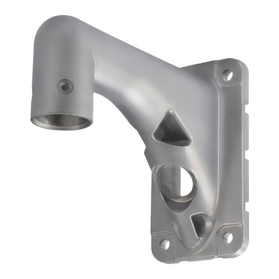
Wall Mount Bracket
WV-Q122A
Model No.
The camera in the illustration is separately sold.
Before attempting to connect or operate this product,
please read these instructions carefully and save this manual for future use.
The model number is abbreviated in some descriptions in this manual.
Advertisement

Related Manuals for Panasonic WV-Q122A


Summary of Contents for Panasonic WV-Q122A
- Page 1 Operating Instructions Included Installation Instructions Wall Mount Bracket WV-Q122A Model No. The camera in the illustration is separately sold. Before attempting to connect or operate this product, please read these instructions carefully and save this manual for future use. The model number is abbreviated in some descriptions in this manual.
-
Page 2: Table Of Contents
CONTENTS Preface ......................................3 Precautions ....................................3 Precautions for installation ................................4 Major operating controls ................................5 Installations/Connections ................................6 Specifications ..................................14 Standard accessories ................................14... -
Page 3: Preface
Preface This mount bracket is used for installing the color CCTV camera and network camera on a wall. Refer to the catalog or operating instructions of the camera for further information about the compatible models. Precautions Do not strike or give a strong shock to this product. Refer installation work to the dealer. -
Page 4: Precautions For Installation
Precautions for installation Panasonic assumes no responsibility for injuries or property damage resulting from failures arising out of improper installation or operation inconsistent with this documentation. The installation should comply with local electrical • Locations where radiation, x-ray, intense radio wave, or strong magnetism is produced code. -
Page 5: Major Operating Controls
Major operating controls Hexagonal screw hole for mounting camera (4 points) Camera mounting part Wire hook section Cable access hole (front) Plate Cable access hole (rear) -
Page 6: Installations/Connections
Installations/Connections Be sure to read "Precautions" and "Precautions for installation" before installation. Read the operating instructions for the camera to be installed as well. The Operating Instructions mainly describe for installing a network camera. The basic flow of the installation operation is the same as the one for the color CCTV camera. The flow of how to install the wall mount bracket is described as follows. - Page 7 Step 3 Remove the attachment pipe from the upper base by loos- ening 4 screws. Attachment pipe Go to "■ When laying cables through the cable access ☞ hole (front)" ( 8 page) or "■ When laying cables after drill- ☞...
- Page 8 [2] Attaching the mount bracket The installation of the wall mount bracket is roughly divided into 2 methods. Refer to the applicable description. ☞ ■ When laying cables through the cable access hole (front) ( 8 page) ☞ ■ When laying cables after drilling a hole through the wall ( 10 page) ■...
- Page 9 For the case of the camera with M6 screws being used: Step 7 Use the screws supplied with the bracket and a hexagonal Connect the cables to the camera. wrench "for M6". Connect the cables from the housing base with the cables (Recommended tightening torque (for common use in M5 on the wall.
- Page 10 ■ When laying cables after drilling a hole through the wall Step 2 Mount the cable cap (accessory) on the cable access hole Step 1 (front). Decide the mounting position, and drill a hole for a screw or an anchor and a hole for cable installation in the wall. Procure 4 pieces of M10 screws and anchors to secure the this bracket on the wall.
- Page 11 Step 5 Step 6 Lay the cables from the housing base via this blacket into Connect the cables to the camera. the slit cable cap. Connect the cables from the housing base with the cables Secure the housing base to the wall mount bracket. coming through the wall.
- Page 12 [3] Mounting of the camera body on the mount bracket Step 1 Step 2 For the case of color CCTV camera, peel off the seal on the Align the flat spring with the START position. top of the camera, and specify the communication method If not, rotate the plate on the top of the camera clockwise to and unit address using the DIP switches.
- Page 13 Step 4 Step 5 When attaching the camera to the housing base, the posi- Mount the front and rear sunshields, and then remove the tioning pin shall be on the "REAR" side. protection cover. Make sure that the camera is securely attached to the Refer to the Operating Instructions of the camera for further mount bracket by turning the bracket counterclockwise information.
-
Page 14: Specifications
Specifications Ambient operating temperature: –50 °C to +55 °C {–58 °F to 131 °F} Dimensions: 120 mm (W) x 220 mm (H) x 269 mm (D) {4-23/32 inches (W) x 8-21/32 inches (H) x 10-19/32 inches (D)} Mass: Approx. 2 kg {4.42 lbs} Finish: Aluminum die cast (coating color: fine silver (901)) Weight and dimensions indicated are approximate. - Page 16 For U.S. and Canada: For Europe and other countries: Panasonic Corporation Panasonic System Communications Company of North America, Unit of Panasonic Corporation of North America http://panasonic.net www.panasonic.com/business/ For customer support, call 1.800.528.6747 Importer's name and address to follow EU rules:...