Table of Contents

Related Manuals for IBM System x iDataPlex dx360


Summary of Contents for IBM System x iDataPlex dx360
- Page 1 System x iDataPlex dx360 Types 6313, 6316, 6385, 6390, 7831, and 7833 User's Guide...
- Page 3 System x iDataPlex dx360 Types 6313, 6316, 6385, 6390, 7831, and 7833 User's Guide...
- Page 4 Note: Before using this information and the product it supports, read the general information in Appendix B, “Notices,” on page 45 and the Warranty and Support Information document on the IBM Documentation CD. Fourth Edition (June 2011) © Copyright IBM Corporation 2011.
-
Page 5: Table Of Contents
Related documentation ..... . 2 The IBM Documentation CD ....3 Hardware and software requirements . - Page 6 Hardware service and support ....44 IBM Taiwan product service ....44 Appendix B.
-
Page 7: Safety
Les sikkerhetsinformasjonen (Safety Information) før du installerer dette produktet. Antes de instalar este produto, leia as Informações sobre Segurança. Antes de instalar este producto, lea la información de seguridad. Läs säkerhetsinformationen innan du installerar den här produkten. © Copyright IBM Corp. 2011... - Page 8 2. First, remove power cords from outlet. 3. Attach signal cables to connectors. 3. Remove signal cables from connectors. 4. Attach power cords to outlet. 4. Remove all cables from devices. 5. Turn device ON. IBM iDataPlex dx360 User's Guide...
- Page 9 Statement 2: CAUTION: When replacing the lithium battery, use only IBM Part Number 33F8354 or an equivalent type battery recommended by the manufacturer. If your system has a module containing a lithium battery, replace it only with the same module type made by the same manufacturer.
- Page 10 Hazardous voltage, current, and energy levels are present inside any component that has this label attached. There are no serviceable parts inside these components. If you suspect a problem with one of these parts, contact a service technician. viii IBM iDataPlex dx360 User's Guide...
- Page 11 Statement 10: CAUTION: Do not place any object on top of rack-mounted devices. Safety...
- Page 12 IBM iDataPlex dx360 User's Guide...
-
Page 13: Chapter 1. Introduction
This User's Guide contains general information about how to use, upgrade, and configure the components in the customized server solutions. These components consist of the IBM System x iDataPlex dx360 Type 6316, 6390, or 7833 system-board tray, the IBM System x iDataPlex Types 6313, 6385, or 7831 2U flex chassis, and the IBM System x iDataPlex storage enclosure. -
Page 14: Related Documentation
These updates are available from the IBM Systems Information Center. To check for updated iDataPlex information and technical updates, go to http://publib.boulder.ibm.com/infocenter/idataplx/documentation/index.jsp . The updated iDataPlex documentation also is available from the IBM Support Web site. To check for updated documentation and technical updates, complete the following steps. -
Page 15: The Ibm Documentation Cd
1. Go to http://www.ibm.com/systems/support/. 2. Under Product support, click System x. 3. Under Popular links, click Publications lookup. 4. From the Product family menu, select System x iDataPlex dx360 server and click Go. The IBM Documentation CD The IBM Documentation CD contains documentation in Portable Document Format (PDF) and includes the IBM Documentation Browser to help you find information quickly. -
Page 16: Notices And Statements In This Document
Notices and statements in this document The caution and danger statements in this document are also in the multilingual Safety Information document, which is on the IBM Documentation CD. Each statement is numbered for reference to the corresponding statement in your language in the Safety Information document. -
Page 17: Features And Specifications
Features and specifications The following information is a summary of the features and specifications of the hardware. Depending on the hardware configuration, some features might not be available, or some specifications might not apply. Racks are marked in vertical increments of 4.45 cm (1.75 inches). Each increment is referred to as a unit, or “U.”... -
Page 18: What Your Dx360 System-Board Tray Offers
– Hard disk drive health The diagnostic programs create a merged log that includes events from all collected logs. The information is collected into a file that you can send to IBM service and support. Additionally, you can view the information locally through a generated text report file. -
Page 19: Reliability, Availability, And Serviceability
v Redundant connection The system-board tray provides a failover capability to a redundant Ethernet connection. If a problem occurs with the primary Ethernet connection, all Ethernet traffic that is associated with the primary connection is automatically switched to the redundant NIC. If the applicable device drivers are installed, this switching occurs without data loss and without user intervention. -
Page 20: The Updatexpress Program
Note: To install the UpdateXpress program, you might need to use an external USB CD-RW/DVD drive such as the IBM and Lenovo part number 73P4515 or 73P4516. See “Firmware updates” on page 39 for additional instructions about using an external USB CD-RW/DVD drive. -
Page 21: Chapter 2. Components, Features, And Controls
(LEDs), and how to turn the system-board tray on and off. System-board tray components The following illustration shows the major components in the dx360 system-board tray. Note: The illustrations in this document might differ slightly from your hardware. © Copyright IBM Corp. 2011... -
Page 22: System-Board Connectors
See “Operator panel controls, LEDs, connectors, and power” on page 13 for information about the external connectors. See the Problem Determination and Service Guide for information about the other system-board connectors. IBM iDataPlex dx360 User's Guide... -
Page 23: System-Board Switches And Jumpers
System-board switches and jumpers The following illustration shows the locations of the jumpers on the system board that relate to selected system functions. See the Problem Determination and Service Guide for more information about using switches and jumpers on the system board. -
Page 24: Flexible Chassis Features
Flexible chassis features The following illustration shows an IBM System x iDataPlex 2U flex chassis. The 2U chassis contains a power supply and a fan assembly that provide operating power and cooling for all components in the chassis. The 2U chassis can support two system-board trays or one system-board tray with a storage enclosure. -
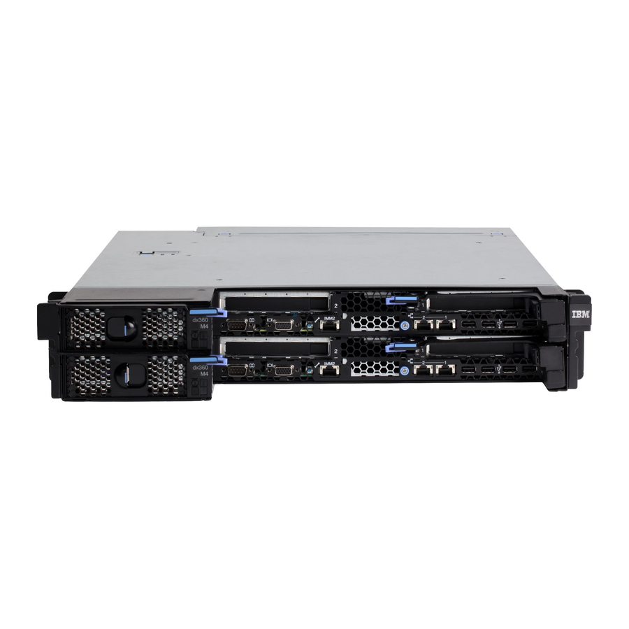
Page 25: 2U Compute Server
2U compute server The 2U compute server consists of two identical dx360 system-board trays installed in a 2U flex chassis. Each system-board tray has one PCIe adapter connector and one 3.5–inch hard disk drive bay. 2U storage server The 2U storage server consists of one dx360 system-board tray with the storage enclosure installed in a 2U flex chassis. - Page 26 Note: If this LED is off, it does not mean that no electrical power is present. The LED might be burned out. To remove all electrical power, you must disconnect the power cord from the chassis. IBM iDataPlex dx360 User's Guide...
-
Page 27: Rear Connectors
Rear connectors Power-cord connector: Connect the power cord to this connector. When the chassis is installed in an iDataPlex rack, it is connected automatically to power through a power cord that is mounted to the rack rail. Chapter 2. Components, features, and controls... -
Page 28: Turning On The System-Board Tray
– Through the management appliance control interface, you might also be able to configure the management appliance to turn off the system-board tray. For additional information, see the documentation for your management appliance. IBM iDataPlex dx360 User's Guide... -
Page 29: Chapter 3. Installing Optional Devices
(Orange can also indicate touch points on hot-swap components.) See the instructions for removing or installing a specific hot-swap component for any additional procedures that you might have to perform before you remove or install the component. © Copyright IBM Corp. 2011... -
Page 30: System Reliability Guidelines
Do not place the device on a metal surface. v Take additional care when you handle devices during cold weather. Heating reduces indoor humidity and increases static electricity. IBM iDataPlex dx360 User's Guide... -
Page 31: Removing A System-Board Tray From A 2U Chassis
Removing a system-board tray from a 2U chassis Attention: When two system-board trays are installed in the chassis, do not operate the upper system-board tray with the bottom system-board tray removed or powered off, except for servicing. When the bottom system-board tray is removed or powered-off, chassis-level system management information is not read correctly. -
Page 32: Removing The System-Board Tray Cover
6. Lift the cover off the system-board tray and store it for future use. Note: If two system-board trays are installed in a 2U chassis, both must have their covers installed. IBM iDataPlex dx360 User's Guide... -
Page 33: Removing A Storage Enclosure
Removing a storage enclosure To remove a storage enclosure from the system-board tray, complete the following steps: 1. Read the safety information that begins on page v and “Installation guidelines” on page 17. 2. Turn off the system-board tray and all attached devices (see “Turning off the system-board tray”... -
Page 34: Removing A 3.5-Inch Simple-Swap Hard Disk Drive
Note: A hard disk drive or filler panel must always be installed in each drive bay when the server is turned on. Simple-swap disk drives must always have a filler panel installed along with the hard disk drive. 5. Store the drive and filler panel for later use. IBM iDataPlex dx360 User's Guide... -
Page 35: Installing An Adapter
Installing an adapter The following notes describe the types of adapters that the server supports and other information that you must consider when you install an adapter: v Locate the documentation that comes with the adapter and follow those instructions in addition to the instructions in this section. If you have to change the switch setting or jumper settings on the adapter, follow the instructions that come with the adapter. - Page 36 13. Install the riser card retaining screw at the front of the system-board tray. If you have other devices to install or remove, do so now. Otherwise, go to “Completing the installation” on page 30. IBM iDataPlex dx360 User's Guide...
-
Page 37: Installing A 3.5-Inch Simple-Swap Hard Disk Drive
Installing a 3.5-inch simple-swap hard disk drive Note: The following illustration shows how to install a 3.5-inch simple-swap hard disk drive in a storage enclosure. Installing a 3.5-inch simple-swap hard disk drive in the system-board tray is similar. To install a 3.5-inch simple-swap hard disk drive, complete the following steps: 1. -
Page 38: Installing A Memory Module
DIMM memory channels (A, B, C, and D) and two branches (0 and 1). Each branch is supported by a separate memory controller. The following illustration shows DIMM slot organization on the dx360 system board. IBM iDataPlex dx360 User's Guide... - Page 39 The following table shows the DIMM configurations that are supported for the dx360 server. Table 2. Supported DIMM configurations Branch 0 Branch 1 Channel A Channel B Channel C Channel D Legend: Slot is populated: Supported configuration. Slot is not populated. DIMM slot population rules for the dx360 server are as follows: v Within a branch, DIMMs must be populated in slot order starting with Slot 1 for each channel, followed by slot 2, then slot 3, and ending with slot 4.
- Page 40 DIMMs. Attention: To avoid breaking the retaining clips or damaging the DIMM connectors, open and close the clips gently. 7. Open the retaining clips and, if necessary, remove any existing DIMM. IBM iDataPlex dx360 User's Guide...
- Page 41 8. Touch the static-protective package that contains the DIMM to any unpainted metal surface on the system-board tray. Then, remove the new DIMM from the package. 9. Turn the DIMM so that the DIMM keys align correctly with the connector. 10.
-
Page 42: Completing The Installation
2. Pivot the cover to the closed position until it clicks into place. 3. Install the system-board tray in the chassis (see “Reinstalling a system-board tray in a 2U chassis” on page 32). IBM iDataPlex dx360 User's Guide... -
Page 43: Reinstalling A Storage Enclosure
Reinstalling a storage enclosure Attention: You cannot install the system-board tray in the chassis until the cover is installed and closed or a storage enclosure is installed. Do not attempt to override this protection. Expansion enclosure System-board tray To reinstall a storage enclosure, complete the following steps: 1. -
Page 44: Reinstalling A System-Board Tray In A 2U Chassis
If you have changed the configuration of the system-board tray, you might have to update the server configuration through the BIOS Setup Utility program. See “Updating the server configuration” on page 33 for additional information. IBM iDataPlex dx360 User's Guide... -
Page 45: Connecting The Cables
RAID controller, go to http://www-304.ibm.com/jct01004c/systems/support/ supportsite.www/docdisplay?lndocid=MIGR-4JTS2T&brandind=5000008 or complete the following steps. Note: Changes are made periodically to the IBM Web site. The actual procedure might vary slightly from what is described in this document. 1. Go to http://www.ibm.com/systems/support/. 2. Under Product support, click Hardware upgrades. - Page 46 IBM iDataPlex dx360 User's Guide...
-
Page 47: Chapter 4. Configuring The Dx360 Server
Monitor v Combination USB keyboard and pointing device such as IBM part number 40K5372 v External USB CD-RW/DVD drive such as the IBM and Lenovo part number 73P4515 or 73P4516 The following configuration programs come with the dx360 server: v BIOS Setup Utility program The BIOS Setup Utility program is part of the basic input/output system (BIOS). -
Page 48: Starting The Bios Setup Utility Program
– Mass Storage Controller Configuration This feature is not available on the dx360 server. – Serial Port Configuration Select this choice to set up serial port A and serial port B. – USB Configuration IBM iDataPlex dx360 User's Guide... -
Page 49: Passwords
Select this choice to enable or disable USB support. – PCI Configuration Select this choice to view or change the settings for the PCI Express card, the onboard NIC controller, or video information. – System Acoustic and Performance Configuration Select this choice to view or change the server thermal information. v Security Select this choice to set passwords and other security options. -
Page 50: Using The Boot Manager
Notes: 1. Changes are made periodically to the IBM Web site. The actual procedure might vary slightly from what is described in this document. 2. To install the device driver for the Ethernet controller, you might need to use an external USB CD-RW/DVD drive such as the IBM and Lenovo part number 73P4515 or 73P4516. -
Page 51: Firmware Updates
2. Under Product support, click System x. 3. Under Popular links, click Publications lookup. 4. From the Product family menu, select System x iDataPlex dx360 server and click Go. Note: The BIOS Setup Utility provides an option in Advanced → PCI Configuration →... -
Page 52: Setting The Bmc Ip Parameters
Enter v modprobe ipmi_devintf and press Enter v modprobe lan print 1 and press Enter 11. Click the X in the right corner of the terminal window to close the window. IBM iDataPlex dx360 User's Guide... -
Page 53: Systems Configured With Suse Linux
Systems configured with SUSE Linux To set BMC IP parameters for systems configured with SUSE Linux Enterprise Server 10, complete the following steps: 1. Attach a keyboard, mouse, and monitor to the dx360 server for which you want to display or modify the BMC IP parameters. 2. - Page 54 IBM iDataPlex dx360 User's Guide...
-
Page 55: Appendix A. Getting Help And Technical Assistance
If you need help, service, or technical assistance or just want more information about IBM products, you will find a wide variety of sources available from IBM to assist you. This section contains information about where to go for additional information about IBM and IBM products, what to do if you experience a problem with your system, and whom to call for service, if it is necessary. -
Page 56: Software Service And Support
You can find service information for IBM systems and optional devices at http://www.ibm.com/systems/support/. Software service and support Through IBM Support Line, you can get telephone assistance, for a fee, with usage, configuration, and software problems with System x and xSeries servers, BladeCenter products, IntelliStation workstations, and appliances. For information about which products are supported by Support Line in your country or region, see http://www.ibm.com/services/sl/products/. -
Page 57: Appendix B. Notices
Web sites. The materials at those Web sites are not part of the materials for this IBM product, and use of those Web sites is at your own risk. IBM may use or distribute any of the information you supply in any way it believes appropriate without incurring any obligation to you. -
Page 58: Important Notes
When referring to hard disk drive capacity or communications volume, MB stands for 1 000 000 bytes, and GB stands for 1 000 000 000 bytes. Total user-accessible capacity can vary depending on operating environments. IBM iDataPlex dx360 User's Guide... -
Page 59: Product Recycling And Disposal
IBM makes no representations or warranties with respect to non-IBM products. Support (if any) for the non-IBM products is provided by the third party, not IBM. Some software might differ from its retail version (if available) and might not include user manuals or all program functionality. -
Page 60: Battery Return Program
United States, go to http://www.ibm.com/ibm/environment/ products/index.shtml or contact your local waste disposal facility. In the United States, IBM has established a return process for reuse, recycling, or proper disposal of used IBM sealed lead acid, nickel cadmium, nickel metal hydride, and battery packs from IBM equipment. - Page 61 For proper collection and treatment, contact your local IBM representative. This notice is provided in accordance with Royal Decree 106/2008 of Spain: The retail price of batteries, accumulators, and power cells includes the cost of the environmental management of their waste.
-
Page 62: German Ordinance For Work Gloss Statement
Properly shielded and grounded cables and connectors must be used in order to meet FCC emission limits. IBM is not responsible for any radio or television interference caused by using other than recommended cables and connectors or by unauthorized changes or modifications to this equipment. -
Page 63: United Kingdom Telecommunications Safety Requirement
IBM cannot accept responsibility for any failure to satisfy the protection requirements resulting from a nonrecommended modification of the product, including the fitting of non-IBM option cards. This product has been tested and found to comply with the limits for Class A Information Technology Equipment according to CISPR 22/European Standard EN 55022. -
Page 64: Japanese Voluntary Control Council For Interference (Vcci) Statement
Japanese Voluntary Control Council for Interference (VCCI) statement Korean Class A warning statement IBM iDataPlex dx360 User's Guide... -
Page 65: Index
38 memory module Ethernet connector 14 order of installation 26 Ethernet controller microprocessor 5, 7 configuring 38 Ethernet controller configuration 35 Ethernet transmit/receive activity LED 14 expansion slots 5 notes 4 notes, important 46 © Copyright IBM Corp. 2011... - Page 66 44 specifications 5 starting the system-board tray 16 statements and notices 4 stopping the system-board tray 16 storage enclosure installing 31 removing 21 support, web site 43 symmetric multiprocessing 7 system board components 9 IBM iDataPlex dx360 User's Guide...
- Page 68 Part Number: 90Y5678 Printed in USA (1P) P/N: 90Y5678...