Table of Contents
Advertisement
You'll be entered into a quarterly drawing for free Cisco Press books by returning this survey! Cisco is dedicated to customer
satisfaction and would like to hear your thoughts on these printed manuals. Please visit the Cisco Product Comments on-line
survey at www.cisco.com/go/crc to submit your comments about accessing Cisco technical manuals. Thank you for your time.
General Information
1
Years of networking experience:
2
I have these network types:
Other:
3
I have these Cisco products:
Other (specify models):
4
I perform these types of tasks:
Network management
5
I use these types of documentation:
Command reference
Other:
6
I access this information through:
% Other:
7
I prefer this access method:
Other:
8
I use the following three product features the most:
Document Information
Document Title:
Cisco PIX Security Appliance Hardware Installation Guide
Part Number:
78-15170-03
On a scale of 1–5 (5 being the best), please let us know how we rate in the following areas:
The document is complete.
The information is well organized.
The document is written at my
technical level of understanding.
Please comment on our lowest scores:
Mailing Information
Organization
Contact Name
Mailing Address
City
Country
E-mail
May we contact you further concerning our documentation?
You can also send us your comments by e-mail to bug-doc@cisco.com, or by fax to 408-527-8089.
When mailing this card from outside of the United States, please enclose in an envelope addressed to the location on the back of this card with
the required postage or fax to 1-408-527-8089.
Years of experience with Cisco products:
LAN
Backbone
Switches
Routers
H/W installation and/or maintenance
Other:
H/W installation
H/W configuration
Quick reference
Release notes
% Cisco.com
% CD-ROM
Cisco.com
CD-ROM
S/W Release (if applicable):
The information is accurate.
The information I wanted was easy to find.
The information I found was useful to my job.
State/Province
Phone (
)
Fax
(
)
Yes
WAN
S/W configuration
S/W configuration
Online help
% Printed manuals
Printed manuals
Date
Zip/Postal Code
Extension
No
Advertisement
Table of Contents

Related Manuals for Cisco PIX Series


Summary of Contents for Cisco PIX Series
- Page 1 You'll be entered into a quarterly drawing for free Cisco Press books by returning this survey! Cisco is dedicated to customer satisfaction and would like to hear your thoughts on these printed manuals. Please visit the Cisco Product Comments on-line survey at www.cisco.com/go/crc to submit your comments about accessing Cisco technical manuals.
- Page 3 Cisco PIX Security Appliance Hardware Installation Guide Corporate Headquarters Cisco Systems, Inc. 170 West Tasman Drive San Jose, CA 95134-1706 http://www.cisco.com Tel: 408 526-4000 800 553-NETS (6387) Fax: 408 526-4100 Customer Order Number: DOC-7815170= Text Part Number: 78-15170-03...
- Page 4 You can determine whether your equipment is causing interference by turning it off. If the interference stops, it was probably caused by the Cisco equipment or one of its peripheral devices. If the equipment causes interference to radio or television reception, try to correct the interference by using one or more of the following measures: •...
- Page 5 Configuring Equipment Racks PIX 501 C H A P T E R PIX 501 Product Overview Installing the PIX 501 Connecting a Power Supply Module to the PIX 501 PIX 501 Cable Lock Cisco PIX Security Appliance Hardware Installation Guide 78-15170-03...
-
Page 6: Table Of Contents
Installing a Memory Upgrade 4-16 Memory Installation Steps 4-16 Installing a Circuit Board in the PIX 515/515E 4-19 Fast Ethernet Circuit Board 4-20 VPN Accelerator Circuit Board 4-22 Installing the PIX 515/515E DC Model 4-23 Cisco PIX Security Appliance Hardware Installation Guide 78-15170-03... - Page 7 Installing a Memory Upgrade 6-12 Memory Installation Steps 6-13 Installing a Circuit Board in the PIX 525 6-15 Fast Ethernet Circuit Board 6-17 VPN Accelerator Circuit Board 6-18 Gigabit Ethernet Circuit Board 6-18 Cisco PIX Security Appliance Hardware Installation Guide 78-15170-03...
- Page 8 7-21 Cable Pinouts A P P E N D I X 10BaseT and 100BaseTX Connectors Console Port (RJ-45) RJ-45 to DB-9 or DB-25 Serial Cable Failover Cable Pinouts N D E X Cisco PIX Security Appliance Hardware Installation Guide 78-15170-03...
- Page 9 Obtaining Additional Publications and Information, page xvii • Document Objectives This guide describes how to install the Cisco PIX security appliance hardware components. Audience This guide is for network administrators who perform any of the following tasks: Managing network security •...
- Page 10 • Information you need to enter in examples is shown in font. boldface screen • Variables for which you must supply a value are shown in font. italic screen Cisco PIX Security Appliance Hardware Installation Guide viii 78-15170-03...
- Page 11 Tämä varoitusmerkki merkitsee vaaraa. Tilanne voi aiheuttaa ruumiillisia vammoja. Ennen kuin käsittelet laitteistoa, huomioi sähköpiirien käsittelemiseen liittyvät riskit ja tutustu onnettomuuksien yleisiin ehkäisytapoihin. Turvallisuusvaroitusten käännökset löytyvät laitteen mukana toimitettujen käännettyjen turvallisuusvaroitusten joukosta varoitusten lopussa näkyvien lausuntonumeroiden avulla. SÄILYTÄ NÄMÄ OHJEET Cisco PIX Security Appliance Hardware Installation Guide 78-15170-03...
- Page 12 Utilize o número da instrução fornecido ao final de cada aviso para localizar sua tradução nos avisos de segurança traduzidos que acompanham este dispositivo. GUARDE ESTAS INSTRUÇÕES Cisco PIX Security Appliance Hardware Installation Guide 78-15170-03...
- Page 13 Använd det nummer som finns i slutet av varje varning för att hitta dess översättning i de översatta säkerhetsvarningar som medföljer denna anordning. SPARA DESSA ANVISNINGAR Cisco PIX Security Appliance Hardware Installation Guide 78-15170-03...
- Page 14 DC Power Connection Warning After wiring the DC power supply, remove the tape from the circuit breaker switch handle and Caution reinstate power by moving the handle of the circuit breaker to the ON position. Cisco PIX Security Appliance Hardware Installation Guide 78-15170-03...
- Page 15 More Than One Power Cord This unit might have more than one power cord. To reduce the risk of electrical shock, disconnect all Caution power supply cords before servicing the unit. Cisco PIX Security Appliance Hardware Installation Guide xiii 78-15170-03...
- Page 16 Obtaining Documentation Cisco documentation and additional literature are available on Cisco.com. Cisco also provides several ways to obtain technical assistance and other technical resources. These sections explain how to obtain technical information from Cisco Systems.
- Page 17 Technical Support provides 24-hour-a-day, award-winning technical assistance. The Cisco Technical Support Website on Cisco.com features extensive online support resources. In addition, Cisco Technical Assistance Center (TAC) engineers provide telephone support. If you do not hold a valid Cisco service contract, contact your reseller.
- Page 18 Cisco TAC engineer. The TAC Service Request Tool is located at this URL: http://www.cisco.com/techsupport/servicerequest For S1 or S2 service requests or if you do not have Internet access, contact the Cisco TAC by telephone. (S1 or S2 service requests are those in which your production network is down or severely degraded.) Cisco TAC engineers are assigned immediately to S1 and S2 service requests to help keep your business operations running smoothly.
- Page 19 Severity 3 (S3)—Operational performance of your network is impaired, but most business operations remain functional. You and Cisco will commit resources during normal business hours to restore service to satisfactory levels.
- Page 20 About This Guide Obtaining Additional Publications and Information Cisco PIX Security Appliance Hardware Installation Guide xviii 78-15170-03...
- Page 21 (not applicable to the PIX 501 or the PIX 506/506E), and additional software you can use with the PIX security appliance. Place the PIX security appliance on a stable work surface. Step 4 Cisco PIX Security Appliance Hardware Installation Guide 78-15170-03...
- Page 22 If you need to open the PIX security appliance case to install a hardware component, such as additional memory or an interface card, doing so does not affect your Cisco warranty. Upgrading the PIX security appliance does not require any special tools and does not create any radio frequency leaks.
- Page 23 If no wrist strap is available, ground yourself by touching the metal part of the chassis. For safety, periodically check the resistance value of the antistatic strap, which should be between • 1 and 10 megohms (Mohms). Cisco PIX Security Appliance Hardware Installation Guide 78-15170-03...
- Page 24 PIX 515/515E, PIX 520, PIX 525, and PIX 535 models can have either an AC or DC power supply. The PIX 501 and the PIX 506/506E have an external power supply that converts AC to DC. Cisco PIX Security Appliance Hardware Installation Guide 78-15170-03...
- Page 25 Baffles can help to isolate exhaust air from intake air, which also helps to draw cooling air through the chassis. The best placement of the baffles depends on the airflow patterns in the rack. Experiment with different arrangements to position the baffles effectively. Cisco PIX Security Appliance Hardware Installation Guide 78-15170-03...
- Page 26 Chapter 1 Preparing for Installation General Site Requirements Cisco PIX Security Appliance Hardware Installation Guide 78-15170-03...
- Page 27 PIX 501. Figure 2-1 PIX 501 Front Panel POW ER CIS CO PIX LIN K/A CT ® VPN TUN NEL F I R E W A L L 100 MBP S Cisco PIX Security Appliance Hardware Installation Guide 78-15170-03...
- Page 28 Also, the LED does not light up when PPTP/L2TP tunnels are established. 100 MBPS Green The interface is enabled at 100 Mbps (autonegotiated). The interface is enabled at 10 Mbps. Cisco PIX Security Appliance Hardware Installation Guide 78-15170-03...
- Page 29 The PIX 501 does not have a power switch. Completing Step 2 powers on the device. Note Figure 2-4 Connecting the Power Supply Module to the PIX 501 POWER CONSOLE 3.3V 4.5A Power supply Cisco PIX Security Appliance Hardware Installation Guide 78-15170-03...
-
Page 30: Removing And Replacing The Pix 501 Chassis Cover
Removing the Chassis Cover To remove the chassis cover, perform the following steps: Removing the chassis cover does not affect your Cisco warranty. Upgrading the PIX security appliance Note does not require any special tools and does not create any radio frequency leaks. -
Page 31: Replacing The Chassis Cover
Place the chassis on a secure surface with the front panel facing you. Step 1 Step 2 Hold the chassis cover so the tabs at the rear of the chassis cover are aligned with the chassis bottom. Cisco PIX Security Appliance Hardware Installation Guide 78-15170-03... -
Page 32: Replacing A Lithium Battery
Danger of explosion exists if the lithium battery is incorrectly replaced. Replace only with the same Warning or equivalent type recommended by the manufacturer. Dispose of used batteries according to the manufacturer's instructions. Cisco PIX Security Appliance Hardware Installation Guide 78-15170-03... - Page 33 The battery snaps into place as you slide it into the battery slot. Step 4 Replace the chassis cover as described in the “Replacing the Chassis Cover” section on page 2-5. Step 5 Cisco PIX Security Appliance Hardware Installation Guide 78-15170-03...
- Page 34 Chapter 2 PIX 501 Replacing a Lithium Battery Cisco PIX Security Appliance Hardware Installation Guide 78-15170-03...
-
Page 35: Chapter 3 Pix 506/506E
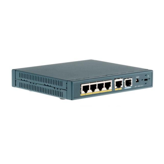
PIX 506/506E Product Overview This section describes the PIX 506/506E front and rear panels and the panel LEDs. Figure 3-1 shows the front view of the PIX 506/506E. Figure 3-1 PIX 506/506E Front Panel Cisco PIX Security Appliance Hardware Installation Guide 78-15170-03... - Page 36 The unit has power. Green Flashing Active indicator—On when the software image has been loaded on the security appliance. NETWORK Green Flashing On when at least one network interface is passing traffic. Cisco PIX Security Appliance Hardware Installation Guide 78-15170-03...
-
Page 37: Installing The Pix 506/506E
Use the RJ-45 Console port to connect a computer to enter configuration commands. Locate the Note serial cable from the accessory kit. The serial cable assembly consists of a null modem cable with RJ-45 connectors, and one DB-9 connector and one DB-25 connector. Cisco PIX Security Appliance Hardware Installation Guide 78-15170-03... -
Page 38: Connecting A Power Supply Module To The Pix 506/506E
The PIX 506/506E uses an external AC to DC power supply. Power is supplied to the PIX 506/506E by connecting the power supply to the back of the security appliance and connecting a separate AC power cord to the power supply. Cisco PIX Security Appliance Hardware Installation Guide 78-15170-03... - Page 39 Step 2 Figure 3-7 for the PIX 506E. When you are ready to start the PIX 506/506E, power on the unit from the switch at the rear of the unit. Step 3 Cisco PIX Security Appliance Hardware Installation Guide 78-15170-03...
-
Page 40: Removing And Replacing The Pix 506/506E Chassis Cover
Removing the Chassis Cover To remove the chassis cover, perform the following steps: Removing the chassis cover does not affect your Cisco warranty. Upgrading the PIX security appliance Note does not require any special tools and does not create any radio frequency leaks. -
Page 41: Replacing The Chassis Cover
When the battery loses its charge, the PIX security appliance cannot function. The battery is a field-replaceable unit (FRU). You can use a standard 3V lithium battery to replace the used battery. Cisco PIX Security Appliance Hardware Installation Guide 78-15170-03... - Page 42 Step 5 cover back into the side and front panel slots on the chassis. Replace the chassis cover as described in the “Replacing the Chassis Cover” section on page 3-7. Step 6 Cisco PIX Security Appliance Hardware Installation Guide 78-15170-03...
-
Page 43: Pix 515/515E Product Overview
Note PIX 515/515E Product Overview This section describes the front and rear panels and the panel LEDs. Figure 4-1 shows the front view of the chassis. Figure 4-1 PIX 515/515E Front Panel Cisco PIX Security Appliance Hardware Installation Guide 78-15170-03... - Page 44 Off when the unit is in standby mode. If failover is not enabled, this light is off. NETWORK Green Flashing On when at least one network interface is passing traffic. Cisco PIX Security Appliance Hardware Installation Guide 78-15170-03...
-
Page 45: Installing The Pix 515/515E
Surface Mounting the PIX 515/515E, page 4-4 • Removing and Replacing the PIX 515/515E Chassis Cover, page 4-13 • Vertical Mounting the PIX 515/515E, page 4-5 • Installing a Circuit Board in the PIX 515/515E, page 4-19 • Cisco PIX Security Appliance Hardware Installation Guide 78-15170-03... -
Page 46: Surface Mounting The Pix 515/515E
Figure 4-5 Attaching the Rubber Feet to the PIX 515/515E Unused Cisco PIX Security Appliance Hardware Installation Guide 78-15170-03... -
Page 47: Rack Mounting The Pix 515/515E
Vertical Mounting the PIX 515/515E To mount the chassis vertically, attach the brackets to the side of the unit and mount the unit vertically as shown in Figure 4-6. Figure 4-6 Installing the PIX 515/515E Vertically Cisco PIX Security Appliance Hardware Installation Guide 78-15170-03... -
Page 48: Installing The Pix 515/515E
Ethernet circuit boards, refer to Figure 4-9. If you need to install an optional circuit board, refer to the “Removing and Replacing the PIX 515/515E Chassis Cover” section on page 4-13 for more information. Cisco PIX Security Appliance Hardware Installation Guide 78-15170-03... - Page 49 Do not power on the failover units until the active unit has been configured. Note Power on the unit from the switch at the rear to start the PIX 515/515E. Step 4 Cisco PIX Security Appliance Hardware Installation Guide 78-15170-03...
-
Page 50: Pix 515/515E Feature Licenses
For information on upgrading feature licenses or downloading the latest software versions, refer to the configuration guide online http://www.cisco.com/en/US/products/sw/secursw/ps2120/prod_configuration_guides_list.html This section includes the following topics: • VPN Accelerator Card, page 4-9 VPN Accelerator Card+, page 4-9 • Cisco PIX Security Appliance Hardware Installation Guide 78-15170-03... -
Page 51: Vpn Accelerator Card
Installing Failover VPN Accelerator Card The VPN Accelerator Card (VAC) for the Cisco PIX security appliance series is a card that provides high-performance, tunneling and encryption services suitable for site-to-site and remote access applications. The VAC is integrated with PIX 515 unrestricted (UR) and failover (FO) bundles. You can also purchase the VAC as a spare for use with PIX 515s that have a restricted (R) license. - Page 52 Category 5 crossover cable directly connecting the primary unit to the secondary unit • • 100BaseTX half-duplex hub using Straight-through Category 5 cables 100BaseTX full duplex on a dedicated switch or dedicated VLAN of a switch • Cisco PIX Security Appliance Hardware Installation Guide 4-10 78-15170-03...
- Page 53 Use the power switch at the back of the units to power on the primary unit and then power on the standby Step 7 unit. Within a few seconds, the active unit automatically downloads its configuration to the standby unit. If the primary unit fails, the secondary unit automatically becomes active. Cisco PIX Security Appliance Hardware Installation Guide 4-11 78-15170-03...
-
Page 54: Installing Lan-Based Failover
100 Mbps Link FAILOVER 10/100 ETHERNET 1 10/100 ETHERNET 0 CONSOLE 100 Mbps Link 100 Mbps Link FAILOVER 10/100 ETHERNET 1 10/100 ETHERNET 0 CONSOLE Dedicated Ethernet Dedicated Ethernet interface interface Hub/switch Cisco PIX Security Appliance Hardware Installation Guide 4-12 78-15170-03... -
Page 55: Removing And Replacing The Pix 515/515E Chassis Cover
Removing the Chassis Cover To remove the chassis cover, perform the following steps: Removing the chassis cover does not affect your Cisco warranty. Upgrading the PIX security appliance Note does not require any special tools and does not create any radio frequency leaks. - Page 56 Pull the chassis cover up as shown in Figure 4-15. Put the chassis cover in a safe place. Step 5 Figure 4-15 Pull the Chassis Cover up to Remove PIX Firewall SERIES POWER NETWORK Cisco PIX Security Appliance Hardware Installation Guide 4-14 78-15170-03...
-
Page 57: Replacing The Chassis Cover
The PIX security appliance has a lithium battery on its main circuit board. This battery has an operating life of about ten years. When the battery loses its charge, the PIX security appliance cannot function. The lithium battery is not a field-replacable unit (FRU) for the PIX 515/515E. Contact Cisco TAC to replace the battery. -
Page 58: Installing A Memory Upgrade
PIX 515/515E Minimum Memory Requirements Software Software Version 6.3 Software Version 7.0 and License and Previous Releases Later Releases Restricted 32 MB 64 MB Unrestricted 64 MB 128 MB Failover 64 MB 128 MB Cisco PIX Security Appliance Hardware Installation Guide 4-16 78-15170-03... - Page 59 Determine the location of the memory sockets (see Figure 4-16). Step 5 Figure 4-16 PIX 515/515E System Memory Location Memory sockets Cisco PIX Security Appliance Hardware Installation Guide 4-17 78-15170-03...
- Page 60 Use the markings on the motherboard to determine the socket numbers. Always install the first memory module into the lowest socket number. Then populate the second memory socket. See Figure 4-18 Figure 4-19. Cisco PIX Security Appliance Hardware Installation Guide 4-18 78-15170-03...
-
Page 61: Installing A Circuit Board In The Pix 515/515E
Installing a Circuit Board in the PIX 515/515E This section includes the following topics: Fast Ethernet Circuit Board, page 4-20 • VPN Accelerator Circuit Board, page 4-22 • Cisco PIX Security Appliance Hardware Installation Guide 4-19 78-15170-03... -
Page 62: Fast Ethernet Circuit Board
100 Mbps FAILOVER Link 10/100 ETHERN ET 0/0 10/100 ETHERN ET 0/0 CONSOL E Remove the screws from the rear assembly on the left and put the assembly aside. Step 2 Cisco PIX Security Appliance Hardware Installation Guide 4-20 78-15170-03... - Page 63 Attach the screw to hold the circuit board connecting flange to the cover plate, and install the screws to Step 5 attach the cover plate to the PIX 515/515E. Reattach the chassis cover. Step 6 Cisco PIX Security Appliance Hardware Installation Guide 4-21 78-15170-03...
-
Page 64: Vpn Accelerator Circuit Board
The new VPN Accelerator cannot be used with the former PIX security appliance IPSec accelerator in Note the same chassis. The PIX security appliance IPSec accelerator was also known as the Private Link card. Cisco PIX Security Appliance Hardware Installation Guide 4-22 78-15170-03... -
Page 65: Installing The Pix 515/515E Dc Model
2-hole copper standard barrel grounding lug must be NRTL listed or recognized Strip the ends of the wires for insertion into the power connect lugs on the PIX 515/515E. Step 5 Cisco PIX Security Appliance Hardware Installation Guide 4-23 78-15170-03... - Page 66 Power on the unit from the switch at the rear of the unit. Step 9 If you need to power cycle the DC PIX 515/515E, wait at least five seconds between powering off the Note unit and powering it back on. Cisco PIX Security Appliance Hardware Installation Guide 4-24 78-15170-03...
-
Page 67: Chapter 5 Pix
This section describes the PIX 520 front and rear panels and the panel LEDs. Figure 5-1 shows the front view of the PIX 520. Figure 5-1 PIX 520 Front Panel PIX Fir ew all RESET SERI ES Cisco PIX Security Appliance Hardware Installation Guide 78-15170-03... - Page 68 With the four-port Ethernet circuit board, having a circuit board in slot 3 makes the number of interfaces greater than six; while the circuit board in slot 3 cannot be accessed, its presence does not cause problems with the PIX security appliance. Cisco PIX Security Appliance Hardware Installation Guide 78-15170-03...
- Page 69 Figure 5-5 Single-Port Ethernet Circuit Board Installed in Slot 0 and 1 and Four-Port Ethernet Circuit Board Installed in Slot 2 Interface 2 Interface 3 Interface 4 Interface 5 Interface 0 Interface 1 Cisco PIX Security Appliance Hardware Installation Guide 78-15170-03...
-
Page 70: Installing The Pix 520
Right side Connect network cables to each of the PIX security appliance network interfaces. On the PIX 520, Step 2 connect the cables at the front of the unit. Cisco PIX Security Appliance Hardware Installation Guide 78-15170-03... - Page 71 If you are installing an AC voltage PIX security appliance, connect the power cord to the power Step 5 connector on the rear panel of the PIX security appliance, and to a power outlet. Cisco PIX Security Appliance Hardware Installation Guide 78-15170-03...
-
Page 72: Pix 520 Feature Licenses
If you need to install additional memory, refer to the “Installing a Memory Upgrade” section on • page 5-12. Cisco PIX Security Appliance Hardware Installation Guide 78-15170-03... -
Page 73: Installing Failover
All enabled interfaces must be connected between the active and standby units. Only configure the • active unit. On the PIX 520, you can access the console and determine which unit is active with the show failover command in the command reference online at: http://cisco.com/en/US/products/sw/secursw/ps2120/prod_command_reference_list.html. Cisco PIX Security Appliance Hardware Installation Guide 78-15170-03... -
Page 74: Installing Lan-Based Failover
5-10. A dedicated LAN interface and a dedicated switch (or VLAN) is required to implement Note LAN-based failover. You cannot use a crossover Ethernet cable to connect the two PIX security appliances. Cisco PIX Security Appliance Hardware Installation Guide 78-15170-03... - Page 75 Power the primary unit on first, then power on the secondary unit. Within a few seconds, the active unit automatically downloads its configuration to the standby unit. If the primary unit fails, the secondary unit automatically becomes active. Cisco PIX Security Appliance Hardware Installation Guide 78-15170-03...
-
Page 76: Removing And Replacing The Pix 520 Chassis Cover
Removing the Chassis Cover To remove the chassis cover, perform the following steps: Removing the PIX security appliance case does not affect your Cisco warranty. Upgrading the Note PIX security appliance does not require any special tools and does not create any radio frequency leaks. -
Page 77: Replacing The Chassis Cover
Replace the chassis cover, as shown in Figure 5-13. Step 1 Secure the three screws. Step 2 Reinstall all interface cables. Step 3 Figure 5-13 Replacing the Chassis Cover PIX Fir ew all RESET SERI ES Cisco PIX Security Appliance Hardware Installation Guide 5-11 78-15170-03... -
Page 78: Replacing A Lithium Battery
The PIX security appliance has a lithium battery on its main circuit board. This battery has an operating life of about ten years. When the battery loses its charge, the PIX security appliance cannot function. The lithium battery is not a field-replacable unit (FRU). Contact Cisco TAC to replace the battery. Note Do not attempt to replace this battery yourself. -
Page 79: Memory Installation Steps
When installing the memory strip in the PIX 520, install the new strip in Bank 0 as shown in • Figure 5-15 Figure 5-16, by opening the two plastic wing connectors, inserting the strip, and closing the wing connectors. Cisco PIX Security Appliance Hardware Installation Guide 5-13 78-15170-03... - Page 80 After the PIX security appliance is installed, you can view the amount of RAM memory in the system startup messages or with the show version command in the command reference online at: http://cisco.com/en/US/products/sw/secursw/ps2120/prod_command_reference_list.html. Cisco PIX Security Appliance Hardware Installation Guide 5-14 78-15170-03...
-
Page 81: Installing A Circuit Board In The Pix 520
PI X Fir ew all RESET POWE R SERI ES Insert the new circuit board, as shown in Figure 5-18, and secure it using the screw provided with the Step 2 circuit board. Cisco PIX Security Appliance Hardware Installation Guide 5-15 78-15170-03... - Page 82 When adding a network interface or encryption circuit board, install the new circuit board in the Note first empty slot to the right of the existing network interface circuit board. Figure 5-19 PIX Security Appliance Network Circuit Boards Interface 3 Interface 2 Interface 1 Interface 0 Cisco PIX Security Appliance Hardware Installation Guide 5-16 78-15170-03...
- Page 83 If you are installing a 4-port circuit board, note that the circuit board will overlap the slot connector on Step 4 the motherboard. This does not affect the use or operation of the circuit board. See Figure 5-20. Figure 5-20 4-Port Circuit Board Overlap Overlap Cisco PIX Security Appliance Hardware Installation Guide 5-17 78-15170-03...
-
Page 84: 16 Mb Flash Circuit Board
5.0 | 5.1 | 5.2 options if your PIX security appliance has 16 MB Flash memory, private data stored in the Flash memory, and you used the ca save all command to save these items in Flash memory. Cisco PIX Security Appliance Hardware Installation Guide 5-18 78-15170-03... -
Page 85: Vpn Accelerator Circuit Board
The new VPN Accelerator cannot be used with the former PIX security appliance IPSec accelerator in the same chassis. The PIX security appliance IPSec accelerator was also known as the Private Link card. Cisco PIX Security Appliance Hardware Installation Guide 5-19... -
Page 86: Gigabit Ethernet Circuit Board
PIX security appliance supports 1000 Mbps (Gigabit) Ethernet. The Gigabit Ethernet circuit board uses only has one hardware speed and the following duplex options: 1000SXfull—Forces full-duplex operation • 1000BaseSX—Forces half-duplex operation • • 1000auto—Auto negotiates full or half duplex Cisco PIX Security Appliance Hardware Installation Guide 5-20 78-15170-03... -
Page 87: Installing The Pix 520 Dc Model
48 VDC facility power source. An easily accessible disconnect device should be incorporated into the facility wiring. Step 3 Be sure the PIX 520 power is off by checking the power switch at the rear of the unit. Cisco PIX Security Appliance Hardware Installation Guide 5-21 78-15170-03... - Page 88 Insert the ground wire into the connector for the earth ground and tighten the screw on the connector (see Step 7 Figure 5-25). Using the same method as for the ground wire, connect the negative wire and then the positive wire. Figure 5-25 Attaching DC Power Cables – Cisco PIX Security Appliance Hardware Installation Guide 5-22 78-15170-03...
- Page 89 Power on the unit from the switch at the rear of the unit. Step 11 If you need to power cycle the DC PIX security appliance, wait at least five seconds between powering Note off the unit and powering it back on. Cisco PIX Security Appliance Hardware Installation Guide 5-23 78-15170-03...
- Page 90 Chapter 5 PIX 520 Installing the PIX 520 DC Model Cisco PIX Security Appliance Hardware Installation Guide 5-24 78-15170-03...
-
Page 91: Chapter 6 Pix
PIX 525. Figure 6-1 PIX 525 Front Panel CISC O SECU RITY PIX SERIES F I R E W A L L POWE R ACTIV E Cisco PIX Security Appliance Hardware Installation Guide 78-15170-03... - Page 92 Off when the unit is in standby mode. There are three LEDs for the each RJ-45 interface port and three types of fixed interface connectors on the back of the PIX 525. Cisco PIX Security Appliance Hardware Installation Guide 78-15170-03...
-
Page 93: Installing The Pix 525
Attach the brackets to the holes near the front of the unit on each side of the PIX 525 using the supplied screws. Attach the unit to the equipment rack. Cisco PIX Security Appliance Hardware Installation Guide 78-15170-03... - Page 94 “Installing a Memory Upgrade” section on page 6-12 for more information. Note It is not necessary to remove the chassis cover of the PIX 525 to access the circuit boards or memory. Cisco PIX Security Appliance Hardware Installation Guide 78-15170-03...
-
Page 95: Pix 525 Feature Licenses
For information on upgrading feature licenses or downloading the latest software versions, refer to the configuration guide online http://www.cisco.com/en/US/products/sw/secursw/ps2120/prod_configuration_guides_list.html This section includes the following topics: VPN Accelerator Card, page 6-6 • VPN Accelerator Card+, page 6-6 • Cisco PIX Security Appliance Hardware Installation Guide 78-15170-03... -
Page 96: Vpn Accelerator Card
Installing Failover VPN Accelerator Card The VPN Accelerator Card (VAC) for the Cisco PIX security appliance series is a card that provides high-performance, tunneling and encryption services suitable for site-to-site and remote access applications. The VAC is integrated with PIX 525 unrestricted (UR) and failover (FO) bundles. You can also purchase the VAC as a spare for use with PIX 525 units that have a restricted (R) license. - Page 97 Power on the primary unit first, then power on the secondary unit. Within a few seconds, the active unit Step 7 automatically downloads its configuration to the standby unit. If the primary unit fails, the secondary unit automatically becomes active. Cisco PIX Security Appliance Hardware Installation Guide 78-15170-03...
-
Page 98: Installing Lan-Based Failover
100Mbps ACT LINK PIX-525 10/100 ETHERNET 1 10/100 ETHERNET 0 CONSOLE 100Mbps ACT LINK 100Mbps ACT LINK PIX-525 10/100 ETHERNET 1 10/100 ETHERNET 0 CONSOLE Dedicated Ethernet Dedicated Ethernet interface interface Hub/switch Cisco PIX Security Appliance Hardware Installation Guide 78-15170-03... -
Page 99: Removing And Replacing The Pix 525 Chassis Cover
Replacing the Chassis Cover, page 6-11 • Removing the Chassis Cover Removing the PIX security appliance chassis cover does not affect your Cisco warranty. Upgrading the Note PIX security appliance does not require any special tools and does not create any radio frequency leak. - Page 100 Figure 6-9 Removing the Chassis Cover Chassis cover T IV C I S S E C I T Y P I X 5 2 5 R IE Chassis bottom Front panel Cisco PIX Security Appliance Hardware Installation Guide 6-10 78-15170-03...
-
Page 101: Replacing The Chassis Cover
5 2 5 R IE Front panel Chassis bottom Step 6 Connect the power to the site power and power on the PIX 525. The internal power supply fan should go Cisco PIX Security Appliance Hardware Installation Guide 6-11 78-15170-03... -
Page 102: Replacing A Lithium Battery
The PIX security appliance has a lithium battery on its main circuit board. This battery has an operating life of about ten years. When the battery loses its charge, the PIX security appliance cannot function. The lithium battery is not a field-replacable unit (FRU). Contact Cisco TAC to replace the battery. Note Do not attempt to replace this battery yourself. -
Page 103: Memory Installation Steps
When installing the memory strip in a PIX 525, install the new strip in Bank 0 as shown in • Figure 6-12 Figure 6-13, by opening the two plastic wing connectors, inserting the strip, and closing the wing connectors. Cisco PIX Security Appliance Hardware Installation Guide 6-13 78-15170-03... - Page 104 PIX security appliance and attach all cables and cords as discussed in previous sections. After the PIX security appliance is installed, you can view the amount of RAM memory in the system startup messages or with the show version command. Cisco PIX Security Appliance Hardware Installation Guide 6-14 78-15170-03...
-
Page 105: Installing A Circuit Board In The Pix 525
Attach the other end to bare metal on the PIX 525 chassis. Step 2 Remove the screws from the rear panel of the component tray and slide the tray out (see Figure 6-14). Cisco PIX Security Appliance Hardware Installation Guide 6-15 78-15170-03... - Page 106 PCI slots on the component tray. Step 6 Figure 6-16 Expansion Boards in PCI Slots on the PIX 525 Component Tray Step 7 Reinstall the component tray into the PIX 525 chassis. Cisco PIX Security Appliance Hardware Installation Guide 6-16 78-15170-03...
-
Page 107: Fast Ethernet Circuit Board
If you are installing a 4-port circuit board, note that the circuit board overlaps the slot connector Note on the motherboard. This does not affect the use or operation of the circuit board. See Figure 6-17. Cisco PIX Security Appliance Hardware Installation Guide 6-17 78-15170-03... -
Page 108: Vpn Accelerator Circuit Board
• 1000BaseSX—Forces half-duplex operation • 1000auto—Auto negotiates full or half duplex • We highly recommend that you use a GE failover link when connecting the PIX 525 with GE interfaces. Note Cisco PIX Security Appliance Hardware Installation Guide 6-18 78-15170-03... -
Page 109: Installing A Dc Power Supply
Reinstall the three screws that secure the power supply on the back panel of the chassis. Step 2 Cisco PIX Security Appliance Hardware Installation Guide 6-19 78-15170-03... - Page 110 The connectors to these two fans will fit into the space between the second and third fans. Step 5 Reconnect the power connector. Cisco PIX Security Appliance Hardware Installation Guide 6-20 78-15170-03...
- Page 111 Step 6 the cables to the two installed fans so that they will fit over the first and second fans. Press the fan into place between the four sheet metal tabs. Cisco PIX Security Appliance Hardware Installation Guide 6-21 78-15170-03...
- Page 112 Installing a DC Power Supply Reconnect the two-pin fan cables to the remaining fan, as shown in Figure 6-22. Step 7 Figure 6-22 Reconnecting the Fan Cables Fan connector Front panel Cisco PIX Security Appliance Hardware Installation Guide 6-22 78-15170-03...
- Page 113 Starting with the fan farthest away from the power supply, bend the cable clamps over wires and into Step 9 the gap between chassis and fan housing. Figure 6-23 Correct Fan Cable Routing Sheet metal tabs Base tabs Front panel Cisco PIX Security Appliance Hardware Installation Guide 6-23 78-15170-03...
-
Page 114: Rerouting The Fan Wiring
Step 10 Step 11. The remaining cable goes to the power connector on the backplane. These cables are color-coded. Cisco PIX Security Appliance Hardware Installation Guide 6-24 78-15170-03... - Page 115 Lift the fan out of the chassis as shown in Figure 6-26. Step 2 Figure 6-26 Removing the Fan Chassis bottom Depress the tab as shown in Figure 6-27. Step 3 Cisco PIX Security Appliance Hardware Installation Guide 6-25 78-15170-03...
- Page 116 Make sure that the label on the fan faces the chassis wall to ensure proper airflow direction. Note Install cable clamps onto the fans by aligning cable clamp holes over fan mounting holes and pressing Step 8 rivets through both. (See Figure 6-28.) Cisco PIX Security Appliance Hardware Installation Guide 6-26 78-15170-03...
- Page 117 PIX 525 to connect a copper standard barrel grounding lug to the studs. The PIX 525 requires a lug where the distance between the center of each hole is 0.56 inches. A lug is not supplied with the PIX 525. Cisco PIX Security Appliance Hardware Installation Guide 6-27...
- Page 118 Using the same method as for the ground wire, connect the negative wire and then the positive wire. Figure 6-30 Attaching DC Power Cables – Cisco PIX Security Appliance Hardware Installation Guide 6-28 78-15170-03...
- Page 119 Power on the unit from the switch at the rear of the unit. If you need to power cycle the DC PIX security appliance, wait at least 5 seconds between powering off the unit and powering it back on. Cisco PIX Security Appliance Hardware Installation Guide 6-29 78-15170-03...
- Page 120 Chapter 6 PIX 525 Installing a DC Power Supply Cisco PIX Security Appliance Hardware Installation Guide 6-30 78-15170-03...
-
Page 121: Chapter 7 Pix
If you need to remove the PIX 535 chassis cover for any reason, use the related information in the “Removing and Replacing the PIX 515/515E Chassis Cover” section on page 4-13 as a guideline. Cisco PIX Security Appliance Hardware Installation Guide 78-15170-03... - Page 122 PIX 535 front panel LEDs. Figure 7-3 PIX 535 Front Panel LEDs PO W ER AC TIV E CISC O SECU RITY PIX SERIES F I R E W A L L POWE R ACTIV E Cisco PIX Security Appliance Hardware Installation Guide 78-15170-03...
- Page 123 Shows that data is passing through that interface. Shows that the connection uses full-duplex data exchange where data can be transmitted and received simultaneously. If this light is off, half duplex is in effect. Cisco PIX Security Appliance Hardware Installation Guide 78-15170-03...
-
Page 124: Pix 535 Network Interface Description
The VPN Accelerator Card+ (PIX-VACPLUS) should always be installed in a 64-bit/66 MHz card • slot. VPN performance will be degraded by roughly a factor of 4 if this recommendation is not followed. Cisco PIX Security Appliance Hardware Installation Guide 78-15170-03... -
Page 125: Installing The Pix 535
Attach the mounting brackets to the unit using the supplied screws. Step 1 Attach the brackets to the holes near the front on both sides of the unit. Step 2 Attach the unit to the equipment rack. Step 3 Cisco PIX Security Appliance Hardware Installation Guide 78-15170-03... -
Page 126: Pix 535 Network Interface Installation
“Installing a Circuit Board in the • PIX 535” section on page 7-14. If you need to install additional memory, refer to the “Installing a Memory Upgrade” section on • page 7-11. Cisco PIX Security Appliance Hardware Installation Guide 78-15170-03... -
Page 127: Vpn Accelerator Card
VPN Accelerator Card+, page 7-7 VPN Accelerator Card The VPN Accelerator Card (VAC) for the Cisco PIX security appliance series is a card that provides high-performance, tunneling and encryption services suitable for site-to-site and remote access applications. The VAC is integrated with PIX 535 unrestricted (UR) and failover (FO) bundles. You can also purchase the VAC as a spare for use with PIX 535 units that have a restricted (R) license. -
Page 128: Installing Failover
1000BaseTX full duplex on a dedicated switch or dedicated VLAN of a switch • For Stateful Failover on the PIX 535, you must use a Gigabit Ethernet (GE) failover link with Note GE interfaces. Cisco PIX Security Appliance Hardware Installation Guide 78-15170-03... -
Page 129: Installing Lan-Based Failover
Step 4 A dedicated LAN interface and a dedicated switch (or VLAN) is required to implement Note LAN-based failover. You cannot use a crossover Ethernet cable to connect the two PIX security appliances. Cisco PIX Security Appliance Hardware Installation Guide 78-15170-03... -
Page 130: Replacing A Lithium Battery
When the battery loses its charge, the PIX security appliance cannot function. The lithium battery is not a field-replaceable unit (FRU). Contact Cisco TAC to replace the battery. Do not attempt to replace this battery yourself. -
Page 131: Installing A Memory Upgrade
PIX security appliance chassis. Attach the other end to your wrist, making sure that it contacts your bare skin. At the rear panel of the chassis, loosen the attachment screws that hold the component tray in place and Step 6 slide the tray out. Cisco PIX Security Appliance Hardware Installation Guide 7-11 78-15170-03... - Page 132 (J40 and J43 in Bank 0 or J41 and J44 in Bank 1). Figure 7-7 System Memory Location on the PIX 535 Component Tray Memory sockets Cisco PIX Security Appliance Hardware Installation Guide 7-12 78-15170-03...
- Page 133 Reinstall the component tray and the screws that hold the assembly in place. Step 9 Step 10 Remove the grounding wrist-strap. Rack-mount the chassis or place it on a flat, stable surface. Step 11 Cisco PIX Security Appliance Hardware Installation Guide 7-13 78-15170-03...
-
Page 134: Installing A Circuit Board In The Pix 535
Table 7-4 applies only to PIX security appliance Version 6.1(1) and later. Earlier versions of Note PIX security appliance support fewer interface options. Cisco PIX Security Appliance Hardware Installation Guide 7-14 78-15170-03... - Page 135 2 4-port FE + 2 FE + 1 VPN Accelerator 1 4-port FE card + 6 FE 1 4-port FE card + 6 FE + 1 VPN Accelerator 1GE + 1FE + 2 x 4FE cards Cisco PIX Security Appliance Hardware Installation Guide 7-15 78-15170-03...
-
Page 136: Circuit Board Slot Description
64-bit/66 MHz bus (Bus 0 or Bus 1). The overall speed of the bus will be reduced by the lower speed circuit board. • The VPN Accelerator circuit board should only be installed in the 32-bit/33 MHz Bus. Cisco PIX Security Appliance Hardware Installation Guide 7-16 78-15170-03... -
Page 137: Installing A Circuit Board
Use the screw that was removed in Step 3 to attach the circuit board front plate to the component tray Step 5 rear panel. Step 6 Reinstall the component tray and tighten the attachment screws. Cisco PIX Security Appliance Hardware Installation Guide 7-17 78-15170-03... -
Page 138: 16 Mb Flash Circuit Board
Along with upgrading your Flash memory to 16 MB, the PIX security appliance 16 MB Flash circuit board includes pre-installed PIX security appliance software and a UR (unrestricted) 56-bit DES encryption license. The 16 MB Flash circuit board installs into the PIX security appliance ISA slot. Cisco PIX Security Appliance Hardware Installation Guide 7-18 78-15170-03... - Page 139 16 MB Flash circuit board. Create a backup of your present configuration (to use later to reconfigure your system). Step 3 Obtain a new Activation key (if using 3DES). Step 4 Cisco PIX Security Appliance Hardware Installation Guide 7-19 78-15170-03...
-
Page 140: Vpn Accelerator Circuit Board
PIX security appliance supports 1000 Mbps (Gigabit) Ethernet. The Gigabit Ethernet circuit board has only one hardware speed and supports the following duplex options: 1000SXfull—Forces full-duplex operation • • 1000BaseSX—Forces half-duplex operation • 1000auto—Auto negotiates full or half duplex Cisco PIX Security Appliance Hardware Installation Guide 7-20 78-15170-03... -
Page 141: Installing The Pix 535 Dc Model
Remove the blank cover plate, if a blank cover plate is installed on the PIX 535. Read the Regulatory Compliance and Safety Information document for your respective software version. Step 2 Cisco PIX Security Appliance Hardware Installation Guide 7-21 78-15170-03... - Page 142 Using the same method as for the ground wire, connect the negative wire and then the positive wire. Figure 7-17 Attaching DC Power Cables – Cisco PIX Security Appliance Hardware Installation Guide 7-22 78-15170-03...
- Page 143 If you need to power cycle the DC PIX 535, wait at least 5 seconds between powering off the unit and powering it back on. Your unit is now ready to configure. Refer to the configuration guide online http://www.cisco.com/en/US/products/sw/secursw/ps2120/prod_configuration_guides_list.html. Cisco PIX Security Appliance Hardware Installation Guide 7-23 78-15170-03...
- Page 144 Chapter 7 PIX 535 Installing the PIX 535 DC Model Cisco PIX Security Appliance Hardware Installation Guide 7-24 78-15170-03...
-
Page 145: Appendix
Figure A-1 shows the 10BaseT and the 100BaseTX connector (RJ-45). Figure A-1 RJ-45 10BaseT and 100BaseTX Connector Table A-1 shows the connector pinout. Table A-1 10BaseT and 100BaseTX Connector (RJ-45) Pinouts Description Cisco PIX Security Appliance Hardware Installation Guide 78-15170-03... - Page 146 Cisco products use the following three types of RJ-45 cables: • Straight-through Crossover • Rolled • Cisco does not provide these cables; they are widely available from other sources. Note Figure A-2 shows the RJ 45 cable. Figure A-2 RJ-45 Cable 8 7 6 5 4 3 2 1...
- Page 147 (see Table A-4). Table A-2 RJ-45 Straight-Through (Ethernet) Cable Pinouts Signal Pin Table A-3 RJ-45 Crossover (Ethernet) Cable Pinouts Signal Pin Table A-4 RJ-45 Rolled (Console) Cable Pinouts Signal Pin Cisco PIX Security Appliance Hardware Installation Guide 78-15170-03...
- Page 148 Stateful Failover dedicated interface. Figure A-4 Stateful Failover Dedicated Interface Crossover Cable Pinouts Primary unit Secondary unit 3 TxD+ 3 TxD+ 6 TxD– 6 TxD– 1 RxD+ 1 RxD+ 2 RxD– 2 RxD– Cisco PIX Security Appliance Hardware Installation Guide 78-15170-03...
- Page 149 11 —— Plug Driver 4 —————————————————— 6 ———————— Primary Select 12 —— —— 12 Secondary Select Ground 5 ————————————————————— 5 Loopback —— 6 ————————————————————— 4 Inside —— 11 Chassis —— 14 ———————————————————— 9 Cisco PIX Security Appliance Hardware Installation Guide 78-15170-03...
- Page 150 Appendix A Cable Pinouts Failover Cable Pinouts Cisco PIX Security Appliance Hardware Installation Guide 78-15170-03...
-
Page 151: I N D E X
AC power supply 7-11 ACT LEDs cables PIX 506/506E clamps PIX 515/515E PIX 525 6-23, 6-27 PIX 525 failover PIX 535 lock air separator PIX 501 replacing 6-24 serial PIX 506/506E PIX 525 Cisco PIX Security Appliance Hardware Installation Guide IN-1 78-15170-03... - Page 152 PIX 515/515E PIX 525 ETHERNET 1 PIX 506/506E DB-15 failover connector PIX 515/515E DB-9 connector and DB-25 connector PIX 525 PIX 506/506E ethernet circuit boards PIX 515/515E PIX 515/515E PIX 520 Cisco PIX Security Appliance Hardware Installation Guide IN-2 78-15170-03...
- Page 153 PIX 520 5-20 IPSec accelerators PIX 525 6-18 VPN accelerator and (note) 5-19 PIX 535 7-20 LEDs PIX 520 5-21 PIX 525 6-19 lights PIX 535 7-21 see LEDs grounding lug 7-22 Cisco PIX Security Appliance Hardware Installation Guide IN-3 78-15170-03...
- Page 154 PIX 506/506E installing PIX 515/515E product overview PIX 520 replacing lithium battery PIX 525 PIX 515/515E PIX 535 connectors power supplies feature licenses connecting inserting boards 4-21 PIX 501 installing PIX 506/506E Cisco PIX Security Appliance Hardware Installation Guide IN-4 78-15170-03...
- Page 155 PIX 520 5-22 SIMM strip 7-13 PIX 535 7-22 site environment wrist straps Stateful Failover PIX 515/515E 4-18 connecting dedicate interfaces PIX 520 5-13 PIX 515/515E 4-10 PIX 525 6-13 PIX 520 Cisco PIX Security Appliance Hardware Installation Guide IN-5 78-15170-03...
- Page 156 Index Cisco PIX Security Appliance Hardware Installation Guide IN-6 78-15170-03...