Table of Contents
Advertisement
Quick Links
Advertisement
Table of Contents

Related Manuals for LAUNCH TECH X-431

Summary of Contents for LAUNCH TECH X-431
- Page 1 User Manual Version: V1.00.000 Revised date: 3-26-2018 Statement: All information, specifications and illustrations in this manual are based on the latest information available at the time of release. LAUNCH reserves the rights to make changes at any time without notice.
- Page 2 X-431 Throttle User Manual Copyright Information Copyright © 2018 by LAUNCH TECH. CO., LTD. All rights reserved. No part of this publication may be reproduced, stored in a retrieval system, or transmitted in any form or by any means, electronic, mechanical, photocopying, recording or otherwise, without the prior written permission of LAUNCH.
- Page 3 Do not insert foreign objects into or place heavy objects on your device. Sensitive components inside might cause damage. Do not use X-431 Throttle in exceptionally cold or hot, dusty, damp or dry environments. In places using X-431 Throttle may cause interference or generate a potential risk, please turn it off.
- Page 4 X-431 Throttle User Manual Precautions on Using X-431 Throttle Before using this test equipment, please read the following safety information carefully. Always perform automotive testing in a safe environment. If the diagnostic connector remains unused for a long period of time, it is suggested to unplug the connector from vehicle’s DLC to conserve battery...
- Page 5 X-431 Throttle User Manual Use extreme caution when performing any operations near the ECU or sensors. Ground yourself when you disassemble PROM, otherwise ECU and sensors can be damaged by static electricity. When reconnecting the ECU harness connector, be sure it is attached firmly,...
-
Page 6: Table Of Contents
1.3 T ............... 3 ECHNICAL PECIFICATIONS 1.3.1 X-431 Throttle handset ..............3 1.3.2 VCI connector ..................3 2 KNOWLEDGE OF X-431 THROTTLE ............. 5 2.1 X-431 T ................5 HROTTLE TABLET 2.1.1 Top view ..................... 5 2.1.2 Front view ..................6 2.1.3 Rear view ................... - Page 7 X-431 Throttle User Manual 3.9.2 Disconnect from a Wi-Fi network ............ 14 4 INITIAL USE ....................15 4.1 G ..................15 ETTING TARTED 4.2 R & D ........15 EGISTER OWNLOAD IAGNOSTIC OFTWARE 4.2.1 User registration ................15 4.2.2 Function modules ................18 4.2.3 Vehicle menu layout ................
- Page 8 X-431 Throttle User Manual 5.7 D ................55 IAGNOSTIC EEDBACK 5.8 V ..............56 EPAIR NFORMATION 6 SOFTWARE UPDATE ................... 58 6.1 U & APP........... 58 PDATE IAGNOSTIC OFTWARE 6.2 R ............59 ENEW SOFTWARE SUBSCRIPTION 7 PROFILE ......................60 7.1 P...
- Page 9 X-431 Throttle User Manual 9.1 P ................. 67 RODUCT UMMARY 9.2 S & A ..............68 TRUCTURE CCESSORIES 9.2.1 Sensorbox structure ................ 68 9.2.2 Sensorbox accessories ..............69 9.3 S ................70 ENSOR IMULATION 9.3.1 Connections ..................70 9.3.2 Simulation test ................. 70 9.3.3 Precautions on checking vehicle sensor .........
- Page 10 X-431 Throttle User Manual 12.4 O ..................91 PERATIONS 12.4.1 Channel selection and attributes setting ........91 12.4.2 Auto ....................96 12.4.3 View Settings ................. 96 12.4.4 Measure ..................97 12.4.5 File management ................99 12.4.6 Expert reference ................100 13 AUTOMOTIVE IGNITION WAVEFORM ............
-
Page 11: Introduction
Through simple Bluetooth communication / USB cable between the VCI device and X-431 Throttle handset, it achieves full car model and full system vehicle trouble diagnosis, which include Reading DTCs, Clearing DTCs, Reading Data Stream, Actuation Test and Special Functions. -
Page 12: Features
Backup/Restore: This feature lets you back up the recorded files to external storage device/restore the recorded data from external storage device. Add-on Modules: Scopebox, Sensorbox, Batterybox and Videoscope (sold separately) are available for extending the functions of X-431 Throttle. -
Page 13: Technical Specifications
LAUNCH X-431 Throttle User Manual 2. Compatible with Wi-Fi projecting technology: To mirror your X-431 Throttle screen onto an external projector or monitor with HD I/O interface via wireless technology. 3. Web browser: Users can make online search and visit any website. - Page 14 LAUNCH X-431 Throttle User Manual Standby current About 25mA Working temperature -20 ℃ to 55 ℃ (-4 ~131 ℉ ) Storage temperature -30 ℃ to 70 ℃ (-22~158 ℉ )
-
Page 15: Knowledge Of X-431 Throttle
2 Knowledge of X-431 Throttle There are three main components to the X-431 Throttle system: X-431 Throttle tablet – the central processor and monitor for the system (See Chapter “2.1”) Docking Station – the platform for charging X-431 Throttle tablet and extending functions (For details, please refer to Chapter 2.2.) -
Page 16: Front View
LAUNCH X-431 Throttle User Manual capture the current screenshot. Reserved for add-on modules (such as Data Batterybox, Scopebox and Sensorbox), and Transmission Port other devices with similar port. 2.1.2 Front view Fig. 2-2 To adjust the volume. Microphone It illuminates red while the handset is charging. -
Page 17: Rear View
LAUNCH X-431 Throttle User Manual 2.1.3 Rear view Fig. 2-3 Rear Camera Camera Flash Audio Speaker Align it with the charging slot on the docking Charging Slot station to charge the handset. Flip out it to any angle and work comfortable at Adjustable your desk, or hang it on automotive part. -
Page 18: Docking Station
The VCI connector works as a vehicle communication interface device, which is used to connect to the vehicle’s DLC (Data Link Connector) socket directly or via OBD II extension cable to read the vehicle data and then send it to the X-431 Throttle handset via wireless communication technology. - Page 19 LAUNCH X-431 Throttle User Manual Fig. 2-5 VCI connector OBD-16 diagnostic To connect on vehicle’s OBD II DLC. connector It lights up while the connector is plugged into Power indicator the vehicle’s DLC. It indicates wireless (BT) communication mode if the VCI is energized and illuminates...
-
Page 20: Package List
X-431 Throttle User Manual 2.4 Package List For different product configurations, the accessories may vary. For detailed accessory items, please consult from the local agency or check the package list supplied with X-431 Throttle together. Item Descriptions X-431 Throttle Indicates the test result. -
Page 21: Preparations
While X-431 Throttle has low battery, a beep will sound. If it is very low, X-431 Throttle will be switched off automatically. -
Page 22: Power Off
3.5 Lock & Unlock Screen Many screen lock modes are available on X-431 Throttle. *Note: You are recommended to set screen lock as “None” since X-431 Throttle is a frequently used diagnostic tool. 3.5.1 Lock the screen When it is ON, press [POWER] once to lock the screen;... -
Page 23: Unlock The Screen
VCI Connection not. 3.7 Adjust Brightness Tips: Reducing the brightness of the screen is helpful to save the power of X-431 Throttle. 1. On the home screen, tap Settings -> Display -> Brightness level. 2. Drag the slider to adjust it. -
Page 24: Changing Language
Note: Once WLAN is set as ON, X-431 Throttle will consume more power. While WLAN keeps unused, please turn it off to conserve battery power. X-431 Throttle has a built-in Wi-Fi module that can be used to get online. Once you’re online, you can register your X-431 Throttle, update the diagnostic software &... -
Page 25: Initial Use
LAUNCH X-431 Throttle User Manual 4 Initial Use 4.1 Getting Started For new users, please follow the operation chart shown in Fig. 4-1 to start using X-431 Throttle. Fig. 4-1 Note*: If “VIN Scan” function is performed, this step shall not apply. - Page 26 LAUNCH X-431 Throttle User Manual Fig. 4-2 A. If you are a new user, tap “New Customer” in Fig. 4-2 to start your sign-up. Fig. 4-3 a) Create App Account: In Fig. 4-3, fill in the information in each field (Items with * must be filled).
- Page 27 LAUNCH X-431 Throttle User Manual which can be found in the password envelope. Product SN Product SN Activation code Fig. 4-5 Note: To exit and activate it later, tap “Skip”. In this case, you can activate it by tapping “Activate VCI” in “Settings”.
-
Page 28: Function Modules
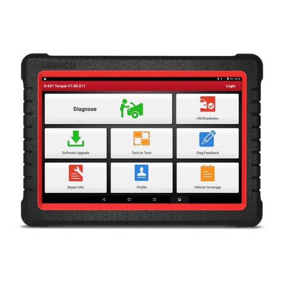
If you have registered to be a member, input your name and password, and then tap the “Login” button to enter the main menu screen directly. Note: The X-431 Throttle has an auto-save function. Once the username and password are correctly entered, the system will automatically store it. Next time you login the system, you will not be asked to input the account manually. - Page 29 Provides quick access to various authorized automotive Repair Info repair database. To manage personal information. Profile To view all the vehicle models that the X-431 Throttle Vehicle Coverage covers. Generally once a vehicle diagnosis is performed, X-431 Throttle will automatically record every details of diagnostic session.
-
Page 30: Vehicle Menu Layout
LAUNCH X-431 Throttle User Manual Toolbox mainly includes the following add-on modules: Fig. 4-9 Name Description To check unseen or unreachable parts or components. Videoscope To determine vehicle electrical equipment and circuit Oscilloscope/ trouble. Ignition To diagnose/simulate vehicle ECU sensor trouble. -
Page 31: Connections
AutoDetect: Through simple Bluetooth communication between the X-431 Throttle handset and VCI connector, you can easily get the VIN (Vehicle Identification Number) information of the currently identified vehicle. Once the VIN is successfully identified, the system will retrieve it from the remote server and then guide you to vehicle information page without the necessity of step-by-step manual menu selection. -
Page 32: Vehicle Connection
3. Choose one of the two ways to obtain power from: A. Power adaptor: Connect one end of the included power adaptor to DC IN port of X-431 Throttle tablet, and the other end to AC outlet. B. Internal battery pack For non-OBDII vehicle, proceed as follows: 1. -
Page 33: Communication Setup
OBD I adaptor. Fig. 4-13 4.4 Communication Setup There are two kinds of ways available for X-431 Throttle to pair with the VCI device. 4.4.1 Pairing up via wireless (BT) communication 1. -
Page 34: Usb Cable Connection
USB connection is successful. *Note: The USB connection provides the most stable and fastest communication. When all communication methods are applied at the same time, the X-431 Throttle system will use the USB communication as the default priority. -
Page 35: Diagnosis
LAUNCH X-431 Throttle User Manual 5 Diagnosis X-431 Throttle supports two kinds of diagnosis methods: Smart Diagnosis (AutoDetect) and Manual Diagnosis. 5.1 Intelligent Diagnosis (AutoDetect) Through simple Bluetooth communication between the X-431 Throttle handset and VCI device, you can easily get the VIN (Vehicle Identification Number) information of the currently identified vehicle. - Page 36 LAUNCH X-431 Throttle User Manual Fig. 5-1 Note: If the VCI connector is not paired up with the X-431 Throttle handset before doing this step, a prompt message box will appear: Fig. 5-2 Check all the possible reasons of Bluetooth connection failure carefully, and then tap...
- Page 37 LAUNCH X-431 Throttle User Manual Fig. 5-3 If the VCI connector was once used with other devices, you need to cancel the pairing of the connector first via either one of the following ways: • On the Android’s home screen, tap “Settings” -> “Bluetooth” -> Choose the desired VCI connector from the Paired list.
- Page 38 LAUNCH X-431 Throttle User Manual Fig. 5-5 • Tap “Diagnostic” to start a new diagnostic session. • Tap “Maintenance record” to view its historical repair record. If there are records available, it will be listed on the screen in sequence of date. If no records exist, the screen will show “No Record”.
- Page 39 LAUNCH X-431 Throttle User Manual B. If the handset failed to access the VIN information, the screen will display as below: Fig. 5-7 In this mode, you need to input the VIN manually or tap to scan it. Tap “...
-
Page 40: Manual Diagnosis
LAUNCH X-431 Throttle User Manual Fig. 5-9 • If the VIN scanned is incorrect, tap the result field to modify it and then tap “OK”. If the VIN exists on the remote server, the system will enter the vehicle information screen. See Fig. 5-5. - Page 41 LAUNCH X-431 Throttle User Manual Fig. 5-10 On-screen Buttons: Vehicle Coverage: Tap to view the vehicle models that the current diagnostic software covers. What’s new: Tap to view the optimized items and enhancements. Introduction: Tap to check the software function list.
-
Page 42: Health Report (Quick Test)
Fig. 5-11 Tap “Scan” to start searching for the VCI device. Once it is found, tap it to start pairing. If the X-431 Torque handset has paired with the VCI device, it will enter Step 2 directly. OK: Tap it to go to next step. - Page 43 LAUNCH X-431 Throttle User Manual Fig. 5-14 On-screen Buttons: : Highlight a certain DTC item, and then tap it to launch the browser Search to search for more detailed information about the selected DTC online. Report: To save the current data in text format.
-
Page 44: System Scan
LAUNCH X-431 Throttle User Manual Fig. 5-16 Enter the tester and customer name and then tap “OK” to save it. For workshop information, tap “Modify” to revise it. Alternatively you can also set the workshop information in “Settings” -> “Print Information”. -
Page 45: System Selection
LAUNCH X-431 Throttle User Manual vehicle. In Fig. 5-12, tap “System Scan”, the system start scanning the systems. Once the scanning is complete, the screen will display the result. See Fig. 5-17. Fig. 5-17 Tap the desired system to advance to the test function selection page. For detailed operations on test function, please refer to Chapter 5.2.3. - Page 46 LAUNCH X-431 Throttle User Manual Fig. 5-19 Note: Different vehicle has different diagnostic menus. A. Version Information This function is used to read the version information of system mode, vehicle VIN, software and ECU. B. Read Fault Code This function displays the detailed information of DTC records retrieved from the vehicle’s control system.
- Page 47 LAUNCH X-431 Throttle User Manual parameter values at the time the DTC is set. Help: Tap to view the help information. Code Search: Tap it to search for more information about the current DTC online. Report: To save the current data in text format. All reports are saved under the tab “Diagnostic Report”...
- Page 48 LAUNCH X-431 Throttle User Manual Fig. 5-21 On-screen Buttons: Select All: Tap it to select all items of the current page. To select certain data stream item, just check the box before the item name. Unselect: Tap it to deselect all data stream items.
- Page 49 LAUNCH X-431 Throttle User Manual Combine – this option is mostly used in graph merge status for data comparison. In this case, different items are marked in different colors. On-screen Buttons: Single graph: Tap it to view the waveform. Fig. 5-23 •...
- Page 50 LAUNCH X-431 Throttle User Manual • Combine: This option is mostly used in graph merge status for data comparison. • Value: Tap to display the parameters in texts. • Customize ( ): Tap it, a pull-down list of the data stream items appears on the screen.
- Page 51 LAUNCH X-431 Throttle User Manual Sample DS: This item enables you to customize the standard range of live data stream items and save it as DS sample file. Each time you run the data stream items, you can call out the corresponding sample data to overwrite the current standard range.
-
Page 52: Tech To Tech (Remote Diagnosis)
This option is used to access vehicle-specific subsystem and component tests. Available test vary by vehicle manufacturer, year, and model. During the actuation test, the X-431 Torque handset outputs commands to the ECU in order to drive the actuators, and then determines the integrity of the system or parts by reading the ECU data, or by monitoring the operation of the actuators, such as switching a injector between two operating states. -
Page 53: Interface Layout
Search bar searching, and then tap the desired one to add it into your friend list. Tap to slide the switch to ON, the X-431 Throttle keeps WEB Remote online and becomes visible on the web client. In this case,... - Page 54 LAUNCH X-431 Throttle User Manual the search bar to starts searching from golo business database. The partner must be the users who have registered their Launch’s diagnostic tools. They may be the following: • Workshop • Technician • golo users Once the result matches the keyword, tap the desired one from the search result to enter the instant messaging mode.
-
Page 55: Start Instant Messaging
LAUNCH X-431 Throttle User Manual his/her name will appear in the friend list (Contact). Or tap “Ignore” to ignore this request. 5.3.3 Start instant messaging Note: The I/M (Instant Messaging) function is open to all users who had Launch’s diagnostic tool equipped with this module. -
Page 56: Launch Remote Diagnosis (Device-To-Device)
5.3.4 Launch remote diagnosis (Device-To-Device) The X-431 Throttle handset is allowed to launch remote diagnosis with other diagnostic tools (including but not limited to the X-431 Throttle) of Launch family, which are equipped with this module. * Note: Before performing this operation, please make sure the following no matter which side sends the remote request: Turn on the vehicle power supply. - Page 57 LAUNCH X-431 Throttle User Manual created. Input your comments on this report, and then tap “Send Report” to send it to the partner. If you need support, just use this option to invite a technician to perform a remote control on your tool.
- Page 58 LAUNCH X-431 Throttle User Manual Cancel To cancel this operation.
-
Page 59: Launch Remote Diagnosis (Device-To-Pc)
LAUNCH X-431 Throttle User Manual 5.3.5 Launch remote diagnosis (Device-To-PC) Except that the remote diagnosis can be done between different Launch’s diagnostic tools that come loaded with the module, user also can ask for remote control from PC client technician. - Page 60 2. Notify the partner of the PC client website http://remote.x431.com. When the partner opens the link, the PC displays as below: *Note: Before processing remote diagnosis, please make sure the X-431 Throttle handset is properly connected to the vehicle. Fig. 5-37...
- Page 61 LAUNCH X-431 Throttle User Manual 3. Tell the partner to input his own official technician account and password, and then tap “Login” to navigate to the following figure. Fig. 5-38 4. Tell the partner to check the box “Serial number” and enter the Serial Number provided by you, and then tap “Start remote diagnosis”.
-
Page 62: Manage Reports
LAUNCH X-431 Throttle User Manual 5.4 Manage Reports Fig. 5-39 5.4.1 Health Report This module stores all diagnostic reports generated in process of vehicle diagnosis. All the diagnostic reports are sorted by Date and Make. Tap the desired type to re-arrange and filter it. -
Page 63: I/M Readiness
LAUNCH X-431 Throttle User Manual Select the desired data stream items and tap “OK” to jump to the playback page. On-screen Buttons: Graph – displays the parameters in waveform graphs. Combine – this option is mostly used in graph merge status for data comparison. - Page 64 LAUNCH X-431 Throttle User Manual 2) O2 Sensors 3) Catalyst 4) Evaporative System 5) O2 Sensor Heater 6) Secondary air Injection 7) Heated Catalyst 8) A/C system I/M refers to Inspection and Maintenance that is legislated by the Government to meet federal clean-air standards.
-
Page 65: How To View Diagnostic History
Completed or Monitor Ok. 5.6 How to View Diagnostic History? Generally once a vehicle diagnosis is performed, X-431 Throttle will record the every details of diagnostic process. The History function provides direct access to the previously tested vehicles and users can resume from the last operation, without the necessity of starting from scratch. -
Page 66: View Repair Information
LAUNCH X-431 Throttle User Manual A. Feedback Tap a tested vehicle model to enter the feedback screen. 1) Tap “Choose File” to open the target folder and choose the desired diagnostic logs. 2) Choose the failure type and fill in the detailed failure description in the blank text box and telephone or email address. - Page 67 LAUNCH X-431 Throttle User Manual Tap the desired website to visit it. To add certain website into favorites, scroll the screen to until it reaches to the bottom, tap “+”, a dialog box similar to the following appears. Fig. 5-43 Type in the full web site in the blank, and tap “OK”, it will be listed in the...
-
Page 68: Software Update
LAUNCH X-431 Throttle User Manual 6 Software Update This module allows you to update the diagnostic software & App, and renew the software subscription. 6.1 Update Diagnostic Software & APP If you did not download the software in process of product registration or a... -
Page 69: Renew Software Subscription
“Renewal” button will appear on the bottom of the update page. There are 2 ways available for you to make payment: PayPal and Subscription Renewal Card (*need to buy it from the local dealer where you purchased the X-431 Throttle). A. Using PayPal 1. -
Page 70: Profile
LAUNCH X-431 Throttle User Manual 7 Profile Use this option to configure/revise personal information. Fig. 7-1 7.1 Profile This option is used to create your personal profile. 7.2 Email This option allows you modify your Email address. 7.3 Change Password This option allows you change your login password. -
Page 71: Exit From Current Account
LAUNCH X-431 Throttle User Manual 7.6 Exit from current account To logout the current user ID, tap “Exit from current account”. To login the system again, tap “Login”. -
Page 72: Settings
8.3 VCI Management If you use the current account to test a vehicle with another X-431 Throttle, please use this item to unpair the VCI device with the previously paired X-431 Throttle. -
Page 73: Activate Vci
Once you changed it, you have to reboot the system for the change to take effect. 8.8 Printer Set This option is used to establish a wireless connection between X-431 Throttle and the printer (sold separately) while performing printing operations. - Page 74 LAUNCH X-431 Throttle User Manual The App is compatible with the “Wi-Fi Printer” (sold separately) and “System” (external printer). Follow the steps below to connect the Wi-Fi printer. 1. Tap “Printer Set”. Below describes how to configure the Wi-Fi Printer.
-
Page 75: Print Information
LAUNCH X-431 Throttle User Manual b). If the local network changes, you have to reboot and reconfigure the Wi-Fi printer. 8.9 Print Information This option lets you define your print information. It mainly includes Workshop, Address, Zip Code, Telephone, Email etc. -
Page 76: Backup/Restore
LAUNCH X-431 Throttle User Manual Tap “Diagnostic Software Clear” to enter. Under the “Hide Software” tab, select the desired diagnostic software and tap “Hide”, it will become invisible. Tap “Unhide” to undo the hide operation. Under the “Remove Software” tab, select the desired diagnostic software and tap “Delete”, it will disappear from the screen. -
Page 77: Sensorbox (Toolbox)
X-431 Throttle User Manual 9 Sensorbox (Toolbox) 9.1 Product Summary X-431 Throttle provides an optional function of automotive sensor simulation test. “Sensor” function is specially designed to diagnose and simulate vehicle sensor faults quickly and conveniently, including “DC voltage simulation”, “Fixed frequency simulation”, “Predefined waveform simulation”... -
Page 78: Structure & Accessories
Input voltage 1~12V 9.2 Structure & Accessories 9.2.1 Sensorbox structure Fig. 9-1 Structural diagram of Sensorbox Table 9-1 shows the ports and indicators for X-431 Throttle sensorbox Name Description Indicator (green) for receiving data from main Data receiving indicator unit. -
Page 79: Sensorbox Accessories
LAUNCH X-431 Throttle User Manual unit. It keeps steady on (red) after the sensorbox Power indicator is powered on. Connect to main unit with USB cable when it Type-B USB port is applied as separated USB device. Connect to power supply through the power Power connector adaptor. -
Page 80: Sensor Simulation
ECU, otherwise, the fault exists in ECU. After all connections are properly made (refer to Chapter 9.3.1 for details), launch X-431 Throttle application and enter the Job menu interface, then tap “Toolbox” -> “Sensor” to enter the test selection screen. See Fig. 9-2. - Page 81 After selecting or inputting the desired voltage based on the working characteristics of sensor, tap the button, then the X-431 Throttle will begin to output the simulation voltages. Please note the red probe is the output terminal of simulation voltage. 2. Fixed frequency simulation This option enables you to simulate the square wave signal of pulse frequency of 0.1 ~ 15 kHz, amplitude range of -5V ~ +5V and duty cycle 10% ~ 90%.
- Page 82 Tap the setting option tab, then tap “+” or “-” to adjust the output. After setting, to perform the test. 3. Predefined waveform simulation X-431 Throttle provides some common sensor waveforms which have been predefined to facilitate users to simulate sensor signals. As long as you call out the predefined waveform, then tap...
- Page 83 LAUNCH X-431 Throttle User Manual displays waveform. The sensor types are explained as below: ECT: Coolant Temperature Sensor EVP: EGR Valve Position Sensor HO2S: Heated Oxygen Sensor IAT: Intake Air Temperature Sensor MAF: Mass Air Flow Sensor MAP: Manifold Absolute Pressure Sensor...
-
Page 84: Precautions On Checking Vehicle Sensor
LAUNCH X-431 Throttle User Manual Fig. 9-7 In Fig. 9-7, tap button to perform simulation test. 4. Hand-painted waveform simulation This option offers great convenience for users to simulate special waveform or fault wave. Users only draw the shape of waveform which needs to be simulated... - Page 85 LAUNCH X-431 Throttle User Manual unplugging. At first check the fuse, fusible line and terminals. Then check others after eliminating these faults. When measuring voltage, the ignition switch should be on and the battery voltage should not be less than 11V.
-
Page 86: Multimeter (Toolbox)
X-431 Throttle User Manual 10 Multimeter (Toolbox) 10.1 Main Menu Make sure the X-431 Throttle handset and the sensorbox are properly connected (Refer to Chapter 9.3.1 Connections for details), launch X-431 Throttle application, tap “Toolbox” -> “Multimeter” to display the test menu. -
Page 87: Test Sample
LAUNCH X-431 Throttle User Manual The following operations can be done: ]: Erases the currently displayed waveform and display it starting from the left. ]: Reduces the range and zoom in the waveform. ]: Increase the range and zoom out the waveform. - Page 88 LAUNCH X-431 Throttle User Manual compliant with the standard, then the coolant temperature sensor shall be replaced. (2) Output signal voltage testing for coolant temperature sensor After installing the coolant temperature sensor, plug the wire connector of sensor, and then switch ignition ON, test the output signal voltage between the two terminals of wire connector.
-
Page 89: Batterybox (Toolbox)
X-431 Throttle User Manual 11 Batterybox (Toolbox) 11.1 Product Summary X-431 Throttle provides an optional function of automotive battery test, which adopts the latest state-of-the-art conductance testing technology in the world and can test vehicle’s battery status. Two testing environments (Inside the Vehicle and Outside the Vehicle) are available and applicable to battery test. -
Page 90: Test Environment
LAUNCH X-431 Throttle User Manual 11.2 Test Environment 11.2.1 Test environment Inside the vehicle test indicates that the battery connects to loading devices, such as engine, etc. After doing battery test, it can perform charging system and actuation system test, which is proceeded as a whole simultaneously. Charging system and actuation system test is not required but must not be performed before battery test. -
Page 91: Batterybox Structure & Accessories
Connect one end of the A/B cable to the B type USB terminal of the batterybox, and then connect the other end to the USB port of X-431 Throttle tablet. This connection applies to outside the vehicle test and inside the vehicle. -
Page 92: Inside The Vehicle Test
LAUNCH X-431 Throttle User Manual 2. Red lamp on the batterybox means it has been successfully powered up; If the green light is always on, it indicates the clip is well connected; while the green light blinks, it indicates that the clip has poor contact. Do not perform any test until the clip and A/B cable are properly connected. - Page 93 LAUNCH X-431 Throttle User Manual system will continue the testing. Tap , it will enter testing standard selection screen. Fig. 11-5 6. Select a testing standard except for JIS and tap , a screen similar to Fig. 11-6 will appear. Users can adjust capacity size by tapping on < or > or by dragging the slider on the bar.
- Page 94 LAUNCH X-431 Throttle User Manual Fig. 11-7 ]: Tap it to perform the charging system and starting system test. ]: Tap to test it again. ]: Tap it to reset the test. 2. Charging system and starting system test While performing this test, the battery’s charging voltage value and starting voltage can be obtained in case of engine starting and accelerating.
-
Page 95: Outside The Vehicle Test
LAUNCH X-431 Throttle User Manual Fig. 11-9 Tap [OK], test data will be shown on the screen. Notes: It is unnecessary to perform charging system and start system test after finishing battery test, but battery test must be done before undergoing charging system and starting system test. - Page 96 LAUNCH X-431 Throttle User Manual not mean the vehicles or batteries are faulty. For detailed faults, other special equipments are needed. To validate the accuracy of the value, the best method is to collect the signals of starting and charging voltage and observe it on an oscillometer.
-
Page 97: Oscilloscope (Toolbox)
X-431 Throttle User Manual 12 Oscilloscope (Toolbox) 12.1 Introduction The Scopebox is an optional add-on module of X-431 Throttle, including automotive oscilloscope and automotive ignition waveform. Automotive oscilloscope can make the auto repair technician quickly judge the faults on automotive electronic equipment and wiring, and the oscilloscope sweep speed is far greater than the signal frequency of such vehicles, usually 5-10 times of the measured signal. -
Page 98: Structure & Accessories
X-431 Throttle User Manual 12.2 Structure & Accessories 12.2.1 Scopebox structure Fig 12-1 Scopebox Structure Diagram Table 12-1 shows the ports and indicators for the Scopebox. Name Description Generate a square signal with fixed 1K Fixed signal generator frequency. Channel 1... -
Page 99: Scopebox Accessories
X-431 Throttle User Manual It remains steady green after the Scopebox Running indicator is running. It keeps steady red after the Scopebox is Power indicator powered on. 12.2.2 Scopebox accessories The Scopebox includes the secondary pickup cable for 4-channel oscilloscope, crocodile clips for 4-channel oscilloscope, etc. -
Page 100: Connection & Initial Use
12.3 Connection & Initial Use 12.3.1 Connection The Scopebox should work with the X-431 Throttle tablet. 1. Firstly, power on the X-431 Throttle tablet. 2. Then plug one end of ground cable of the Scopebox into external trigger channel (GND), and the other end should be grounded. -
Page 101: Operations
X-431 Throttle User Manual Signal display area Horizontal Settings: Controls the time base. Vertical Settings: Controls the amplitude of the displayed signal. Trigger Settings: Controls the start event of the sweep. Channel Selection Button Function Menu [Auto]: It indicates auto trigger setting. - Page 102 X-431 Throttle User Manual Fig. 12-3 <2> Channel attributes & trigger setting Channel attributes can be set via horizontal settings and vertical settings. Horizontal Settings User can make some settings directly by tapping < or > next to options. Fig. 12-4...
- Page 103 X-431 Throttle User Manual waveform. When a trigger is set up properly, it can convert unstable displays or blank screens into meaningful waveforms. When the Scopebox starts to acquire a waveform, it collects enough data so that it can draw the waveform to the left of the trigger point. The Scopebox continues to acquire data while waiting for the trigger condition to occur.
- Page 104 X-431 Throttle User Manual ON: Limits the channel bandwidth to 20MHz to reduce BW Limit display noise. OFF: Get full bandwidth. ON: Turn on the invert function. Invert OFF: Restore to the original display of the waveform. Trigger setting Trigger indicates that when certain waveform meets the conditions that are predefined according to the requirements, the Scopebox acquires the waveform and its adjacent section, and then presents it on the screen.
- Page 105 X-431 Throttle User Manual waveform only when it is triggered. If no trigger occurs, the Scopebox keeps waiting, and the previous waveform, if any, will remain on the display. Single: In this mode, it only acquires the waveform that generates for the first time the trigger conditions are met, and then stops after finishing capture.
-
Page 106: Auto
X-431 Throttle User Manual Condition To select pulse condition. Pulse Width Set required pulse width. High Freq Reject high frequency signals when selected. Rejection 12.4.2 Auto The Scopebox has an Auto feature that sets up the Scopebox automatically to display the input signal in a best fit. -
Page 107: Measure
X-431 Throttle User Manual it becomes active, it indicates calibration has completed. Note: In process of calibration, make sure CH1/CH2/CH3/CH4 has no signal input. Moreover, calibration may take several minutes and please be patient to wait. <2> REF settings Reference waveforms are saved waveforms to be selected for display. The reference function will be available after saving the selected waveform to non-volatile memory. - Page 108 X-431 Throttle User Manual Fig. 12-10 <2> Horizontal / Vertical measure Horizontal Measure / Vertical Measure are used to measure voltage parameter and time parameter respectively. Drag A line upwards or downwards to control voltage. Move A line left or right to fine-tune timebase. A line is a solid line and B line is a dotted line.
-
Page 109: File Management
X-431 Throttle User Manual 12.4.5 File management <1> Save snapshot While viewing sampling data, tap and then [Save Snapshot] to store the current screen. <2> Snapshot manager While viewing sampling data, tap and then [Snapshot Manager] to enter. View, delete and edit operations are supported. -
Page 110: Expert Reference
X-431 Throttle User Manual Fig. 12-13 Select the file first, and then tap to open the waveform file. Tap starting the playback and tap to stop it. Fig. 12-14 To delete the waveform file, tap to return to the previous screen. - Page 111 X-431 Throttle User Manual Fig. 12-15 and then [Expert Reference] to enter, the following operation can be done: : To load and recall the selected file. : To delete the selected file. : To edit the selected file. <2> Base Reference Preset waveforms of some sensors are available for your reference.
-
Page 112: Automotive Ignition Waveform
X-431 Throttle can test and analyze the secondary signal for various engine ignition systems. 13.1 Secondary-distributor ignition analysis... - Page 113 X-431 Throttle User Manual the right side cylinder numbers on the right side, from the front to the back are as follows: 1, 3, 5; and the cylinder numbers on the left side, from the front to the back are as follows: 2, 4, 6; then the ignition sequence is: 1-4-5-2-3-6. If the cylinder numbers on the right side, from the front to the back are as follows: 2, 4, 6;...
-
Page 114: Secondary-Simultaneous Ignition Analysis
X-431 Throttle User Manual 5) Spark line: The inductance discharge process, i.e. the mutual inductance voltage of ignition coil maintains the conduction of secondary circuit 6) Contact point close the current flow into primary coil, the primary coil oscillates due to the mutual inductance. - Page 115 X-431 Throttle User Manual Fig. 13-2 Fig. 13-3 below shows the valid and invalid ignition waveforms. Under the working status of valid ignition, the breakdown voltage and spark voltage are higher because the cylinder is filled with fresh combustible mixture gas, which has a lower ionization level and vice versa.
-
Page 116: Secondary-Direct Ignition Analysis
X-431 Throttle User Manual 13.3 Secondary-direct ignition analysis Connection: 1) When the high-voltage wire is exposed, plug the BNC end of secondary ignition pickup into CH1/CH2/CH3/CH4 channel of Scopebox, then connect the high-voltage clip to high-voltage line, and crocodile clips to ground. -
Page 117: Waveform Analysis Mode
X-431 Throttle User Manual Fig. 13-5 13.4 Waveform analysis mode The ignition secondary single-cylinder waveform test is mainly used to: a. Analyze the ignition dwell angle of single cylinder.(ignition coil charging time) b. Analyze the capability of ignition coil and secondary high tension circuit (from ignition line to ignition voltage line). - Page 118 X-431 Throttle User Manual poor ignition, etc. Confirm the consistence of judgment standard (the amplitude, frequency, shape and pulse width, etc., for each cylinder), check the fault of the waveform for corresponding components. Waveform results: observe the ignition coil at the beginning of charging, the relative consistent falling edge represents the dwell angle and ignition timing of each cylinder are precise.
- Page 119 X-431 Throttle User Manual can be verified via burnishing the contact or changing the circuit breaker. Fig. 13-6 For the primary voltage waveform shown on Fig. 13-7, the damped attenuation cycles obviously reduced on the spark period, the amplitude became lower, which is evidently caused by capacitor leakage.
- Page 120 X-431 Throttle User Manual Fig. 13-9 A lot of clutter will be displayed on the horizontal section of primary waveform if contact has poor grounding, as shown below figure 13-10. Fig.13-10 Fig. 13-11 shows the fault of low-voltage waveform in electronic ignition system.
- Page 121 X-431 Throttle User Manual failures, Fig. 13-12 just shows the major possible factors for the failures.
- Page 122 X-431 Throttle User Manual Fig 13-12...
-
Page 123: Others
X-431 Throttle User Manual 14 Others 14.1 Email The function allows you to send and receive email. 14.1.1 Configure an email account Note: Before sending or receiving email, you have to set up an email account. In addition, this function required a stable network connection. -
Page 124: Download Files
To configure it, tap Settings -> Security, and then slide the Unknown sources switch to off. 14.3 Synchronization You can transfer media files and APK between the PC and X-431 Throttle. 14.3.1 Connect to PC 1. Use the USB cable to connect the X-431 Throttle to your PC. -
Page 125: Install An Application
3. Set the tool as “Connected as a media device”, and copy the APK file from the PC to the tool. 14.4 Clear Cache Doing so clears all browsing records and accounts and enables X-431 Throttle to run smoothly and quickly. 1. Tap Settings -> Apps. -
Page 126: Faq
4. How to save power? Please turn off the screen while X-431 Throttle keeps idle. Set a shorter standby time. Decrease the brightness of the screen. - Page 127 “Uninstall”). If all steps mentioned above are finished and the system still works slowly. Please try to close the system and reboot your X-431 Throttle. 6. How to reset X-431 Throttle? Resetting may cause data loss. Before doing so, please make sure important data and information has been backed up.
- Page 128 • Order quantity • Part number • Part name Customer Service If you have any questions or comments please forward them to: LAUNCH Tech USA Product Support Phone: 877-528-6249 xt: 4 E-mail: support@launchtechusa.com Fax: 562-463-1590 Monday - Friday 5 am - 5 pm PST...
- Page 129 If the unit is determined to be out of warranty, it will be repaired for a nominal service charge plus return freight. Send the unit pre-paid to: Attn: LAUNCH Tech USA 1820 South Milliken Ave. Ontario, CA 91761...
- Page 130 -Consult the dealer or an experienced radio/TV technician for help. The SAR limit of USA (FCC) is 1.6 W/kg averaged over one gram of tissue. Device types X-431 THROTTLE (FCC ID: XUJPADV) has also been tested against this SAR limit. The Max simultaneous SAR is 0.68 W/kg. This device was tested for typical body-worn operations with the back of the handset kept 10mm from the body.