Table of Contents
Advertisement
Available languages
Available languages
HPSR10*
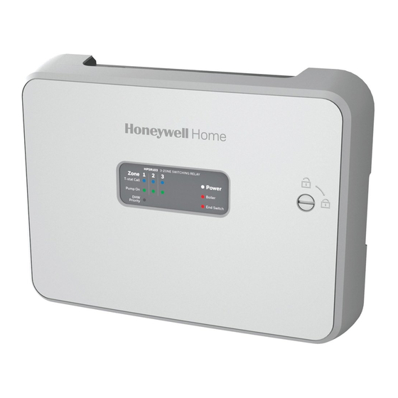
HONEYWELL HYDRONIC PRO
SWITCHING RELAY PANEL
PANEL SPECIFICATIONS
Model
Zones Transformers
HPSR103
3
(1) 24V 40VA
HPSR104
4
(1) 24V 40VA
HPSR106
6
(1) 24V 40VA
NOTES:
• All circulator relay connections, including ZC/ZR, are rated for 5A full load and 30A locked rotor (1/6 to 1/2HP
depending on technology) at 120VAC. Check circulator plate ratings to ensure full load current is not exceeded.
• End switch connections are rated 24V, 1 Amp.
• All thermostat connections supply a 24V Class 2 output.
WHAT'S IN THE BOX?
• Hydronic Zone Panel
• Mounting Hardware (3 Screws and 3 Wall Anchors)
• 1, 2-Amp Fuse; 1, 6-Amp Fuse
• Install Manuals (English & French)
Table 1.
Maximum
Input Power
Combined
Load
120VAC, 60Hz, 1
15 amps
120VAC, 60Hz, 1
20 amps
120VAC, 60Hz, 1
20 amps
INSTALLATION INSTRUCTIONS
CAUTION
1. Disconnect power supply before beginning
installation to prevent electrical shock or
equipment damage.
2. Use copper conductors only.
3. Use only NEC Class 1 wire for all line voltage
wiring connections. Class 1 wires must be
rated for at least 167 °F (75 °C).
4. For installation by professionals only.
Priority
Pump
Zone
Fuse
Width
Control
6 Amp
Yes
11-3/4"
6 Amp
Yes
11-3/4"
6 Amp
Yes
11-3/4"
Type 1 Enclosure
Height
Depth
8-3/4"
2-1/8"
8-3/4"
2-1/8"
8-3/4"
2-1/8"
33-00331EF-05
Advertisement
Table of Contents

Related Manuals for Honeywell HPSR103


Summary of Contents for Honeywell HPSR103
- Page 1 HPSR10* HONEYWELL HYDRONIC PRO SWITCHING RELAY PANEL INSTALLATION INSTRUCTIONS WHAT'S IN THE BOX? • Hydronic Zone Panel • Mounting Hardware (3 Screws and 3 Wall Anchors) • 1, 2-Amp Fuse; 1, 6-Amp Fuse • Install Manuals (English & French) CAUTION 1.
-
Page 2: Hang Hole Flow
HPSR10* MOUNTING Din Rail Flow 1. Mount the DIN rail as per manufacturers instruc- Hang Hole Flow tions. 1. Hang the panel on a wall-mounted screw. M37086 Fig. 4. 2. Hang panel by the tabs on the rail’s top edge. M37083 Fig. -
Page 3: Wiring And Setup
HPSR10* WIRING AND SETUP Priority Override Honeywell Hydronic Panels support priority operation and Power Input can be enabled with the use of a switch located in the top right section of the panel labeled "Priority Zone". Honeywell Hydronic Panels include a convenient wiring terminal for wiring 120V/60Hz/1Ph power. -
Page 4: Standard Wiring Layout
HPSR10* Standard Wiring Layout Below wiring diagrams represent a 6 zone pump panel and a 4 zone pump panel. Wiring diagram for the 3 zone pump panel is identical to the 4 zone pump panel but with zone 4 depopulated. THERMOSTAT WIRING THERMOSTAT WIRING TO BOILER... -
Page 5: Boiler Controls
HPSR10* Boiler Controls Honeywell Hydronic Panels are capable of managing boilers with DHW priority. The panel features two isolated end switches labeled Boiler and End Switch for TT outputs to the boiler. Two slide switches are available to provide simple programing of the end switches to meet the desired application. -
Page 6: Troubleshooting
Honeywell shall repair or replace it (at Honeywell's option). This warranty does not cover removal or reinstallation costs. This warranty shall not apply if it is shown by Honeywell that the defect was caused by damage which occurred while the product was in the possession of a consumer. -
Page 7: Contenu De L'emballage
HPSR10* PANNEAU DE RÉGULATEURS DE POMPES HYDRONIQUE PRO HONEYWELL INSTRUCTIONS D’INSTALLATION CONTENU DE L’EMBALLAGE • Panneau de régulateurs de pompes de zone hydronique • Quincaillerie de montage (3 vis et 3 ancrages muraux) • 1 fusible de 2 A; 1 fusible de 6 A •... -
Page 8: Montage
HPSR10* MONTAGE Rail DIN 1. Montez le rail DIN conformément aux instructions Trou de suspension du fabricant. 1. Accrochez le panneau à une vis fixée au mur. M37086 Fig. 4. 2. Suspendez le panneau par les languettes sur le bord supérieur du rail. -
Page 9: Câblage Et Configuration
40 VA par transformateur ne soit pas dépassée. En outre, les panneaux hydroniques Honeywell sont compatibles avec les modules d’interface de l’équipement Honeywell dans les installations ne disposant pas de suffisamment de câblage. R : 24 V (généralement rouge) W : Chauffage (généralement blanc) R W C C : Commun (généralement bleu) -
Page 10: Disposition Standard Du Câblage
HPSR10* Disposition standard du câblage Les schémas de câblage ci-dessous représentent un panneau de régulateurs de pompes à 6 zones et un à 4 zones. Les schémas de câblage pour le panneau à 3 zones est similaire à celui à 4 zones. CÂBLAGE DU THERMOSTAT CÂBLAGE DU THERMOSTAT VERS LA CHAUDIÈRE... -
Page 11: Contrôles De La Chaudière
Contrôles de la chaudière Les panneaux hydroniques Honeywell permettent de gérer les chaudières avec une priorité pour l’ECS. Le panneau est doté de deux interrupteurs d’extrémité isolés marqués « Chaudière » et « Interrupteur d’extrémité » pour les sorties TT vers la chaudière. -
Page 12: Dépannage
GARANTIE LIMITÉE DE 5 ANS Honeywell garantit ce produit contre tout vice de fabrication ou de matériau dans la mesure où il en est fait une utilisation et un entretien convenables, et ce, pour cinq (5) ans à partir de la date d’achat par le consommateur. En cas de défaillance ou de mauvais fonctionnement pendant la période de garantie, Honeywell remplacera ou réparera le produit (à...