
Related Manuals for Raritan DRX Series

Summary of Contents for Raritan DRX Series
- Page 1 Environmental Sensors and Actuators Guide Revision 1C Copyright © 2018 Raritan, Inc. SENSOR-1C-v3.4.20-E August 2018 255-90-0003-00...
- Page 2 Raritan, Inc. © Copyright 2018 Raritan, Inc. All third-party software and hardware mentioned in this document are registered trademarks or trademarks of and are the property of their respective holders.
-
Page 3: Table Of Contents
Contents What's New in the Environmental Sensors and Actuators Guide Products Supporting Raritan Sensor Packages viii Chapter 1 Introduction to Environmental Sensor Packages Sensor Overview ..........................2 Sensor Comparison .......................... 3 Sensor Support Guidelines....................... 3 Chapter 2 DX2 Series ... - Page 4 Contents Adjusting Dip Switches ........................38 Chapter 4 DPX3 Series Available DPX3 Sensor Packages ....................39 DPX3 Temperature and Humidity Sensors ..................40 DPX3 LED States ........................41 Cascading DPX3 Sensor Packages ....................41 Chapter 5 DPX2 Series ...
- Page 5 Contents Chapter 7 Sensor-Mixing Connections Cascading DX2, DX and DPX3 Sensor Packages................68 Mixing DPX, DPX2, DPX3, DX and DX2 Sensor Packages .............. 69 Appendix A Supported Maximum Sensor Distance Appendix B Supported Maximum Number of Sensors and Actuators ...
- Page 6 Sensors and Actuators Guide The following sections have changed or information has been added to the Environmental Sensors and Actuators Guide based on enhancements to the Raritan environmental sensor packages and/or user documentation. Products Supporting Raritan Sensor Packages (on page viii)
- Page 7 What's New in the Environmental Sensors and Actuators Guide Sensor-Mixing Connections (on page 68) Cascading DX2, DX and DPX3 Sensor Packages (on page 68) Mixing DPX, DPX2, DPX3, DX and DX2 Sensor Packages (on page 69) Supported Maximum Number of Sensors and Actuators (on page 77) Sensor Measurement Accuracy (on page 78)
- Page 8 Products Supporting Raritan Sensor Packages The following products support Raritan environmental sensor packages. Sensor Support Guidelines For detailed information, see (on page 3). Raritan products: PX2 series power distribution units (PDUs) PX3 series PDUs, including PX3-iX7 EMX asset management devices ...
-
Page 9: Chapter 1 Introduction To Environmental Sensor Packages
DPX3, DX and DX2 series. DPX series is the first generation while DX2 series is the latest generation. For a list of Raritan and Legrand products that support all of Raritan's Products Supporting Raritan Sensor Packages sensor packages, see (on page viii). -
Page 10: Sensor Overview
Number of supported sensors/actuators per Raritan/Legrand product: A sensor port on a Raritan or Legrand product, such as a PDU, can support up to 32 sensors or actuators. For information on how to count Supported Maximum Number of the number of sensors/actuators, see Sensors and Actuators (on page 77). -
Page 11: Sensor Comparison
* Chain position availability column indicates whether a sensor's position in a sensor daisy chain is available or not. This information is retrievable from the Raritan or Legrand product where the sensor is connected, such as PX3 or Legrand PDU. -
Page 12: Chapter 2 Dx2 Series
With standard network patch cables, you can: Connect a DX2 sensor to a Raritan or Legrand product with the "RJ-45" SENSOR port, such as PX3 or Legrand PDU. Exception: For a Raritan PDU or EMX with an "RJ-12" SENSOR port, an RJ-12 to RJ-45 adapter cable (part number: RJ12M-RJ45M) is needed, which you can request from Raritan. -
Page 13: Available Dx2 Sensor Packages
Raritan has developed 3 generations of contact closure sensors: DPX-CC2-TR, DX series and DX2 series. Choose the type that satisfies your needs. The newest one is DX2-CC2. Note that only DPX-CC2-TR supports Raritan's water sensors while DX and DX2 contact closure sensors do NOT support them. -
Page 14: Dx2-Dh2C2 Door Handle Controller
DX2-DH2C2 provides a cabinet access control solution. All you need to do is simply connect supported door handles to DX2-DH2C2, then connect DX2-DH2C2 to Raritan's PX3, PX3TS or Legrand PDU, and finally you will be able to control a cabinet's door handles via PX3, PX3TS or Legrand PDU. - Page 15 Chapter 2: DX2 Series Note: Raritan provides SmartLock kits that include both DX2-DH2C2 and one of the listed door handles. For more information on SmartLock kits, refer to the user documentation accompanying the SmartLock kit or download it from Raritan's Support page http://www.raritan.com/support/...
-
Page 16: Bracket Installation
Chapter 2: DX2 Series Number Component Function The two door handles are usually attached to different doors of the same cabinet. Two pairs of Connect to contact closure sensors for detecting the contact closure door open/closed status. sensor terminals For information on connecting CC sensors, see Connecting Detectors/Switches to DX2-CC2 page 13). -
Page 17: Dx2 Temperature And Humidity Sensors
Two RJ-45 ports Connect a standard network patch cable for either or both purposes below: Connect to the SENSOR port of a Raritan product (like a PX3 PDU) or Legrand PDU. Cascade DX2 sensor package(s). Cascading DX2 Sensor Packages (on page 17). -
Page 18: Dx2 Led States
States (on page 10). Tip -- other generations of temperature and humidity sensors: Raritan has developed 4 generations of humidity and temperature sensors. Choose the type that satisfies your needs. The newest generation is DX2 series. For the other generations, see: ... -
Page 19: Dx2-Cc2 Contact Closure Sensors
Description High-speed flashing Sensor firmware is being updated. DX2-CC2 Contact Closure Sensors Raritan's contact closure sensor can detect the open-and-closed status of connected detectors/switches. There are two channels for connecting two discrete detectors/switches (state: on/off). Four termination points are available on this sensor: the two to the right are associated with one channel, and the two to the left are associated with the other. - Page 20 2. Connect DX2-CC2 to a Raritan or Legrand product that supports Raritan sensor packages, such as Raritan's PX3 or Legrand PDU. 3. Log in to the application of Raritan or Legrand product where DX2-CC2 is being connected, and configure Normally Open or...
-
Page 21: Connecting Detectors/Switches To Dx2-Cc2
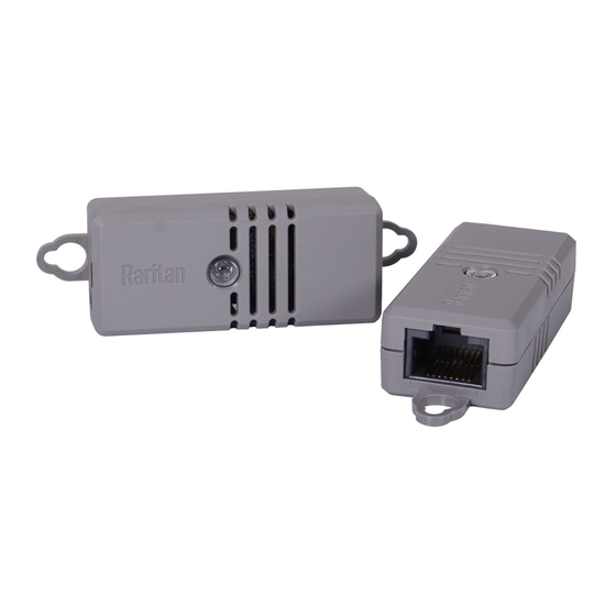
Chapter 2: DX2 Series Configuring DX2-CC2's Normal State (on page 15). Connecting Detectors/Switches to DX2-CC2 DX2-CC2 comprises two parts: sensor box and terminal module. The terminal module is detachable so it is convenient to connect/disconnect discrete detectors/switches. To make connections when the terminal module is attached: 1. - Page 22 Chapter 2: DX2 Series 3. Use a screwdriver with a 2.5 mm wide shaft to tighten the screws above each termination point to secure the wires, using a torque of 0.196 N·m (2 kgf·cm). To make connections after the terminal module is separated: You can also connect a detector/switch when the terminal module is separated from the sensor box.
-
Page 23: Configuring Dx2-Cc2'S Normal State
DX2-CC2 via the software application of the Raritan or Legrand product where this DX2-CC2 is being connected. To determine the normal state of DX2-CC2: 1. Log in to the web interface of the Raritan or Legrand product where DX2-CC2 is being connected. 2. Do the following. -
Page 24: Dx2-Cc2 Contact Closure Sensor Leds
DX2-CC2 is connected. For details, refer to the user guide or online help of your Raritan or Legrand product. DX2-CC2 Contact Closure Sensor LEDs LED description in this section applies to all of Raritan's contact closure sensors, including DPX-CC2-TR, DX series and DX2-CC2. See Available DX Sensor Packages... -
Page 25: Cascading Dx2 Sensor Packages
1. Connect a standard network patch cable to either RJ-45 port of the first DX2 sensor package. Exception: For a Raritan PDU or EMX with an "RJ-12" SENSOR port, an RJ-12 to RJ-45 adapter cable (part number: RJ12M-RJ45M) is needed, which you can request from Raritan. - Page 26 Chapter 2: DX2 Series Exception: You CANNOT cascade DX2-DH2C2 packages. For details, (on page 6). DX2-DH2C2 Door Handle Controller 3. Make sure the total number of sensors and actuators connected to these DX2 packages does not exceed 32 per sensor port. See Supported Maximum Number of Sensors and Actuators (on page 77).
-
Page 27: Chapter 3 Dx Series
With a standard network patch cable (CAT5e or higher), you can: Connect a DX sensor to a Raritan or Legrand product with the RJ-45 SENSOR port, such as Raritan's PX3 PDU or Legrand PDU. Exception: For a Raritan PDU or EMX with an "RJ-12" SENSOR port, an RJ-12 to RJ-45 adapter cable (part number: RJ12M-RJ45M) is needed, which you can request from Raritan. -
Page 28: Available Dx Sensor Packages
Chapter 3: DX Series Available DX Sensor Packages Sensor packages Description 7 pairs of terminals: DX-D2C6 2 for connecting dry contact signal actuators (DC). 5 for connecting contact closure sensors (CC). 1 hall effect sensor Note: The hall effect sensor is reserved for future use and currently shall NOT be used. -
Page 29: Dx-D2C6
DPX-CC2-TR, DX series and DX2 series. Choose the type that satisfies your needs. The newest one is DX2-CC2. Note that only DPX-CC2-TR supports Raritan's water sensors while DX and DX2 contact closure sensors do NOT support them. For the other generations, see: ... - Page 30 The hall effect sensor is reserved for future use and currently shall NOT be used. After connecting DX-D2C6 to a Raritan PDU or EMX, this built-in sensor will be detected and show up in that PDU or EMX web interface and SNMP MIB, which is normal.
- Page 31 Chapter 3: DX Series Numbers Components Dip switch 2 controls CC3. Dip switch 3 controls CC4. Dip switch 4 controls CC5. Bottom row: Dip switch 1 controls CC1. Dip switch 2 controls the built in hall effect sensor. Tip: If an alert is shown for this hall effect sensor, you can disable it by turning on/off dip switch 2.
-
Page 32: Dx-Pd2C5
Chapter 3: DX Series DX-PD2C5 DX-PD2C5 is physically similar to DX-D2C6 except for the following differences: Dry contact signal channels of DX-PD2C5 supply DC 12V power to the connected actuators. Dry contact signal channels of DX-PD2C5 only support the connection of EMKA (1150-U5x) door handles. - Page 33 Chapter 3: DX Series DX-PD2C5 terminals, dip switches, and LEDs: Terminals, dip switches, and LEDs are separated into two rows as shown below. Numbers Components CC and PDC channels. Top row: Four CC channels (CC2 - CC5). Two PDC channels (PDC1 - PDC2). ...
- Page 34 Chapter 3: DX Series Numbers Components Note: Dip switch 2 in the bottom row does not control any channel and can be ignored. CC status LEDs. For details, see DX2-CC2 Contact Closure Sensor LEDs (on page 16). High-speed flashing of CC1 LED indicates that the DX Sensor Firmware firmware upgrade is in progress.
-
Page 35: Dx-Pir
Chapter 3: DX Series DX-PIR DX-PIR contains one occupancy sensor (that is, presence detector), one tamper sensor and a pair of terminals for connecting a contact closure (CC) sensor. Occupancy sensor: The occupancy sensor is located on the top of the DX-PIR. It uses the passive infrared technology to detect the motion of a person by sensing the temperature differences between a person and the surroundings. - Page 36 Chapter 3: DX Series Side View Top View Maximum range: 5 meters Maximum range: 5 meters Vertical sensing area: 82 degrees Horizontal sensing area: 94 degrees (+/- 41 degrees) (+/- 47 degrees) Conditions for the detected target: ...
-
Page 37: Dx-D4C3
Chapter 3: DX Series DX-PIR Terminals, dip switches and LED: Numbers Components One CC channel comprising a pair of terminals. Connecting Detectors/Actuators to DX (on page 34) for how to connect a CC sensor. Dip switch 1 configures the Normal state of the CC channel. - Page 38 Chapter 3: DX Series The label attached to DX-D4C3 helps you identify each channel. DX-D4C3 Label: CC represents a contact closure sensor channel. There are three CC channels: CC1 through CC3. DC represents a dry contact signal actuator channel. There are four DC channels: DC1 through DC4.
- Page 39 Chapter 3: DX Series Numbers Components Dip switch 1 controls CC2. Dip switch 2 controls CC3. Bottom row: Dip switch 1 controls CC1. Note: Dip switches 3 and 4 in the top row and dip switch 2 in the bottom row do not control any channel and can be ignored.
-
Page 40: Dx-Vbr
Chapter 3: DX Series DX-VBR DX-VBR contains one vibration sensor and a pair of terminals for connecting a contact closure (CC) sensor. Vibration sensor: The built-in vibration sensor detects the vibration of any object where DX-VBR is affixed. The sensor determines the vibration by measuring the accelerations in three mutually perpendicular directions, and then generating a numeric value representing the magnitude of the acceleration due to gravity of the Earth. - Page 41 Chapter 3: DX Series DX-VBR Terminals, dip switches and LED: Numbers Components One CC channel comprising a pair of terminals. Connecting Detectors/Actuators to DX (on page 34) for how to connect a CC sensor. Dip switch 1 configures the Normal state of the CC channel.
-
Page 42: Making Connections
Chapter 3: DX Series Making Connections Pre-installed DX Brackets To allow you to hang or affix a DX onto an object or position, two brackets have been installed on the rear side of a DX sensor package when shipped out of the factory. Below is the diagram of a DX sensor package with two brackets installed. - Page 43 Chapter 3: DX Series Important: For a PDC channel, you must check the electrical polarity markings (+ and -) on the DX label to make sure each wire is inserted into the correct termination point with the correct polarity. 3. Use a screwdriver with a 2.5 mm wide shaft to tighten the screws above each termination point to secure the wires, using a torque of 0.196 N·m (2 kgf·cm).
-
Page 44: Cascading Dx Sensor Packages
Chapter 3: DX Series 2. Separate the terminal module from the sensor box. 3. After connecting detectors/switches to the terminal module, plug the terminal module back into the sensor box, and then tighten the screws at two sides of the terminal module. Cascading DX Sensor Packages To increase the number of connected DX sensor packages per SENSOR port, you can cascade DX using standard network patch cables (CAT5e or... - Page 45 1. Connect a standard network patch cable to either RJ-45 port of the first DX sensor package. Exception: For a Raritan PDU or EMX with an "RJ-12" SENSOR port, an RJ-12 to RJ-45 adapter cable (part number: RJ12M-RJ45M) is needed, which you can request from Raritan.
-
Page 46: Adjusting Dip Switches
Chapter 3: DX Series Adjusting Dip Switches There are two Normal settings for each CC channel on DX packages. N.O (Normally Open): The open status of the connected detector/switch is considered normal. An alarm is triggered when the detector/switch turns closed. ... -
Page 47: Chapter 4 Dpx3 Series
With a standard network patch cable (CAT5e or higher), you can: Connect a DPX3 sensor to a Raritan or Legrand product with the "RJ-45" SENSOR port, such as Raritan's PX3 PDU or Legrand PDU. Exception: For a Raritan PDU or EMX with an "RJ-12" SENSOR port, an RJ-12 to RJ-45 adapter cable (part number: RJ12M-RJ45M) is needed, which you can request from Raritan. -
Page 48: Dpx3 Temperature And Humidity Sensors
States (on page 41). Tip -- other generations of temperature and humidity sensors: Raritan has developed 4 generations of humidity and temperature sensors. Choose the type that satisfies your needs. The newest generation is DX2 series. For the other generations, see: ... -
Page 49: Dpx3 Led States
1. Connect a standard network patch cable to either RJ-45 port of the first DPX3 sensor package. Note: For a Raritan EMX or PDU with the "RJ-12" SENSOR port, use the RJ-12 to RJ-45 adapter cable instead. 2. If you want to cascade DPX3 sensor packages, get an additional... - Page 50 Chapter 4: DPX3 Series a. Plug one end of the cable into the remaining RJ-45 port on the prior DPX3. b. Plug the other end into either RJ-45 port on an additional DPX3. Repeat the same steps to cascade more DPX3 sensor packages. 3.
-
Page 51: Chapter 5 Dpx2 Series
Individual DPX2 sensors can be replaced without the need to re-connect the DPX2 sensor cable. DPX2 series works with Raritan's DPX3 sensor hub 'DPX3-ENVHUB4', but with the DPX sensor hub 'DPX-ENVHUB4'. DPX2 can be connected to the end of a DX2, DX, or DPX3 sensor chain while DPX sensor packages CANNOT. -
Page 52: Available Dpx2 Sensor Packages
Chapter 5: DPX2 Series Available DPX2 Sensor Packages Sensor packages Description 1 temperature sensor DPX2-T1 DPX2 Temperature and Humidity Sensors (on page 45). 1 temperature sensor DPX2-T1H1 1 humidity sensor DPX2 Temperature and Humidity Sensors (on page 45). ... -
Page 53: Dpx2 Temperature And Humidity Sensors
DX2 LED States (on page 10). Tip -- other generations of temperature and humidity sensors: Raritan has developed 4 generations of humidity and temperature sensors. Choose the type that satisfies your needs. The newest generation is DX2 series. For the other generations, see: ... -
Page 54: Connection And Disconnection
Chapter 5: DPX2 Series Connection and Disconnection Before connecting a DPX2 sensor to a Raritan or Legrand product, you must connect it to a DPX2 sensor cable first. If any connected sensor is broken, you can replace it with a new one without disconnecting the DPX2 sensor cable from the Raritan or Legrand product. - Page 55 Chapter 5: DPX2 Series Sensor connection guidelines: Always make sure there are NO free head connectors between the sensor cable's RJ-12 connector and the final DPX2 sensor attached to it. That is, each head connector prior to the final DPX2 sensor must be occupied with a sensor.
-
Page 56: Disconnecting A Dpx2 Sensor
Chapter 5: DPX2 Series Disconnecting a DPX2 Sensor You can remove any individual DPX2 sensor from the sensor cable whenever needed. To disconnect a DPX2 sensor: 1. Press the latch of the cable connector so that the other side of the latch slightly goes up. -
Page 57: Connecting A Dpx2 Sensor Package To Dx2, Dx Or Dpx3
Chapter 5: DPX2 Series Connecting a DPX2 Sensor Package to DX2, DX or DPX3 You can connect one DPX2 sensor package to the "end" of a DX2, DX or DPX3 sensor chain. It is strongly recommended to use an RJ-12 to RJ-45 adapter for connecting the DPX2 to the final DX2, DX or DPX3 in the chain. - Page 58 Chapter 5: DPX2 Series When connecting a DPX2 sensor package containing "one" DPX2 sensor: A maximum of eleven DX sensor packages can be cascaded because 12-1=11.
-
Page 59: Chapter 6 Dpx Series
DPX is the first generation of Raritan environmental sensor packages. Most DPX packages come with a factory-installed sensor cable with an "RJ-12" connector. DPX supports the use of a Raritan sensor hub to increase the number of connected DPX sensors. In This Chapter Available DPX Sensor Packages ............... -
Page 60: Available Dpx Sensor Packages
Chapter 6: DPX Series Available DPX Sensor Packages Sensor packages Description 1 temperature sensor DPX-T1 DPX Temperature and Humidity Sensors page 53). 1 temperature sensor DPX-T1H1 1 humidity sensor DPX Temperature and Humidity Sensors page 53). 3 temperature sensors DPX-T3H1 ... -
Page 61: Dpx Temperature And Humidity Sensors
Chapter 6: DPX Series DPX Temperature and Humidity Sensors Raritan provides three types of DPX temperature and humidity sensor DPX-T1 DPX-T1H1 DPX-T3H1 packages: A DPX-T3H1 package contains one DPX-T1H1 and two DPX-T1 sensors. As shown in the following diagram, all sensors have been connected to the sensor cable, when shipping out of the factory, in a manner that you cannot remove or replace any individual sensor. -
Page 62: Dpx Air Flow Sensors
Chapter 6: DPX Series DPX Air Flow Sensors If a DPX air flow sensor (DPX-AF1) is connected, make sure the sensor faces the source of the wind (such as a fan) in the appropriate orientation as indicated by the arrow on that sensor. To affix this sensor to an object or place, just screw it up using the sensor's two screw holes. -
Page 63: Connecting Tubes
Chapter 6: DPX Series Number Component Description 'In' port Connect to a Raritan or Legrand product. (RJ-12) If cascading multiple air pressure sensors, connect this port to the 'Out' port of another sensor. 'Out' port Use this port for cascading air pressure sensors. -
Page 64: Connecting A Dpx Sensor Package To An Air Pressure Sensor
Plug the other end into a Raritan or Legrand product's sensor port. An RJ-12 to RJ-45 adapter is required if your Raritan PDU has an RJ-45 SENSOR port, such as PX3. 2. Connect one DPX sensor package to the air pressure sensor's "Out"... -
Page 65: Dpx Contact Closure Sensors
Door lock detection Smoke detection Vibration detection However, Raritan produces floor water sensors, which can be connected DPX Floor Water Sensors to and work with DPX-CC2-TR. See (on page 63). When using third-party probes, you must test them with DPX-CC2-TR to ensure they work properly. - Page 66 Failure to follow installation and configuration instructions can result in false alarms or no alarms. Raritan makes no statement or claim that all third-party detectors/switches will work with Raritan's contact closure sensors.
-
Page 67: Connecting Detectors/Switches To Dpx-Cc2-Tr
Chapter 6: DPX Series Connecting Detectors/Switches to DPX-CC2-TR DPX-CC2-TR comprises two parts: sensor box and terminal module. The terminal module is detachable so it is convenient to connect/disconnect discrete detectors/switches. Below are the resistance values for DPX-CC2-TR to open and close a connected detector/switch reliably. - Page 68 Chapter 6: DPX Series 3. Use a screwdriver with a 2.5 mm wide shaft to tighten the screws above each termination point to secure the wires, using a torque of 0.196 N·m (2 kgf·cm). To make connections after the terminal module is separated: You can also connect a detector/switch when the terminal module is separated from the sensor box.
-
Page 69: Configuring A Dpx Contact Closure Sensor
Chapter 6: DPX Series 3. After connecting detectors/switches to the terminal module, plug the terminal module back into the sensor box, and then tighten the screws at two sides of the terminal module. Configuring a DPX Contact Closure Sensor Before using DPX-CC2-TR to detect contact closure status, water, smoke or vibration, you must determine the normal state by adjusting its dip switch. -
Page 70: Contact Closure Sensor Leds
DX2-CC2 Contact Closure Sensor LEDs (on page 16). Proper LED behaviors of DPX water sensors: For Raritan's DPX water sensors, the Normal state must be set to Normally Open (N.O). The following is the correct LED behavior based on proper dip switch settings. -
Page 71: Dpx Floor Water Sensors
Note that only the DPX-CC2-TR support these water sensors. Other Raritan contact closure sensor packages do not support them. Note: If you order a Raritan DPX water sensor with the part number containing the suffix -KIT, you get the DPX-CC2-TR, which supports it. - Page 72 Chapter 6: DPX Series Number Item Wires to connect to the contact closure sensor. You need a minimum of 30 cm wires to prevent the contact closure sensor from being damaged by floor water (if any). Below are the wire length limitations: ...
-
Page 73: Cable Water Sensor
The cable water sensor is in the shape of a cable so it can be flexibly placed, twisted or wrapped around a location where water may drip, such as a ceiling tile, water pipe or the floor. Raritan provides two types of cable water sensors. The only difference is their cable length. ... - Page 74 Chapter 6: DPX Series How a Cable Water Sensor Works The cable water sensor uses black wires on the water rope to detect the water. When there is water between two black wires, it causes current loop back to trigger the alarm on the water sensor. Mechanical information about black wires: ...
- Page 75 Chapter 6: DPX Series The alarm requires some water between two black wires for a while. If there are just few water drops on the cable water sensor, no alarms are triggered. The water sensor's rope should be mounted on the floor firmly, or the water sensor cannot detect the water.
-
Page 76: Chapter 7 Sensor-Mixing Connections
Raritan or Legrand product. Other sensor-mixing connections than those shown in this chapter are NOT supported. Make sure your Raritan and Legrand products have been upgraded to version 3.4.20 or later to support these sensor-mixing combinations. -
Page 77: Mixing Dpx, Dpx2, Dpx3, Dx And Dx2 Sensor Packages
Chapter 7: Sensor-Mixing Connections The daisy chain procedure is identical to the one described any topic below: Cascading DX2 Sensor Packages (on page 17) Cascading DX Sensor Packages (on page 36) Cascading DPX3 Sensor Packages (on page 41) Same as a pure DX2, DX or DPX3 sensor chain, you can replace the final Connecting a DPX2 sensor package with a DPX2 sensor package. - Page 78 Chapter 7: Sensor-Mixing Connections One individual DPX3 sensor package A chain of DPX3 sensor packages One individual DPX2 sensor package One individual DPX sensor package...
- Page 79 Chapter 7: Sensor-Mixing Connections An RJ-12 to RJ-45 adapter is recommended to connect a DPX or DPX2 sensor package to DPX3-ENVHUB4. In the following diagrams, the sensor package in "green" can be replaced by a DPX2 sensor package. The sensor package in "blue" can be one DPX2, DPX3, DX or DX2 sensor package.
- Page 80 Chapter 7: Sensor-Mixing Connections...
- Page 81 Chapter 7: Sensor-Mixing Connections Sensor mixing with DX2, DX and DPX3 in a chain: In the above diagrams, any DPX3 sensor package can be replaced by a DX2 or DX sensor package, or vice versa. If intended, you can also mix DX2, DX and DPX3 sensor packages in a Cascading DX2, DX and DPX3 Sensor Packages sensor chain.
-
Page 82: Appendix A Supported Maximum Sensor Distance
Appendix A Supported Maximum Sensor Distance General DX2, DX, DPX2 and DPX3 sensor packages: DPX2, DPX3, DX and DX2 sensor package support the total cabling length up to 98 feet (30 meters), except for DX-PD2C5 and DX2-DH2C2. Exception -- DX2-DH2C2 and DX-PD2C5: DX2-DH2C2 and DX-PD2C5 support a maximum cabling length of 29 feet (9 meters) instead of 98 feet (30 meters). - Page 83 DPX3-ENVHUB4 supports all Raritan sensor packages, including DPX, DPX2, DPX3, DX and DX2. Each sensor port on a Raritan or Legrand product, such as a PDU, supports only one Raritan sensor hub so DO NOT cascade sensor hubs. DPX series: DPX series' supported distance is determined by the length of the sensor cable pre-installed (or provided) by Raritan.
- Page 84 Appendix A: Supported Maximum Sensor Distance Raritan or 33 feet 1 DPX-ENVHUB4 16 feet Up to 4 Legrand product, (10 m) (5 m) DPX-T3H1 such as a PDU sensor packages...
-
Page 85: Appendix B Supported Maximum Number Of Sensors And Actuators
Sensors and Actuators The maximum number of sensors and actuators that can be managed per sensor port of a Raritan product or Legrand PDU is 32 sensors or actuators. Note that though Raritan's EMX2-888 has 8 sensor ports, the number of "externally-connected"... -
Page 86: Appendix C Sensor Measurement Accuracy
Appendix C Sensor Measurement Accuracy This section shows the factory specifications of Raritan DPX, DPX2 and DX2 environmental sensor packages. Calibration is not required for these sensor packages. In This Chapter DPX Sensor Accuracy ................78 DPX2 Sensor Accuracy ................78 DX2 Sensor Accuracy ................ -
Page 87: Appendix D Sensor Firmware Update
DPX2, DPX3, DX and DX2 sensor packages automatically upgrade or downgrade their firmware after being connected to a Raritan or Legrand PDU or a Raritan EMX that supports these sensor packages. This way it ensures that these sensor packages work properly with the connected PDU or EMX. -
Page 88: Appendix E Sensor Naming Conventions
Appendix E Sensor Naming Conventions The model name of a Raritan environmental sensor package consists of sensor family, sensor functions and the total number of the specified functions. [Family] - [Function_1] [Number_1] - OR - [Family] - [Function_1] [Number_1] [Function_2] [Number_2] [Family] is DPX, DPX2, DPX3, DX or DX2. - Page 89 Appendix E: Sensor Naming Conventions Abbreviations Functions Floor-mounted water sensors...
- Page 90 Index A D Adjusting Dip Switches • 22, 25, 29, 30, 33, 38 Disconnecting a DPX2 Sensor • 48 Available DPX Sensor Packages • 2, 52, 56 DPX Air Flow Sensors • 52, 54 Available DPX2 Sensor Packages • 2, 44 DPX Contact Closure Sensors •...
-
Page 91: Index
Mixing DPX, DPX2, DPX3, DX and DX2 Sensor Packages • vii, 69 P Pre-installed DX Brackets • 34 Products Supporting Raritan Sensor Packages • vi, viii, 1, 3 S Sensor Comparison • vi, 3 Sensor Firmware Update • vii, 10, 23, 26, 29, 31, 33, 79 Sensor Measurement Accuracy •...