
Related Manuals for Lenovo V530S-07ICB


Summary of Contents for Lenovo V530S-07ICB
- Page 1 V530S-07ICB User Guide and Hardware Maintenance Manual Energy Star Machine Types: 10TX, 10TY, 10XV, and 10XW...
- Page 2 Important Product Information Guide and Appendix A “Notices” on page 47. First Edition (July 2018) © Copyright Lenovo 2018. LIMITED AND RESTRICTED RIGHTS NOTICE: If data or software is delivered pursuant to a General Services Administration “GSA” contract, use, reproduction, or disclosure is subject to restrictions set forth in Contract No. GS-...
-
Page 3: Table Of Contents
Replacing the storage drive ..Appendix B. Trademarks ..49 Replacing the card reader ... © Copyright Lenovo 2018... - Page 4 V530S-07ICB User Guide and Hardware Maintenance Manual...
-
Page 5: Chapter 1. Overview
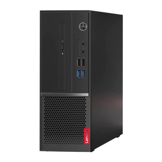
USB 3.1 Gen 1 connectors (2) USB 3.1 Gen 2 connectors (2) Optical drive eject/close button Used to eject the tray of the optical drive. After you insert a disc into the tray, press the eject/close button to close the tray. © Copyright Lenovo 2018... - Page 6 Used to connect a USB-compatible device. For optimal data transfer, connect a USB 3.1 Gen 2 device to a USB 3.1 Gen 2 connector instead of a USB 3.1 Gen 1 or USB 2.0 connector. V530S-07ICB User Guide and Hardware Maintenance Manual...
-
Page 7: Rear View
Rear view Note: Your computer model might look slightly different from the illustration. Figure 2. Rear view Audio line-out connector HDMI 1.4 out connector ® DisplayPort 1.2 out connector VGA-out connector USB 2.0 connectors (2) USB 3.1 Gen 1 connectors (2) Power cord connector Serial connector Ethernet connector... - Page 8 Used to secure a padlock. Security-lock slot Used to secure a Kensington-style cable lock. Serial connector Used to connect an external modem, a serial printer, or other devices that use a serial connector. PCI-Express card area V530S-07ICB User Guide and Hardware Maintenance Manual...
-
Page 9: System Board
To improve the operating performance of the computer, you can connect PCI-Express cards into this area. Depending on the computer model, the connectors in this area vary. System board Note: See “Front view” and “Rear view” for additional component descriptions. Figure 3. -
Page 10: Machine Type And Model Label
Machine type and model label The machine type and model label identifies the computer. When you contact Lenovo for help, the machine type and model information helps support technicians to identify the computer and provide faster service. The machine type and model label is attached on the computer as shown. -
Page 11: Chapter 2. Specifications
• USB connectors Expansion • Card reader • Memory slots • Optical drive (optional) • PCI Express x1 card slot • PCI Express x16 graphics card slot • Storage drive bay Network features • Ethernet LAN © Copyright Lenovo 2018... - Page 12 • Bluetooth (optional) Physical dimensions • Width: 100.0 mm (3.9 inches) • Height: 274.8 mm (10.8 inches) • Depth: 304.4 mm (12.0 inches) Weight (without the package) Maximum configuration as shipped: 4.2 kg (9.3 lb) V530S-07ICB User Guide and Hardware Maintenance Manual...
-
Page 13: Chapter 3. Computer Locks
Depending on the type selected, the cable lock can be operated with a key or a combination. The cable lock also locks the buttons used to open the computer cover. This is the same type of lock used with many notebook computers. You can order such a cable lock directly from Lenovo by searching for Kensington at: http://www.lenovo.com/support... - Page 14 2. Pull the cables you want to lock through the dents in the smart cable clip. 3. Press the clip into the cable-lock slot until it snaps into position. Figure 7. Attaching a smart cable clip V530S-07ICB User Guide and Hardware Maintenance Manual...
-
Page 15: Chapter 4. Replacing Hardware
• When installing or replacing an option, use the appropriate instructions explained in this manual along with the instructions that come with the option. • In most areas of the world, Lenovo requires the return of defective CRUs. Information about this will come with the CRU or will come a few days after the CRU arrives. -
Page 16: Locating Frus (Including Crus)
Locating FRUs (including CRUs) Notes: • Some of the following components are optional. • To replace a component that is not in the list below, contact a Lenovo service technician. For a list of Lenovo Support phone numbers, go to: http://www.lenovo.com/support/phone... - Page 17 Figure 8. Locating FRUs (including CRUs) Self-service CRUs Optional-service CRUs Non-CRUs Computer cover Coin-cell battery System board Memory module Power supply assembly Microprocessor Storage drive bracket Wi-Fi card shield M.2 solid-state drive Wi-Fi card Storage drive (a 2.5-inch or 3.5- Storage drive cable inch storage drive) Optical drive bracket...
-
Page 18: Removing The Computer Cover
Attention: Do not open your computer or attempt any repairs before reading the Important Product Information Guide. 1. Remove the computer cover. See “Removing the computer cover” on page 14. 2. Replace the front bezel. V530S-07ICB User Guide and Hardware Maintenance Manual... -
Page 19: Replacing The Optical Drive
Figure 10. Removing the front bezel Figure 11. Installing the front bezel 3. Complete the replacement. See “Completing the parts replacement” on page 45. Replacing the optical drive Attention: Do not open your computer or attempt any repairs before reading the Important Product Information Guide. - Page 20 Figure 12. Removing the optical drive Figure 13. Removing the optical drive bracket Figure 14. Installing the optical drive bracket V530S-07ICB User Guide and Hardware Maintenance Manual...
-
Page 21: Replacing The Storage Drive
Figure 15. Installing the optical drive 5. Connect the signal cable and the power cable to the new optical drive. 6. Reinstall the removed parts. To complete the replacement, see “Completing the parts replacement” on page 45. Replacing the storage drive Attention: Do not open your computer or attempt any repairs before reading the Important Product Information Guide. - Page 22 Figure 17. Removing the 3.5-inch storage drive Figure 18. Installing the 3.5-inch storage drive V530S-07ICB User Guide and Hardware Maintenance Manual...
- Page 23 Figure 19. Installing the storage drive bracket • 2.5-inch storage drive Figure 20. Removing the storage drive bracket Chapter 4 Replacing hardware...
- Page 24 Figure 21. Removing the 2.5-inch storage drive Figure 22. Installing the 2.5-inch storage drive V530S-07ICB User Guide and Hardware Maintenance Manual...
-
Page 25: Replacing The Card Reader
Figure 23. Installing the storage drive bracket 6. Connect the signal cable and the power cable to the new storage drive. 7. Reinstall the removed parts. To complete the replacement, see “Completing the parts replacement” on page 45. Replacing the card reader Attention: Do not open your computer or attempt any repairs before reading the Important Product Information Guide. - Page 26 Figure 25. Removing the card reader Figure 26. Installing the card reader Figure 27. Installing the card reader bracket 7. Connect the new card reader cable to the system board. V530S-07ICB User Guide and Hardware Maintenance Manual...
-
Page 27: Replacing The Storage Drive Activity Indicator
8. Reinstall the removed parts. To complete the replacement, see “Completing the parts replacement” on page 45. Replacing the storage drive activity indicator Attention: Do not open your computer or attempt any repairs before reading the Important Product Information Guide. 1. -
Page 28: Replacing The Thermal Sensor
Attention: Do not open your computer or attempt any repairs before reading the Important Product Information Guide. 1. Remove the computer cover. See “Removing the computer cover” on page 14. 2. Remove the front bezel. See “Replacing the front bezel” on page 14. V530S-07ICB User Guide and Hardware Maintenance Manual... -
Page 29: Replacing The Wi-Fi Card
3. Remove the optical drive. See “Replacing the optical drive” on page 15. 4. Remove the storage drive bracket. See “Replacing the storage drive” on page 17. 5. Disconnect the thermal sensor cable from the system board. 6. Replace the thermal sensor. Figure 32. - Page 30 4. Remove the storage drive bracket. See “Replacing the storage drive” on page 17. 5. Replace the Wi-Fi card. Figure 34. Removing the Wi-Fi card shield Figure 35. Disconnecting the Wi-Fi antenna cables Figure 36. Removing the Wi-Fi card V530S-07ICB User Guide and Hardware Maintenance Manual...
-
Page 31: Replacing The Wi-Fi Antennas
Figure 37. Installing the Wi-Fi card Figure 38. Connecting the Wi-Fi antenna cables Figure 39. Installing the Wi-Fi card shield 6. Reinstall the removed parts. To complete the replacement, see “Completing the parts replacement” on page 45. Replacing the Wi-Fi antennas Attention: Do not open your computer or attempt any repairs before reading the Important Product Information Guide. - Page 32 • Front Wi-Fi antenna Figure 40. Removing the front Wi-Fi antenna Figure 41. Installing the front Wi-Fi antenna • Rear Wi-Fi antenna V530S-07ICB User Guide and Hardware Maintenance Manual...
- Page 33 Figure 42. Removing the rear Wi-Fi antenna cover Figure 43. Removing the rear Wi-Fi antenna Figure 44. Installing the rear Wi-Fi antenna Chapter 4 Replacing hardware...
-
Page 34: Replacing The M.2 Solid-State Drive
4. Remove the storage drive bracket. See “Replacing the storage drive” on page 17. 5. Depending on your computer model, refer to one of the following to replace the M.2 solid-state drive. • Type 1 Figure 46. Removing the screw V530S-07ICB User Guide and Hardware Maintenance Manual... - Page 35 Figure 47. Removing the M.2 solid-state drive Figure 48. Installing the M.2 solid-state drive Figure 49. Installing the screw • Type 2 Figure 50. Pulling out the stopper Chapter 4 Replacing hardware...
-
Page 36: Replacing The Coin-Cell Battery
2. Remove the front bezel. See “Replacing the front bezel” on page 14. 3. Remove the optical drive. See “Replacing the optical drive” on page 15. 4. Remove the storage drive bracket. See “Replacing the storage drive” on page 17. V530S-07ICB User Guide and Hardware Maintenance Manual... - Page 37 5. Replace the coin-cell battery. Figure 54. Disengaging the latch Figure 55. Removing the coin-cell battery Figure 56. Installing the coin-cell battery Chapter 4 Replacing hardware...
-
Page 38: Replacing A Memory Module
2. Remove the front bezel. See “Replacing the front bezel” on page 14. 3. Remove the optical drive. See “Replacing the optical drive” on page 15. 4. Remove the storage drive bracket. See “Replacing the storage drive” on page 17. 5. Replace a memory module. V530S-07ICB User Guide and Hardware Maintenance Manual... - Page 39 Figure 58. Disengaging the latches Figure 59. Removing a memory module Figure 60. Installing a memory module Chapter 4 Replacing hardware...
-
Page 40: Replacing The Heat Sink And Fan Assembly
1. Remove the computer cover. See “Removing the computer cover” on page 14. 2. Disconnect the microprocessor fan cable from the system board. 3. Replace the heat sink and fan assembly. Figure 62. Removing the heat sink and fan assembly V530S-07ICB User Guide and Hardware Maintenance Manual... -
Page 41: Replacing The Microprocessor
Figure 63. Installing the heat sink and fan assembly 4. Connect the new microprocessor fan cable to the system board. 5. Reinstall the removed parts. To complete the replacement, see “Completing the parts replacement” on page 45. Replacing the microprocessor Attention: Do not open your computer or attempt any repairs before reading the Important Product Information Guide. - Page 42 Figure 64. Releasing the handle Figure 65. Opening the retainer Figure 66. Removing the microprocessor V530S-07ICB User Guide and Hardware Maintenance Manual...
- Page 43 Figure 67. Installing the microprocessor Chapter 4 Replacing hardware...
- Page 44 5. Route all the cables that you disconnected from the system board, and then reconnect the cables to the system board. 6. Reinstall the removed parts. To complete the replacement, see “Completing the parts replacement” on page 45. V530S-07ICB User Guide and Hardware Maintenance Manual...
-
Page 45: Replacing A Pci Express Card
Replacing a PCI Express card Attention: Do not open your computer or attempt any repairs before reading the Important Product Information Guide. 1. Remove the computer cover. See “Removing the computer cover” on page 14. 2. Replace a PCI Express card. Figure 70. -
Page 46: Replacing The Power Supply Assembly
Information Guide. Although there are no moving parts in the computer after the power cord has been disconnected, the following warnings are required for your safety and proper Underwriters Laboratories (UL) certification. CAUTION: V530S-07ICB User Guide and Hardware Maintenance Manual... - Page 47 Hazardous moving parts. Keep fingers and other body parts away. CAUTION: Never remove the cover on a power supply or any part that has the following label attached. Hazardous voltage, current, and energy levels are present inside any component that has this label attached.
-
Page 48: Replacing The System Board
• Handle the system board carefully by its edges. • The failing system board must be returned with a microprocessor socket cover to protect the pins during shipping and handling. V530S-07ICB User Guide and Hardware Maintenance Manual... -
Page 49: Completing The Parts Replacement
14. Route and connect all the cables to the new system board. 15. Reinstall the removed parts. To complete the replacement, see “Completing the parts replacement” on page 45. Completing the parts replacement After completing the installation or replacement for all parts, reinstall the computer cover and reconnect the cables. - Page 50 V530S-07ICB User Guide and Hardware Maintenance Manual...
-
Page 51: Appendix A. Notices
Lenovo representative for information on the products and services currently available in your area. Any reference to a Lenovo product, program, or service is not intended to state or imply that only that Lenovo product, program, or service may be used. Any functionally equivalent product, program, or service that does not infringe any Lenovo intellectual property right may be used instead. - Page 52 V530S-07ICB User Guide and Hardware Maintenance Manual...
-
Page 53: Appendix B. Trademarks
Appendix B. Trademarks The following terms are trademarks of Lenovo in the United States, other countries, or both: Lenovo The Lenovo logo DisplayPort and Mini DisplayPort are trademarks of the Video Electronics Standards Association. The terms HDMI and HDMI High-Definition Multimedia Interface are trademarks or registered trademarks of HDMI Licensing LLC in the United States and other countries. - Page 54 V530S-07ICB User Guide and Hardware Maintenance Manual...