Table of Contents
Advertisement
Please refer to the original service manual for:
CD Mechanism Unit (BRS11C), Order No. PSG1102001CE
Speaker system SB-AKX16PN-K, Order No. PSG1301013CE
TABLE OF CONTENTS
1 Safety Precautions----------------------------------------------- 3
1.1. General Guidelines---------------------------------------- 3
1.2. Before Use (For PH only)-------------------------------- 4
1.3. Before Repair and Adjustment ------------------------- 4
1.4. Protection Circuitry ---------------------------------------- 4
1.5. Power Supply using SMPS ----------------------------- 5
1.6. Safety Parts Information --------------------------------- 6
2 Warning -------------------------------------------------------------- 7
to Electrostatically Sensitive (ES) Devices---------- 7
2.2. Precaution of Laser Diode------------------------------- 8
2.4. Handling Precautions for Traverse Unit-------------10
Model No.
Product Color: (K)...Black Type
PAGE
prevention-------------------------------------------------- 11
3 Service Navigation --------------------------------------------- 12
3.1. Service Information -------------------------------------- 12
4 Specifications ---------------------------------------------------- 13
5 General/Introduction------------------------------------------- 14
5.1. Media Information---------------------------------------- 14
6 Location of Controls and Components------------------ 15
6.1. Remote Control Key Button Operation ------------- 15
6.2. Main Unit Key Button Operation---------------------- 16
7 Installation Instructions -------------------------------------- 17
7.1. Speaker and A/C Connection ------------------------- 17
8 Service Mode ----------------------------------------------------- 18
© Panasonic Corporation 2013. All rights reserved.
Unauthorized copying and distribution is a violation
of law.
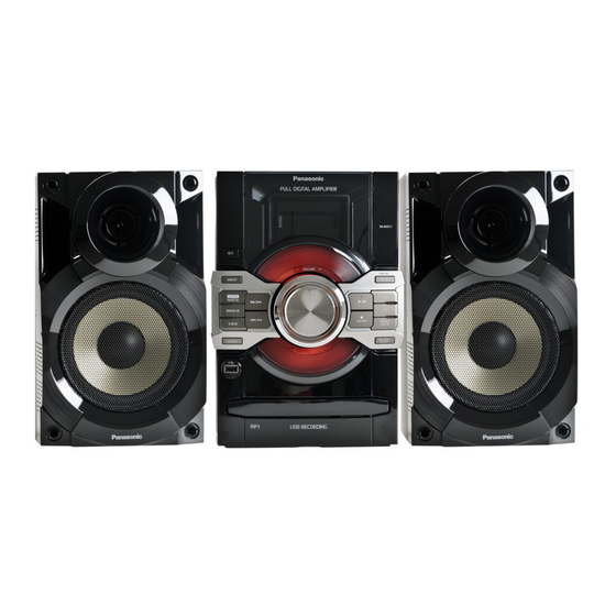
CD Stereo System
SA-AKX17PH
SA-AKX17PN
PSG1306001CE
PAGE
Advertisement
Table of Contents

Related Manuals for Panasonic SA-AKX17PH


Summary of Contents for Panasonic SA-AKX17PH
-
Page 1: Table Of Contents
2.3. Service caution based on Legal restrictions -------- 9 7.1. Speaker and A/C Connection ------------------------- 17 2.4. Handling Precautions for Traverse Unit-------------10 8 Service Mode ----------------------------------------------------- 18 © Panasonic Corporation 2013. All rights reserved. Unauthorized copying and distribution is a violation of law. - Page 2 8.1. Cold-Start--------------------------------------------------- 18 8.2. Doctor Mode Table--------------------------------------- 19 8.3. Reliability Test Mode (CD Mechanism Unit) ------- 22 8.4. Self-Diagnostic Mode ----------------------------------- 23 8.5. Self-Diagnostic Error Code Table -------------------- 23 8.6. Sales Demonstration Lock Function ---------------- 24 9 Troubleshooting Guide---------------------------------------- 25 10 Disassembly and Assembly Instructions --------------- 26 10.1.
-
Page 3: Safety Precautions
1 Safety Precautions 1.1. General Guidelines 1. IMPORTANT SAFETY NOTICE There are special components used in this equipment which are important for safety. These parts are marked by in the Schematic Diagrams, Circuit Board Layout, Exploded Views and Replacement Parts List. It is essential that these critical parts should be replaced with manufacturer’s specified parts to prevent X-RADIATION, shock, fire, or other hazards. -
Page 4: Before Use (For Ph Only)
1.2. Before Use (For PH only) Be sure to disconnect the mains cord before adjusting the voltage selector as shown in Figure 1-2. Use a minus(-) screwdriver to set the voltage selector (on the rear panel) to the voltage setting for the area in which the unit will be used. -
Page 5: Power Supply Using Smps
1.5. Power Supply using SMPS This model uses Switching Mode Power Supply (SMPS) to provide the power supply to the unit. Here is the supplied part no. for the SMPS Module for the models 1) N0AB3GK00008 (For PN) 2) N0AD3GK00001 (For PH) 1.5.1. -
Page 6: Safety Parts Information
1.6. Safety Parts Information Safety Parts List: There are special components used in this equipment which are important for safety. These parts are marked by in the Schematic Diagrams, Exploded View & Replacement Parts List. It is essential that these critical parts should be replaced with manufacturer’s specified parts to prevent shock, fire or other hazards. -
Page 7: Warning
2 Warning 2.1. Prevention of Electrostatic Discharge (ESD) to Electrostatically Sensi- tive (ES) Devices Some semiconductor (solid state) devices can be damaged easily by static electricity. Such components commonly are called Elec- trostatically Sensitive (ES) Devices. The following techniques should be used to help reduce the incidence of component damage caused by electrostatic discharge (ESD). -
Page 8: Precaution Of Laser Diode
2.2. Precaution of Laser Diode Caution: This product utilizes a laser diode with the unit turned “on”, invisible laser radiation is emitted from the pickup lens. Wavelength: 790 nm (CD) Maximum output radiation power from pickup: 100 W/VDE Laser radiation from the pickup unit is safety level, but be sure the followings: 1. -
Page 9: Service Caution Based On Legal Restrictions
2.3. Service caution based on Legal restrictions 2.3.1. General description about Lead Free Solder (PbF) The lead free solder has been used in the mounting process of all electrical components on the printed circuit boards used for this equipment in considering the globally environmental conservation. The normal solder is the alloy of tin (Sn) and lead (Pb). -
Page 10: Handling Precautions For Traverse Unit
2.4. Handling Precautions for Traverse Unit The laser diode in the optical pickup unit may break down due to static electricity of clothes or human body. Special care must be taken avoid caution to electrostatic breakdown when servicing and handling the laser diode in the traverse unit. Cautions to Be Taken in Handling the Optical Pickup Unit 2.4.1. -
Page 11: Grounding For Electrostatic Breakdown Prevention
2.5. Grounding for electrostatic breakdown prevention • As for parts that use optical pick-up (laser diode), the optical pick-up is destroyed by the static electricity of the working environ- ment. Repair in the working environment that is grounded. 2.5.1. Worktable grounding •... -
Page 12: Service Navigation
3 Service Navigation 3.1. Service Information This service manual contains technical information which will allow service personnel’s to understand and service this model. Please place orders using the parts list and not the drawing reference numbers. If the circuit is changed or modified, this information will be followed by supplement service manual to be filed with original service manual. -
Page 13: Specifications
(200 kHz step) (for PN) Front Speakers: SB-AKX16PN-K 75 (unbalanced) Antenna terminals System: SC-AKX17PH-K Amplitude modulation (AM) Main Unit: SA-AKX17PH-K Frequency range 522 kHz to 1629 kHz Front Speakers: SB-AKX16PN-K (9 kHz step) (for PH) 520 kHz to 1630 kHz... -
Page 14: General/Introduction
5 General/Introduction 5.1. Media Information... -
Page 15: Location Of Controls And Components
6 Location of Controls and Components 6.1. Remote Control Key Button Operation... -
Page 16: Main Unit Key Button Operation
6.2. Main Unit Key Button Operation... -
Page 17: Installation Instructions
7 Installation Instructions 7.1. Speaker and A/C Connection... -
Page 18: Service Mode
8 Service Mode 8.1. Cold-Start Here is the procedure to carry out cold-start or initialize to shipping mode. 1. Unplug AC power cord 2. Press & hold [POWER] button 3. Plug AC power cord while [POWER] button being pressed FL Display will show “_ _ _ _ _ _ _ _” 4. -
Page 19: Doctor Mode Table
8.2. Doctor Mode Table 8.2.1. Doctor Mode Table 1 Item Key Operation FL Display Mode Name Description Front Key Doctor Mode 1. Press [ ] button on main unit follow by [4] and [7] on remote control. 2. To exit, press [DELETE] button on remote control or, press [POWER, /I] button on Main Unit... - Page 20 8.2.2. Doctor Mode Table 2 Item Key Operation FL Display Mode Name Description Front Key Volume Setting To check the volume setting of the In Doctor Mode: Check main unit. 1. Press [7], [8], [9] button on the remote control. Press [7]: VOL50 Volume Press [8]: VOL35...
- Page 21 8.2.3. Doctor Mode Table 3 Item Key Operation FL Display Mode Name Description Front Key To display result of In Doctor Mode : 1. Press [10] [4] button Self- Adjustment self-adjustment for CD. Test on the remote control. Display of auto adjustment result Reference table: ERROR Code...
-
Page 22: Reliability Test Mode (Cd Mechanism Unit)
8.3. Reliability Test Mode (CD Mechanism Unit) Below is the process flow chart of the aging test for the CD Mechanism Unit. Figure 8-1 Reliability Test (Loading) Figure 8-2 Reliability Test (Traverse) Figure 8-3 Reliability Test (Combination) -
Page 23: Self-Diagnostic Mode
8.4. Self-Diagnostic Mode Item Key Operation FL Display Mode Name Description Front Key Self Diagnostic To enter into self diagnostic checking Step 1: Select CD mode Mode (Ensure no disc is inserted). Step 2: Press & hold [ ] button follow by [ ] on main unit for 2 seconds. -
Page 24: Sales Demonstration Lock Function
8.6. Sales Demonstration Lock Function 8.6.1. Entering into Sales demonstration lock mode Here is the procedures to enter into the Sales demonstration lock mode. Step 1: Turn on the unit. Step 2: Select to any mode function. Step 3: Press and hold [ ] and [CD] keys for 5 sec or more. -
Page 25: Troubleshooting Guide
9 Troubleshooting Guide “Contents for this section is not available at time of issue”... -
Page 26: Disassembly And Assembly Instructions
10 Disassembly and Assembly Instructions • Illustration is based on SA-AKX17PH-K. Caution Note: • This section describes the disassembly and/or assembly procedures for all major printed circuit boards & main compo- nents for the unit. (You may refer to the section of “Main components and P.C.B Locations” as described in the service manual) •... -
Page 27: Disassembly Flow Chart
10.2. Disassembly Flow Chart... -
Page 28: Main Components And P.c.b. Locations
10.3. Main Components and P.C.B. Locations... -
Page 29: Disassembly Of Top Cabinet
10.4. Disassembly of Top Cabinet Step 4 Slightly lift up to remove the Top Cabinet. Step 1 Remove 2 screws on each side. Step 2 Remove 5 screws. Step 3 Release both sides of Top Cabinet outwards as arrow shown. Caution: During assembling, ensure that the Top Cabinet is inserted properly into the Front Panel Unit as shown. -
Page 30: Disassembly Of Front Panel Unit
10.5. Disassembly of Front Panel Step 4 Release tabs at bottom of unit. Unit • Refer to “Disassembly of Top Cabinet”. Step 1 Detach 5P Cable Wire at the connector (CN2002) on Main P.C.B. Step 2 Detach 17P FFC at the connector (CN2000) on Main P.C.B. -
Page 31: Disassembly Of Panel P.c.b. And Lcd P.c.b
10.6. Disassembly of Panel P.C.B. Step 3 Release catches in sequences (1-6). and LCD P.C.B. • Refer to “Disassembly of Top Cabinet”. • Refer to “Disassembly of Front Panel Unit”. Step 1 Remove Volume Knob. Step 4 Slightly lift up Panel P.C.B. Step 2 Remove 6 screws. -
Page 32: Disassembly Of Remote Sensor P.c.b
10.8. Disassembly of USB P.C.B. Step 5 Remove 2 screws. Step 6 Remove the Panel P.C.B. and LCD P.C.B.. • Refer to “Disassembly of Top Cabinet”. • Refer to “Disassembly of Front Panel Unit”. • Refer to “Disassembly of Panel P.C.B. and LCD P.C.B. Step 1 Remove 1 screw. -
Page 33: Disassembly Of Rear Panel
Step 2 Remove CD Lid. Step 2 Detach Voltage Selector P.C.B.. 10.10. Disassembly of Rear Panel. • Refer to “Disassembly of Top Cabinet”. Step 3 Lift up Inner Chassis Unit to release the catches Step 1 Remove 9 screws. between the Inner Chassis Unit and the Rear Panel. -
Page 34: Disassembly Of Main P.c.b
10.12. Disassembly of SMPS Module Step 4 Release 2 tabs. Step 5 Release Rear Panel. and Voltage Selector P.C.B. • Refer to “Disassembly of Top Cabinet”. • Refer to “Disassembly of Rear Panel”. Step 1 Detach 13P Cable Wire at the connector (CON2) on SMPS Module. -
Page 35: Disassembly Of Cd Mechanism Unit
10.13. Disassembly of CD Mecha- Step 6 Remove 1 screw. nism Unit • Refer to “Disassembly of Top Cabinet”. • Refer to “Disassembly of Front Panel Unit”. Step 1 Remove 8 screws. Step 7 Release 2 catches. Step 8 Lift up and remove the Inner Chassis Unit.. Step 2 Detach Voltage Selector P.C.B. -
Page 36: Disassembly Of Cd Interface P.c.b
10.14. Disassembly of CD Interface Caution: During assembling, ensure that Inner Chassis Unit is catched onto Rear Panel properly. P.C.B. • Refer to “Disassembly of Top Cabinet”. • Refer to “Disassembly of Front Panel Unit”. • Refer to “Disassembly of CD Mechanism Unit”. Step 1 Remove 2 screws. -
Page 37: Service Position
11 Service Position Note: For description of the disassembly procedures, see Step 5 Lift up the Main P.C.B. as arrow shown. the Section 10. 11.1. Checking of Panel P.C.B. and LCD P.C.B. Step 1 Remove Top Cabinet. Step 2 Remove Front Panel Unit. Step 3 Remove the Panel P.C.B. -
Page 38: Checking And Repairing Of Main P.c.b. (Side A)
11.3. Checking and Repairing of Main P.C.B. (Side A) Step 1 Remove Top Cabinet. Step 2 Remove Front Panel Unit. Step 3 Remove Rear Panel. Step 4 Remove Main P.C.B.. Step 5 Remove SMPS Module and Voltage Selector P.C.B.. Step 6 Positioned the Main P.C.B., SMPS Module and the Volt- age Selector P.C.B. -
Page 39: Simplified Block Diagram
12 Simplified Block Diagram... -
Page 40: Block Diagram
OPEN SW OPEN SW OPEN SW CD OPEN SW CN7001 CN7002 CN8251 CLOSE SW CLOSE SW CLOSE SW CD CLOSE SW CD INTERFACE P.C.B. NOTE: “ * ” REF IS FOR INDICATION ONLY SA-AKX17PH/PN SERVO & SYSTEM CONTROL (1/2) BLOCK DIAGRAM... - Page 41 VOL JOGB VOL JOGB VOLUME VOL JOGB 81 PANEL P.C.B. DC DET AMP FAN DC DET1 40 DC DET AMP FAN FROM AUDIO NOTE: “ * ” REF IS FOR INDICATION ONLY SA-AKX17PH/PN SERVO & SYSTEM CONTROL (2/2) BLOCK DIAGRAM...
-
Page 42: Audio
TO SERVO & SYSTEM CONTROL DAP I2S BCKO 31 LRCLKO DAP I2S LRCKO DAP I2S LRCKO 30 SCLKO TU INT TU INT TU RST TU RST FROM/TO SERVO & SYSTEM CONTROL TU SCL TU SCL TU SDA TU SDA SA-AKX17PH/PN AUDIO BLOCK DIAGRAM... -
Page 43: Power Supply
CN1000* AM-BP AM-BP FROM/TO AM BP SERVO & SYSTEM CONTROL CN1000* SYNC SYNC SYNC CN1000* SMPS-ID SMPS-ID SMPS ID CN1000* TEMP DET TEMP DET TEMP DET NOTE: “ * ” REF IS FOR INDICATION ONLY SA-AKX17PH/PN POWER SUPPLY BLOCK DIAGRAM... -
Page 44: Wiring Connection Diagram
CD INTERFACE P.C.B. (SOLDER SIDE) (SOLDER SIDE) IR9000 JK9300 CN7002 USB PORT SENSOR M7301* REMOTE SENSOR P.C.B. (TRAVERSE CN7001 MOTOR) (SOLDER SIDE) TO LOADING P.C.B. (CD MECHANISM UNIT BRS11C) NOTE: " * " REF IS FOR INDICATION ONLY. SA-AKX17PH/PN WIRING CONNECTION DIAGRAM... -
Page 45: Schematic Diagram
15 Schematic Diagram 15.1. Schematic Diagram Notes • This schematic diagram may be modified at any time with the development of new technology. Notes: S7201: Reset switch S9000: USB switch. S9001: Power switch ( S9002: CD switch. S9003: Latin Preset EQ switch. S9004: Radio/EXT-IN switch. -
Page 47: Main (Cd Servo) Circuit
BUS_DAT2_SD VREF BUS_DAT1_SD R8506 VREF (CD MECHANISM VCC(5V) BUS_DAT0_SD R8507 VCC(5V) UNIT BRS11C) BUS_DAT3_SD R8504 CD-LD MD/LPD LB8501 LB8205 J0JHC0000045 J0JHC0000045 DVD-LD C8501 GND-LD FP9003 NRST NRST STBY3.3V FOR DEBUG STBY3.3V SDATA SDATA SCLK SCLK SA-AKX17PH/PN MAIN (CD SERVO) CIRCUIT... - Page 48 X8101 100K STBY3.3V C8015 C8016 DGND SDATA SCLK NRST DGND PW_5V PW_6V DGND PW_5V MI: MAIN (MICON) SCHEMATIC DIAGRAM - 4 DD: MAIN (DAP_DSP) SCHEMATIC DIAGRAM - 6 SA-AKX17PH/PN MAIN (CD SERVO) CIRCUIT TU: MAIN (TUNER_AUX) SCHEMATIC DIAGRAM - 7...
- Page 49 R9004 DGND DGND C8101 1000p BUS_D+ BUS_D- R8027 DGND DGND PW_3R3V_DAC C8061 PW_3R3V_DIG C8064 C8102 DGND DGND PW_5V PW_6V DGND PW_5V MI: MAIN (MICON) SCHEMATIC DIAGRAM - 4 SA-AKX17PH/PN MAIN (CD SERVO) CIRCUIT TU: MAIN (TUNER_AUX) SCHEMATIC DIAGRAM - 7...
-
Page 50: Main (Micon) Circuit
DA: MAIN (DAMP) SCHEMATIC DIAGRAM - 5 DD: MAIN (DAP_DSP) SCHEMATIC DIAGRAM - 6 TU: MAIN (TUNER_AUX) SCHEMATIC DIAGRAM - 7 VO: MAIN (VOLTAGE REGULATOR) SCHEMATIC DIAGRAM - 8 SA-AKX17PH/PN MAIN (MICON) CIRCUIT NOTE: “ * ” REF IS FOR INDICATION ONLY... -
Page 51: Main (Damp) Circuit
Q6300 SPEAKER PROTECTION Q6001 B1ABCF000011 B1ABCF000011 R6054 SPEAKER PROTECTION R6070 C6068 DC DETECT MI: MAIN (MICON) SCHEMATIC DIAGRAM - 4 DD: MAIN (DAP_DSP) SCHEMATIC DIAGRAM - 6 NOTE: “ * ” REF IS FOR INDICATION ONLY SA-AKX17PH/PN MAIN (DAMP) CIRCUIT... -
Page 52: Main (Dap_Dsp) Circuit
C6508 R6531 DAP_I2S_OUT VR_DIG SDOUT C6530 C6509 CD: MAIN (CD SERVO) SCHEMATIC DIAGRAM - 1~3 MI: MAIN (MICON) SCHEMATIC DIAGRAM - 4 DA: MAIN (DAMP) SCHEMATIC DIAGRAM - 5 TU: MAIN (TUNER_AUX) SCHEMATIC DIAGRAM - 7 SA-AKX17PH/PN MAIN (DAP_DSP) CIRCUIT... -
Page 53: Main (Tuner_Aux) Circuit
AM ANT AM ANT AM ANT DGND 0.47 4.7K 4.7K TU_SDA TU_SCL G2A380Y00002 TU_RST CD: MAIN (CD SERVO) SCHEMATIC DIAGRAM - 1~3 MI: MAIN (MICON) SCHEMATIC DIAGRAM - 4 DD: MAIN (DAP_DSP) SCHEMATIC DIAGRAM - 6 SA-AKX17PH/PN MAIN (TUNER_AUX) CIRCUIT... -
Page 54: Main (Voltage Regulator) Circuit
R1008 VSENSE SS/TR C1019 R1045 C1020 R1006 0.01 PWRGD RT/CLK R1016 CD: MAIN (CD SERVO) SCHEMATIC DIAGRAM - 1~3 MI: MAIN (MICON) SCHEMATIC DIAGRAM - 4 SA-AKX17PH/PN MAIN (VOLTAGE REGULATOR) CIRCUIT NOTE: “ * ” REF IS FOR INDICATION ONLY... -
Page 55: Panel, Lcd, Usb, Remote Sensor & Cd Interface Circuit
[44] SEG0 DGND SEG13 SEG12 SEG12 CKA2 CKA1 SEG11 SEG11 R903 37 38 40 42 42 M7301* R908 TRAVERSE MOTOR NOTE: “ * ” REF IS FOR INDICATION ONLY SA-AKX17PH/PN PANEL / LCD / USB REMOTE SENSOR / CD INTERFACE CIRCUIT... -
Page 56: Printed Circuit Board
R2316 R2064 R2066 C8042 C8041 LB8201 C2054 C8043 C8048 C8033 C8046 C8011 LB51 R2337 C8075 C8101 TP2000 C8067 C8068 IC2007 C8069 R2144 R2145 TP2002 TP69 C2061 C8025 C8026 TP67 C2077 TP2001 LB8202 C8204 3610B 3610B (SIDE A) SA-AKX17PH/PN MAIN P.C.B. - Page 57 CN2002 (FOR DEBUG) AM ANT IC8251 C2017 C8515 TP64 CN8251 C8256 C8261 R8263 R8262 IC2030 FP8201 (TO OPTICAL PICKUP UNIT (CD MECHANISM UNIT BRS11C)) 3610B 3610B (SIDE B) NOTE: " * " REF IS FOR INDICATION ONLY. SA-AKX17PH/PN MAIN P.C.B.
-
Page 58: Panel, Lcd, Usb & Remote Sensor P.c.b
R9300 JK9300 D9300 ZJ9001* S9001 USB PORT (POWER) VOLUME CN9001 REMOTE SENSOR P.C.B. (REP4903BD) 3611AD-1 3611AD-1 3611AA-1 3611AA-1 CN9002 IR9000 SENSOR NOTE: " * " REF IS FOR INDICATION ONLY SA-AKX17PH/PN PANEL / LCD / USB / REMOTE SENSOR P.C.B. -
Page 59: Cd Interface P.c.b
16.3. CD Interface P.C.B. CD INTERFACE P.C.B. (REP4945A) M7302* (SPINDLE MOTOR) S7201 (RESET) CN7002 CN7001 M7301* TO LOADING P.C.B. (TRAVERSE (CD MECHANISM MOTOR) UNIT BRS11C) 3556A 3556A NOTE: " * " REF IS FOR INDICATION ONLY SA-AKX17PH/PN CD INTERFACE P.C.B. -
Page 61: Appendix Information Of Schematic Diagram
CD PLAY STANDBY IC2006 REF NO. MODE CD PLAY STANDBY IC2006 REF NO. MODE CD PLAY STANDBY REF NO. IC2006 MODE CD PLAY STANDBY REF NO. IC2006 MODE CD PLAY STANDBY IC2007 REF NO. MODE CD PLAY STANDBY SA-AKX17PH/PN MAIN P.C.B. - Page 62 CD PLAY STANDBY IC6500 REF NO. MODE CD PLAY STANDBY IC6500 REF NO. MODE CD PLAY STANDBY IC7704 REF NO. MODE CD PLAY STANDBY IC7704 REF NO. MODE CD PLAY STANDBY IC7704 REF NO. MODE CD PLAY STANDBY SA-AKX17PH/PN MAIN P.C.B.
- Page 63 CD PLAY STANDBY IC8001 REF NO. MODE CD PLAY STANDBY IC8001 REF NO. MODE CD PLAY STANDBY IC8001 REF NO. MODE CD PLAY STANDBY IC8251 REF NO. MODE CD PLAY STANDBY IC8251 REF NO. MODE CD PLAY STANDBY SA-AKX17PH/PN MAIN P.C.B.
- Page 64 12.2 13.6 16.2 15.8 16.2 Q6300 Q8201 QR2500 REF NO. MODE CD PLAY 16.2 15.8 16.2 STANDBY 16.0 16.0 16.0 SA-AKX17PH/PN MAIN P.C.B. 17.1.5. LCD P.C.B. IC900 REF NO. MODE CD PLAY STANDBY IC900 REF NO. MODE CD PLAY STANDBY REF NO.
- Page 65 17.1.6. Waveform Table 4Vp-p(50nsec/div) 3.2Vp-p(50nsec/div) 1.8Vp-p(10usec/div) 2.8Vp-p(10usec/div) 3.2Vp-p(1usec/div) 32Vp-p(1usec/div) 3.4Vp-p(500nsec/div) 3.2Vp-p(10usec/div) 0.5Vp-p(2usec/div) 2.5Vp-p(200usec/div) 3.2Vp-p(1usec/div) 3.4Vp-p(100nsec/div) 0.4Vp-p(5usec/div)
-
Page 67: Exploded View And Replacement Parts List
18.1.1. Cabinet Parts Location DP900 (PANEL P.C.B.) CN9001 *ZJ9001 IR9000 (LCD P.C.B.) CN9002 *ZJ6000 (REMOTE SENSOR P.C.B.) CN9000 VR9000 (USB P.C.B.) JK9300 *ZJ9300 SA-AKX17PH/PN-K NOTE: “ * ” PART IS NOT SUPPLIED / REF IS FOR INDICATION ONLY. CABINET DRAWINGS... - Page 68 FP8201 CN8251 CN2002 (MAIN P.C.B.) CN2001 CN2000 (FOR PH ONLY) *CN1000 (SMPS MODULE P.C.B.) CD MECHANISM (BRS11C) (CD INTERFACE P.C.B.) CN7002 S7201 CN7001 SA-AKX17PH/PN-K NOTE: “ * ” PART IS NOT SUPPLIED / REF IS FOR INDICATION ONLY. CABINET DRAWINGS...
- Page 69 18.1.2. Packaging ACCESSORIES BAG SA-AKX17PH/PN AC CORD (FOR PH ONLY) AC CORD (FOR PN ONLY) A1-1 O/I BOOK FM INDOOR ANTENNA SB-AKX16PN AC PLUG ADAPTER (FOR PH ONLY) AM LOOP ANTENNA F R O N T POLYFOAM (TOP) POLYFOAM (BOTTOM)
- Page 71 18.1.3. Mechanical Replacement Part List Safety Ref. No. Part No. Part Name & Remarks Description Safety Ref. No. Part No. Part Name & Remarks RMKX1031A-1 BOTTOM CHAS- Description RMNX0298 PCB SPACER CABINET RMQ2134 MECHA HOLDER CHASSIS RSC1228 THERMAL PAD RMNX1011-W2 HOLDER REE1730 10P FFC (MAIN-...
- Page 72 Safety Ref. No. Part No. Part Name & Remarks Description RAE1036Z-V TRAVERSE ASS'Y XTN2+6GFJ SCREW PACKING MATE- RIALS RPG0F84 PACKING CASE RPG0F85 PACKING CASE RPN2483-1 POLYFOAM RPFX0198-1 MIRAMAT ACCESSORIES N2QAYB000911 REMOTE CON- TROL A1-1 RKK-PM500EBK BATTERY COVER K2CB2CB00022 AC CORD K2CQ2YY00119 AC CORD RQT9843-1M...
-
Page 73: Electrical Replacement Parts List
18.2. Electrical Replacement Parts List Safety Ref. No. Part No. Part Name & Remarks Description Safety Ref. No. Part No. Part Name & Remarks IC8401 C3FBMY000309 (E.S.D) Description TRANSISTORS PRINTED CIR- CUIT BOARDS Q900 B1GBCFJN0033 TRANSISTOR (E.S.D) Q2001 B1GBCFLL0037 TRANSISTOR (E.S.D) PCB1 REP4902M... - Page 74 Safety Ref. No. Part No. Part Name & Remarks Safety Ref. No. Part No. Part Name & Remarks Description Description S7201 K0L1BA000158 SW RESET JK6000 K4AC04B00030 JK SPEAKERS S9000 EVQ21405RJ SW USB JK6002 K2HA2YYA0009 JK AUX IN S9001 EVQ21405RJ SW POWER S9002 EVQ21405RJ SW CD...
- Page 75 Safety Ref. No. Part No. Part Name & Remarks Safety Ref. No. Part No. Part Name & Remarks Description Description D0GB222JA065 2.2K 1/10W R2319 D0GB101JA065 1/10W R901 D0GB153JA065 1/10W R2323 D0GB101JA065 1/10W R903 D0GB471JA065 1/10W R2324 D0GB101JA065 1/10W R905 D0GBR00J0004 1/10W R2325 D0GB101JA065...
- Page 76 Safety Ref. No. Part No. Part Name & Remarks Safety Ref. No. Part No. Part Name & Remarks Description Description R6536 D0GB101JA065 1/10W R9005 D0GB122JA065 1.2K 1/10W R6542 D0GB103JA065 1/10W R9006 D0GB152JA065 1.5K 1/10W R6543 D0GB472JA065 4.7K 1/10W R9007 D0GB152JA065 1.5K 1/10W R6544...
- Page 77 Safety Ref. No. Part No. Part Name & Remarks Safety Ref. No. Part No. Part Name & Remarks Description Description C6036 F1H1H104B047 0.1uF 50V C8026 F1H0J4750005 4.7uF 6.3V C6039 F1K1H105A138 C8027 F1H1H102B047 1000pF 50V C6040 F2A1H4710072 470uF 50V C8028 F1H1H104B047 0.1uF 50V C6042 ECQV1H474JL3...