Advertisement
Quick Links
IMPORTANT: READ THE FOLLOWING INFORMATION BEFORE OPERATING THIS PRODUCT!
R V P R O D U C T S G R O U P
INSTALLATION, OPERATING AND MAINTENANCE INSTRUCTIONS
TOOLS NEEDED:
9/16" Socket or Ratchet Wrench
9/16" Open End Wrench
3/8" or 1/2" Power Drill
1/4" and 3/8" Drill Bit
DETERMINING CORRECT MOUNTING LOCATION
This product will mount on trailer frames 52" to 72" wide (side to side). The closer the carrier can be mounted to
the frame, the less chance of ground clearance issues. There will need to be unobstructed space side to side on the
bottom of trailer frame for the carrier to install correctly
STEP 1: Park and level your travel trailer or fifth-wheel trailer. Prevent wheels from rolling by using tire chocks.
STEP 2: Install the Support Wings before mounting to the frame. Using the 3/8" x 7/8" L bolts and 3/8" Nylon nuts,
mount each Support Wing to the two sets of predrilled holes on the Main Carrier Assy. Securely tighten each bolt to
20 lb ft torque.
STEP 3: Determine a location on the trailer frame to mount the carrier considering warnings and location suggestions
above. The location should allow easy access to drive nut.
STEP 4: After identifying the desired location on the frame; use the frame bracket (on either side of the carrier) as
a template by marking the center of the two holes with a marker that can be easily seen. Once marked, drill a pilot
hole using a 1/4" drill bit and then a 3/8" drill bit to finish enlarging each hole. Using two 3/8" x 1 1/4" L bolts and 3/8"
Nylon nuts, loosely tighten to secure one side of the carrier in place.
STEP 5: Repeat Step 3 on the opposite side of the frame. Be sure that the location on the opposite side is exactly
parallel to the location in Step 3. Slide the Main Carrier Assy together with the Telescopic Channel to help determine
this location.
STEP 6: Once each side is loosely attached to the frame, you will need to drill a 1/4" pilot hole thru the predrilled
center hole in the Telescopic Channel. This hole is located on the Telescopic Channel however you will be drilling into
the Main Carrier Assy. This is a pass thru hole so you will need to drill the 1/4" pilot hole on each side. Using a 3/8"
drill bit, enlarge the hole on each side of the carrier. Using the 3/8" x 2 1/2" L bolt and 3/8" Nylon nut, tighten to 23 lb
ft torque to secure the Main Carrier Assy to the Telescopic Channel.
STEP 7: Securely tighten the four bolts holding the carrier to the frame (two on each side of frame) to 20 lb ft torque.
WARNING: BEFORE DRILLING HOLES INTO THE FRAME, BE SURE THERE ARE NO ITEMS THE DRILL BIT WILL DAMAGE (i.e.: electrical
or LP lines, braking or towing related items, holding or water tanks, etc.). IT MAY BE NECESSARY TO LOWER UNDERBELLY SHEET TO
ACCESS FRAME FOR INSPECTION AND INSTALLATION. ALSO CHECK WITH THE RV MANUFACTURER OR SELLING DEALER TO MAKE SURE
NO WARRANTIES ARE AFFECTED BY DRILLING INTO THE TRAILER FRAME. BAL WARRANTIES ARE LIMITED TO PRODUCTS ONLY USED FOR
THEIR DESIGNED AND INTENEDED USE. ANY ABUSE OR MISUSE IS THE LIABLITY OF THE OWNER AND/OR INSTALLER.
®
INSTALLATION INSTRUCTIONS
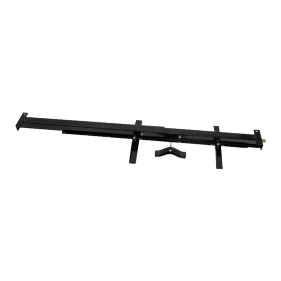
RETRACT-A-SPARE TIRE CARRIER
FOR USE ON ALL RECREATIONAL VEHICLES
28240
Advertisement

Summary of Contents for BAL R.V. Products 28240
-
Page 1: Tools Needed
IMPORTANT: READ THE FOLLOWING INFORMATION BEFORE OPERATING THIS PRODUCT! 28240 ® RETRACT-A-SPARE TIRE CARRIER FOR USE ON ALL RECREATIONAL VEHICLES R V P R O D U C T S G R O U P INSTALLATION, OPERATING AND MAINTENANCE INSTRUCTIONS TOOLS NEEDED: 9/16”... - Page 2 OPERATION Once the carrier is mounted securely, use a 3/4” ratchet, socket wrench, box end, or jack speed handle to lower the cable attached to the tire mount to the ground. Slide the tire under the carrier and insert the tire mount into the center hole of the wheel.