Table of Contents
Advertisement
Available languages
Available languages
Advertisement
Chapters
Table of Contents

Related Manuals for GE 29884


Summary of Contents for GE 29884
- Page 1 Outdoor Antenna User’s Manual...
- Page 2 WARNING: INSTALLATION OF THIS PRODUCT NEAR POWER LINES IS DANGEROUS, FOR YOUR SAFETY, FOLLOW THE INSTALLATION DIRECTIONS. WATCH FOR WIRES! YOU CAN BE KILLED IF THIS ANTENNA COMES NEAR ELECTRIC POWER LINES. READ INSTRUCTIONS!
-
Page 3: Table Of Contents
TABLE OF CONTENTS IMPORTANT SAFETY INSTRUCTIONS ............4 SELECT AND MEASURE YOUR INSTALLATION SITE ......5 CHOOSE A MOUNT TYPE ................6 ASSEMBLY INSTRUCTIONS - Parts List ..........7 ASSEMBLY INSTRUCTIONS - Assembling the Antenna ....9 ASSEMBLY INSTRUCTIONS - Ground the Antenna Mount ..13 EASY INSTALLATION GUIDES .............. -
Page 4: Important Safety Instructions
IMPORTANT SAFETY INSTRUCTIONS: • NEVER touch ANYTHING or ANYONE in contact with a power line. You can be electrocuted. In case of an accident or emergency, call 911 immediately for help. • Inspect your installation site carefully for power lines. Make sure there is no possibility the antenna, its mounting structure or your ladder can come into contact with power lines. -
Page 5: Select And Measure Your Installation Site
SELECT AND MEASURE YOUR INSTALLATION SITE Key things to consider in choosing the antenna installation site are: 1) Choose a SAFE location that is far away from power lines. Keep the distance between power lines and the antenna and its mounting structure at least 2 times the combined height of the antenna and its mounting structure added together. -
Page 6: Choose A Mount Type
CHOOSE A MOUNT TYPE: Some examples of common mounting options are shown below. Follow the installation instructions for the mount you will use. 1) J-Mount: (Provided) 2) Ridge Mount: (Not provided) 3) Chimney Mount: (Not provided) 4) Wall Mount: (Not provided) IF YOU ARE UNSURE OR DO NOT FEEL CAPABLE OF INSTALLING THIS ANTENNA, CONTACT A PROFESSIONAL INSTALLER IN YOUR AREA. -
Page 7: Assembly Instructions - Parts List
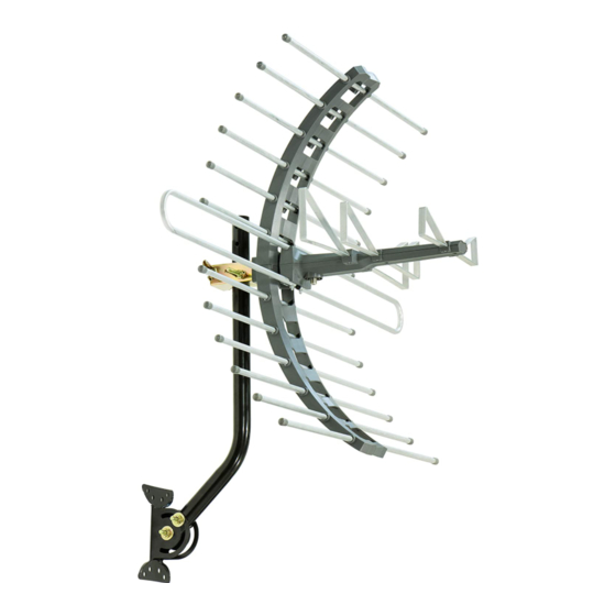
ASSEMBLY INSTRUCTIONS: Thank you for purchasing the GE 29884 Outdoor Antenna. This antenna is a sturdy, high-performing antenna designed to receive UHF and VHF broadcasted signals. The small, compact design allows you to install the antenna almost anywhere on the outside of your house. - Page 8 M6 X 10mm Bolt 2 ea. M6 X 12mm Washers 2 ea. Rubber End Caps 24 ea. “J” Mast (15/16” or 2.5 cm) 1 ea. Mounting Bracket 1 ea. ¼ X 2” Lag Screws 4 ea. M6 X 50mm Bolts 2 ea.
-
Page 9: Assembly Instructions - Assembling The Antenna
ASSEMBLING THE ANTENNA: 1) Connecting the VHF Dipole a) Remove the foam block covering the bolts and nuts from the antenna Main Boom. b) Remove the nuts and lock washers from the bolts. c) Connect together the two halves of the VHF Dipoles, one end is tapered to slide into the other half as illustrated in (Fig. - Page 10 b) Attach in the same manor the Dipoles “B” and “A” using the M3 X 8mm Sheet Metal Screws, being careful not to overtighten the screws (Fig. 2b & Fig. 2c). Fig. 2b Fig. 2c Assembling the Reflector Note: Before assembling the Reflector, you will notice that the holes on the Reflector Brackets are not perfectly round and the center of the Reflector Rods is slightly flat.
- Page 11 e) Install the Rubber End Caps after all the Reflector Rods are assembled into the Reflector Brackets. f) Connect the two assembled halves of the Reflector Brackets together by aligning the connecting tabs and sliding the halves together until the halves are evenly aligned (Fig. 3c). Fig.
- Page 12 Installing the Assembled Antenna: a) Locate a position on the house that is far away from the power lines. Refer to the Important Safety Instructions. b) Secure the Mounting Bracket to the location selected for the antenna. The 1/4 X 2” Lag Screws have been provided for some installations.
-
Page 13: Assembly Instructions - Ground The Antenna Mount
Antenna Grounding & Connecting Coax Cables The National Electric Code (NEC) requires your outdoor antenna installation to be properly grounded. This involves grounding both the antenna and the antenna mounting structure. This helps protect you and your property in the event of static build up on the antenna or lightning near your home. - Page 14 Examples of acceptable building grounding locations are: • The building or structure grounding electrode system as covered in 250.50 in the NEC • Grounded interior metal water piping system, within 5ft. from its point of entrance to the building • Grounded nonflexible metallic power service raceway •...
- Page 15 If you are using a pre-built cable that has connectors, follow these steps. i. Cut 4 slits spaced evenly apart at the narrow tip of the provided Rubber Boot approximately ¼” in length. (Fig. 6c) Fig. 6c ii. Run the coax cable through the narrow end of the Rubber Boot and attach the cable to the antenna.
- Page 16 c) Ground the 75 OHM Grounding Block: Connect a #8 aluminum or #10 grounding wire to a screw terminal provided on the 75 ohm grounding block. Connect the other end of the wire to an acceptable building ground location. Refer to Step a) above for acceptable building grounding locations.
-
Page 17: Easy Installation Guides
EASY INSTALLATION FOR ANALOG TVS WITH SET-TOP BOX 1) Connect the coax cable from the antenna to your set-top box antenna input. Then connect another coax cable (not included) to the antenna output on the set-top box. 2) Connect the other end of that cable to the antenna input on your TV. -
Page 18: Antenna Helpful Tips
FOR FURTHER ASSISTANCE, CALL 1-800-654-8483 FOR TECHNICAL SUPPORT. MADE IN CHINA GE is a trademark of General Electric Company and is under license by Jasco Products Company LLC, 10 E. Memorial Rd., Oklahoma City, OK 73114. This Jasco product comes with a limited-lifetime warranty. - Page 19 Antena para exteriores Manual del usuario...
- Page 20 ADVERTENCIA: INSTALAR ESTE PRODUCTO CERCA DE CABLES ELÉCTRICOS ES PELIGROSO. POR SU SEGURIDAD, SIGA LAS INDICACIONES DE INSTALACIÓN. ¡PRESTE ATENCIÓN A LOS CABLES ELÉCTRICOS! EL CONTACTO DE ESTA ANTENA CON ALGÚN CABLE ELÉCTRICO PUEDE CAUSARLE LA MUERTE. ¡LEA LAS INSTRUCCIONES!
- Page 21 ÍNDICE INSTRUCCIONES DE SEGURIDAD IMPORTANTES ..........4 SELECCIONE Y MIDA EL LUGAR DE LA INSTALACIÓN .........5 ELIJA UN TIPO DE MONTAJE ...................6 INSTRUCCIONES DE ENSAMBLADO: Lista de partes ........7 INSTRUCCIONES DE ENSAMBLADO: Cómo ensamblar la antena ..................9 INSTRUCCIONES DE ENSAMBLADO: Conexión a tierra del montaje de la antena ..........13 GUÍAS PARA UNA INSTALACIÓN FÁCIL ............
-
Page 22: Instrucciones De Seguridad Importantes
INSTRUCCIONES DE SEGURIDAD IMPORTANTES NUNCA toque NADA ni a NADIE que esté en contacto con un • cable eléctrico. Podría electrocutarse. En caso de accidente o emergencia, llame al 911 de inmediato para obtener ayuda. • Inspeccione el sitio de la instalación cuidadosamente para ver si hay cables eléctricos. -
Page 23: Seleccione Y Mida El Lugar De La Instalación
SELECCIONE Y MIDA EL LUGAR DE LA INSTALACIÓN Aspectos clave que debe tener en cuenta al elegir el lugar en donde instalará la antena: 1) Seleccione un lugar SEGURO que esté alejado de los cables eléctricos. La distancia entre los cables eléctricos y la antena con su estructura de montaje debe ser, por lo menos, igual a dos veces la altura combinada de la antena y la estructura de montaje sumadas. -
Page 24: Elija Un Tipo De Montaje
ELIJA UN TIPO DE MONTAJE: A continuación, se muestran algunos ejemplos de las opciones de montaje más comunes. Siga las instrucciones de instalación correspondientes al montaje que desea utilizar. 1) Montaje en "J": (incluido) 2)Montaje sobre caballete: (no incluido) 3) Montaje sobre chimenea: (no incluido) 4) Montaje sobre pared: (no incluido) -
Page 25: Instrucciones De Ensamblado: Lista De Partes
INSTRUCCIONES DE ENSAMBLADO: Gracias por adquirir la antena GE 29884 para exteriores. Esta antena es resistente y de alto rendimiento, diseñada para recibir las señales transmitidas de UHF y VHF. Su diseño pequeño y compacto permite instalar la antena en prácticamente cualquier parte en el exterior de su casa. - Page 26 Perno M6 X 10 mm 2 unidades Arandelas M6 X 12 mm 2 unidades Tapas de goma 24 unidades Mástil en “J” (15/16 in o 2,5 cm) 1 unidad Soporte de montaje 1 unidad Tornillos de compresión de ¼ X 2 in 4 unidades Pernos M6 X 50 mm 2 unidades...
-
Page 27: Cómo Ensamblar La Antena
CÓMO ENSAMBLAR LA ANTENA: Conexión del dipolo VHF a) Retire el bloque de espuma que cubre los pernos y las tuercas del soporte principal de la antena. b) Retire las tuercas y las arandelas de los pernos. c) Conecte las dos mitades de los dipolos VHF, un extremo es cónico para deslizarse dentro de la otra mitad, como se ilustra en la (Fig. - Page 28 b) Del mismo modo, conecte los dipolos “B” y “A”, utilizando los tornillos de chapa M3 X 8 mm, teniendo cuidado de no apretar demasiado los tornillos (Fig. 2b y Fig. 2c). Fig. 2b Fig. 2c Ensamblado del reflector Nota: Antes de ensamblar el reflector, notará que los orificios en los soportes del reflector no son perfectamente redondos y el centro de las varillas del reflector es levemente plano.
- Page 29 e) Instale las tapas de goma después de haber ensamblado todas las varillas del reflector en los soportes del reflector. f) Conecte las dos mitades ensambladas de los soportes del reflector entre sí alineando las pestañas de conexión y deslizando las mitades hasta que estén alineadas de forma pareja (Fig.
- Page 30 Instalación de la antena ensamblada: a) Elija un lugar de la casa alejado de los cables eléctricos. Consulte las Instrucciones de seguridad importantes. b) Sujete el soporte de montaje en el lugar seleccionado para la antena. Se suministran tornillos de compresión de 1/4 X 2 in para algunas instalaciones.
-
Page 31: Instrucciones De Ensamblado: Conexión A Tierra Del Montaje De La Antena
Conexión a tierra de la antena y conexión de los cables coaxiales El Código Nacional Eléctrico (NEC) exige que la antena exterior esté debidamente conectada a tierra, lo cual implica conectar a tierra tanto la antena como su estructura de montaje. Eso ayuda a protegerlo a usted y a proteger su propiedad en caso de que haya acumulación de estática en la antena o caiga un rayo cerca de su casa. - Page 32 Los siguientes son ejemplos de puntos de conexión a tierra aceptables de una construcción: • El sistema de electrodos con conexión a tierra de la estructura, la construcción o el edificio, tal como se detalla en la sección 250.50 del Código NEC. •...
- Page 33 Si emplea un cable preconstruido con conectores, haga lo siguiente: Corte cuatro ranuras a una distancia uniforme en el extremo estrecho de la manga de goma suministrada de aproximadamente ¼ in (6 mm) de largo (Fig. 6c). Fig. 6c Pase el cable coaxial por el extremo estrecho de la manga de goma y conecte el cable a la antena.
- Page 34 c) Conecte a tierra el bloque de conexión a tierra de 75 ohm: Conecte un cable de conexión a tierra n.º 10 o de aluminio n.º 8 a un terminal roscado que se proporciona en el bloque de conexión a tierra de 75 ohm. Conecte el otro extremo del cable a un lugar de conexión a tierra aceptable del edificio.
-
Page 35: Guías Para Una Instalación Fácil
INSTALACIÓN FÁCIL PARA TELEVISORES ANÁLOGOS CON APARATOS DECODIFICADORES 1) Conecte el cable coaxial de la antena a la entrada correspondiente a la antena del aparato decodificador. A continuación, conecte otro cable coaxial (no incluido) a la salida correspondiente a la antena del aparato decodificador. -
Page 36: Sugerencias Útiles Relacionadas Con La Antena
PARA OBTENER MÁS AYUDA, LLAME AL 1-800-654-8483 Y PÓNGASE EN CONTACTO CON EL SERVICIO TÉCNICO. HECHO EN CHINA GE es una marca registrada de la companía General Electric Company y es utilizada bajo licencia a la companía Jasco Prodcucts Company LLC, 10 E.