Table of Contents
Advertisement
Quick Links
Advertisement
Table of Contents

Related Manuals for Oberheim GM-1000

Summary of Contents for Oberheim GM-1000
- Page 1 GM-1000 24 BIT DIGITAL SIGNAL PROCESSOR OPERATING MANUAL...
- Page 2 CAUTION RISK OF ELECTRIC SHOCK DO NOT OPEN WARNING! TO REDUCE THE DANGER OF ELECTRIC SHOCK: DO NOT REMOVE COVER (OR BACK) DO NOT EXPOSE THIS APPLIANCE TO RAIN OR MOISTURE NO USER SERVICEABLE PARTS INSIDE REFER SERVICING TO QUALIFIED SERVICE PERSONNEL This simbol is intended to This simbol is intended to alert alert the user to the presence...
-
Page 3: Table Of Contents
OBERHEIM GM 1000 Digital Signal Processor CONTENTS 1. Introduction 1.1 Precautions .................... page 81 2. Description of controls and connectors 2.1 Front panel .................... page 82 2.2 Rear panel .................... page 83 3. Installation and instructions for use 3.1 Connection examples ................page 84 3.2 Some advice about correct use of the GM 1000 ........ - Page 4 OBERHEIM GM 1000 Digital Signal Processor 7. Utility Mode: 7.1 Midi Settings................... page 142 7.2 Program Table ..................page 144 7.3 Dump ..................... page 144 7.4 Midi Monitor ................... page 145 8.Tools 8.1 Tuner ..................... page 146 8.2 Analyzer ....................page 147 9.
-
Page 5: Introduction
OBERHEIM GM 1000 Digital Signal Processor 1. INTRODUCTION 1.1 PRECAUTIONS The following is a list of a number of simple precautions to be adopted when using and maintaining the instrument in order to avoid damage to its mechanical and electronic structures: •... -
Page 6: Description Of Controls And Connectors
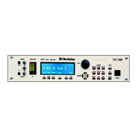
OBERHEIM GM 1000 Digital Signal Processor 2. DESCRIPTION OF CONTROLS AND CONNECTORS 2.1 FRONT PANEL Phones Output: this socket is a headphones output which allows the GM 1000 to be used even without connection to an amplification system. Phones Level: used to regulate the volume of the signal sent to the PHONES OUTPUT. -
Page 7: Rear Panel
Tap Switch: jack for connection of an optional foot-switch allowing the tap delay speed to be set. Foot Controller: connector for connection of the optional Oberheim FC 3000 foot controller. Midi In 1 and 2: five pin DIN connectors for reception of Midi messages from a remote Midi source. -
Page 8: Installation And Instructions For Use
OBERHEIM GM 1000 Digital Signal Processor 3. INSTALLATION AND INSTRUCTIONS FOR USE 3.1 CONNECTION EXAMPLES P.A. Mixer System P.A. System Send Return Volume Foot- Midi Unit Midi Controller pedal switches Midi Out Midi In A/C current Keyboard P.A. P.A. Mixer effects send... -
Page 9: Some Advice About Correct Use Of The Gm 1000
OBERHEIM GM 1000 Digital Signal Processor 3.2 SOME ADVICE ABOUT CORRECT USE OF THE GM 1000 Switch-on. Before making all the connections make sure that the amplification system volume is turned down to the minimum setting. Switch on the GM 1000 and then adjust the system volume again. -
Page 10: Structure Of The Gm 1000
OBERHEIM GM 1000 Digital Signal Processor which the operator looks at it. A trimmer marked CONTRAST on the left of the panel is provided for this purpose. 3.3 STRUCTURE OF THE GM 1000 Memory configuration. The memory of the GM 1000 is divided into four banks: A, B, C and D. - Page 11 OBERHEIM GM 1000 Digital Signal Processor Noise Gate CMP GROUP DST GROUP EQ GROUP AMP GROUP MOD GROUP SP1 GROUP SP2 GROUP DLY GROUP REV GROUP Compressor Distortion 10 Bands Gra Guitar Amp Chorus Wha - Wha Shifting Dly Stnd Dly...
-
Page 12: Play Mode
OBERHEIM GM 1000 Digital Signal Processor 4. PLAY MODE The section which follows will describe the PLAY MODE: we will discuss the way in which the GM 1000 will be used while the patches are being played. The next section, entitled EDIT MODE, will describe the procedure for programming a patch. -
Page 13: Selecting A Memorized Patch
OBERHEIM GM 1000 Digital Signal Processor 4.2 SELECTING A MEMORIZED PATCH Changing the memory bank. To select a memory bank other than the one which is active: • Locate the cursor on the memory bank indication using the CURSOR keys. - Page 14 OBERHEIM GM 1000 Digital Signal Processor The parameter modified consists of the effect send level (EFFECT LEVEL - see section 6. EFFECTS for further information) and allows the user to set the influence of the specific group within the processing chain, with values between 0 and 100. The only exception is...
-
Page 15: Edit Mode
OBERHEIM GM 1000 Digital Signal Processor 5. EDIT MODE The section which follows will describe the EDIT MODE operating method, or in other words we will discuss the way in which the GM 1000 will be used during programming of the patches. - Page 16 OBERHEIM GM 1000 Digital Signal Processor • rectangle empty: function not available. Once the effect has been selected, if it has more than one EDIT page the word PAGE above the rectangle will indicate that the parameters which can be modified are spread over more than one page.
-
Page 17: Master Level
The difference between these two values in practical terms becomes obvious when the optional Oberheim FC 3000 foot controller is used, since the foot switches it provides allow the user to switch any one of the groups set in BYPASS status to ON. -
Page 18: Memorizing A Patch
OBERHEIM GM 1000 Digital Signal Processor 5.3 MEMORIZING A PATCH Press the ENTER/WRITE key with the key enabled (the corresponding rectangle on the display must be solid) to access the patch memorization function. The display will show the relative page, which shows: •... -
Page 19: Effects
OBERHEIM GM 1000 Digital Signal Processor 6. EFFECTS The chapter which follows describes all the effects in each group. In addition to a brief description of the characteristics of the effect itself, all the parameters relating to its programming will be discussed. All the procedures described start from the main edit video page. - Page 20 OBERHEIM GM 1000 Digital Signal Processor With the aid of the CURSOR keys and the ENCODER, the following parameters can be set: Ratio parameter. Range 1:1, 1.2:1, 1.5:1, 2:1, 3:1, 5:1, 10:1, 20:1, ∞:1 This sets how much the dynamic range of the signal will be compressed on the basis of a directly proportional ratio.
- Page 21 OBERHEIM GM 1000 Digital Signal Processor Sets the value of the level of the input signal above which the limiter comes into operation. The range goes from -6 dB (Threshold = 0) to about -40 dB (Threshold = 45). Release Time parameter. Range: 0 - 100 Sets the time for which the Limiter effect persists.
- Page 22 OBERHEIM GM 1000 Digital Signal Processor Mode parameter. Range: De-Esser, Ducker Establishes which of the two functions available is to be used. Threshold parameter. Range: 0 - 45 They set the value of the level of the input signal above which the compression comes into operation and the compression ratio.
- Page 23 OBERHEIM GM 1000 Digital Signal Processor Treble parameter. Range: 0 - 100 Regulates the high band of the crossover. FREQUENCY SELECTIVE EXPANDER/GATE This is an expander which allows the filtration of the control signal. The operating principle is the opposite of that explained in the section describing the Ducker effect.
- Page 24 OBERHEIM GM 1000 Digital Signal Processor B To M Parameter Range: 63, 80, 100, 125, 160, 200, 250, 320, 400, 500, 635, 800, 1k, 1k25, 1k6, 2k, 2k5, 3k2, 4k, 5k, 6k4, 8k, 10k, 12k8, 16k Hz M To T Parameter Range: 63, 80, 100, 125, 160, 200, 250, 320, 400, 500, 635, 800, 1k, 1k25, 1k6, 2k, 2k5, 3k2, 4k, 5k, 6k4, 8k, 10k, 12k8, 16k Hz These regulate the three sections of the crossover.
-
Page 25: Distortion (Dst)
OBERHEIM GM 1000 Digital Signal Processor Env Parameter. Range: 0 - 100 Regulates the times of response to the signal dynamics. Bass Parameter. Range: 0 - 100 Middle Parameter. Range: 0 - 100 Treble Parameter. Range: 0 - 100 B To M Parameter Range: 63, 80, 100, 125, 160, 200, 250, 320, 400, 500, 635, 800, 1k,... - Page 26 OBERHEIM GM 1000 Digital Signal Processor Level parameter. Range: 0 - 100 Regulates the level of the output signal in the context of the effects chain. OVERDRIVE "Valve" type distortion, softer than Distortion. Type parameter. Range: Standard, UK Tubes, US Tubes, Modern ovd, Hot Tubes, Flattened, Brite Tube, MOS-FET#1, MOS-FET#2, MOS-FET#3.
-
Page 27: Equalizer (Eq)
OBERHEIM GM 1000 Digital Signal Processor Controls the intensity of the effect. HiDamp parameter. Range: 4K0, 3K2, 2K5, 2K0, 1K6. Displays the cut-off frequency used by a filter which eliminates all the frequencies above the one set. Level parameter. Range: 0 - 100 Regulates the level of the output signal in the context of the effects chain. - Page 28 OBERHEIM GM 1000 Digital Signal Processor Boost/Cut Range: +14dB / -14dB This filter (of shelving type) enhances or attenuates the frequencies between the value set and the maximum frequency the machine controls. The parameters which can be modified are the working frequency and the trigger level.
- Page 29 OBERHEIM GM 1000 Digital Signal Processor Bass parameter. Range: 0 - 100 Regulates the bass tone section. Middle parameter. Range: 0 - 100 Regulates the middle tone section. Treble parameter. Range: 0 - 100 Regulates the treble tone section. Notch parameter. Range: -14dB/+14dB The Notch parameter regulates a filter which has a differentiated operating mode: its enhancement zone is centred on 1225 Hz, while for attention it focuses on 1950 Hz.
- Page 30 OBERHEIM GM 1000 Digital Signal Processor Regulates the level of the output signal in the context of the effects chain. STEREO PARAMETRIC This is a parametric equalizer, meaning an equalizer in which the user is able to modify the operating frequencies, band widths and intervention levels as he pleases. This allows perfect selection of one or more frequencies to be enhanced or attenuated.
-
Page 31: Amp Simulator (Amp)
OBERHEIM GM 1000 Digital Signal Processor Low-Mid Peak filter. Frequency Range: 100, 140, 200, 280, 400, 560, 800, 1k1, 1k6 Hz Bandwith (Q) Range: 0.5, 1, 2, 3 Enhancement/Attenuation Range: +14dB / -14dB This is a peaking filter which operates on the medium-low frequencies, capable of enhancing or attenuating the frequencies around the frequency set using the parameter F;... - Page 32 OBERHEIM GM 1000 Digital Signal Processor Box Type parameter. Range: 112, 212, 412. The Box type parameter allows the user to set the type of box with which the amplifier to be simulated is equipped. 1 (112): Simulation of a combo amplifier equipped with one 12 inch speaker...
-
Page 33: Modulation (Mod)
OBERHEIM GM 1000 Digital Signal Processor 3 (115): Simulation of a combo amplifier equipped with one 15 inch speaker with bass reflex system Influence parameter. Range: 0 - 100 Parameter which sets the incidence of the BOX TYPE parameter in the context of the amp simulator. - Page 34 OBERHEIM GM 1000 Digital Signal Processor This parameter regulates the level of the direct signal. Master parameter. Range: 0 - 100 Regulates the level of the output signal in the context of the effects chain, in this case the sum of the processed sound and the direct sound, mixed by means of the EFFECT LEVEL and DIRECT LEVEL parameters.
- Page 35 OBERHEIM GM 1000 Digital Signal Processor Level parameter. Range: 0 - 100 Regulates the level of the output signal in the context of the effects chain, in this case the sum of the processed sound and the direct sound, mixed by means of the EFFECT LEVEL and DIRECT LEVEL parameters.
- Page 36 OBERHEIM GM 1000 Digital Signal Processor STEP PHASER The Step Phaser carries out a modulation on the basis of a Sample and Hold. Rate parameter. Range: 0 - 100 Sets the modulation frequency. Step parameter. Range: 0 - 100 Establishes the relationship between the modulator and the sampling. In other words, it sets the waveform which will modulate the input signal.
- Page 37 OBERHEIM GM 1000 Digital Signal Processor Attack Time parameter. Range: 0 - 100 Sets the amount of time which will pass after the input signal has exceeded the threshold before the tremolo will start. Release Time parameter. Range: 0 - 100 In contrast with the Attack parameter, this parameter sets the time for which the effect will last.
-
Page 38: Special Effects 1 (Sp1)
OBERHEIM GM 1000 Digital Signal Processor Sets the amount of time which will pass after the input signal has exceeded the threshold before the tremolo starts. Release Time parameter. Range: 0 - 100 In contrast with the Attack parameter, this parameter sets the time for which the effect will last. - Page 39 OBERHEIM GM 1000 Digital Signal Processor Manual parameter. Range: 0 - 100 Determines the point where operation of the filter starts. The operating mode is different for automatic and pedal wah. Peak parameter. Range: 1 - 10 The parameter influences the form of the wah filter, accentuating or reducing its resonance.
- Page 40 OBERHEIM GM 1000 Digital Signal Processor These two parameters act on the levels of the two lines, thus modifying the influence of the two resonance patterns. Level parameter. Range: 0 - 100 Regulates the level of the output signal in the context of the effects chain.
- Page 41 OBERHEIM GM 1000 Digital Signal Processor Frequency parameter. Range: 0 - 100 Regulates the frequency of the carrier, in the range 500 Hz - 5 KHz. Sensitivity parameter. Range: 0 - 100 This parameter regulates the sensitivity of the modulation depth parameter to the signal dynamics.
- Page 42 OBERHEIM GM 1000 Digital Signal Processor Sets the level of the input signal above which the effect is activated. Attack Time parameter. Range: 0 - 100 Sets the amount of time which will pass after the input signal has exceeded the threshold before the tremolo starts.
-
Page 43: Special Effects 2 (Sp2)
OBERHEIM GM 1000 Digital Signal Processor Regulates the effect opening time, in a range which is diversified depending on the operating mode (SLIDER/DE-ENV). Hold parameter. Range: 0 - 100 (only present in DE-ENV mode). In DE-ENV mode, it sets the time for which any transitions around the threshold will not be considered. - Page 44 OBERHEIM GM 1000 Digital Signal Processor Mode parameter. Range: 1 - 4 This parameter sets the Shifting length. Line parameter. Range: L, R in case of Stereo; A, B in case of Arpeggiator This parameter determines which of the 2 lines is to be modified. For uniformity with the selected type, the two lines are called L and R in the case of Stereo and A and B in the case of the Arpeggiator.
- Page 45 OBERHEIM GM 1000 Digital Signal Processor This parameter sets the length of the Shifting. Line parameter. Range: 1 - 3 This parameter establishes which of the 3 lines is to be modified. Naturally, only the line highlighted will be shown and modified.
- Page 46 OBERHEIM GM 1000 Digital Signal Processor Effect parameter. Range: 0 - 100 Regulates the level of the shifting line. Master parameter. Range: 0 - 100 Regulates the level of the output signal in the context of the effects chain. The second editing page is entirely dedicated to the table where the note played is combined with the note created by the Shifted in order to obtain the desired effect.
- Page 47 OBERHEIM GM 1000 Digital Signal Processor ROTARY Simulates the typical rotary speaker effect widely used in combination with the electric order. There are two rotary sections, for the basses and trebles, each with its own speed and switching time settings.
- Page 48 OBERHEIM GM 1000 Digital Signal Processor determined by the FALL TIME (Hi Section Fall Time for the High section and Lo Section Fall Time for the Low section). DENOISER As its name suggests, this effect is used to eliminate any hums or unwanted noises.
-
Page 49: Delay (Dly)
OBERHEIM GM 1000 Digital Signal Processor 6.8 DELAY (DLY) This effect is one of the best known and is used in combination with the guitar sound. It consists of fragmented, timed repetition of the original signal. It is better known as the “echo”... - Page 50 OBERHEIM GM 1000 Digital Signal Processor Control of the HOLD pedal. The Hold pedal is active on all the Delay effects. Its function is to repeat a memorized phrase indefinitely, with the following mechanism. The first time the pedal is pressed the pattern starting point is established, while the second pressure determines where it will finish;...
- Page 51 OBERHEIM GM 1000 Digital Signal Processor Feedback Hi Damp parameter. Range: None, 20K, 19K, 18K, 17K, 16K, 14K5, 12K5, 11K5, 10K, 9K, 8K, 6K35, 5K05, 4K, 2K, 1K. Displays the cut-off frequency used by a filter which eliminates all the frequencies higher than the one set.
- Page 52 OBERHEIM GM 1000 Digital Signal Processor Allows the user to modify the delay time for each of the 4 taps. Pan parameter. Range: L = 0 - 100 - R = 100 - 0 Determines the distribution of the selected tap within the stereo front.
- Page 53 OBERHEIM GM 1000 Digital Signal Processor Identifies which of the 4 delay lines is to be modified. Time parameter. Range: 0 - 800(600 - 400 - 200)msec Regulates the delay time of the delay line being modified. The maximum value depends on the delay selected: 800 msec for the first, 600 for the second, 400 for the third and 200 for the fourth.
- Page 54 OBERHEIM GM 1000 Digital Signal Processor BPM parameter. Range: 30 - 250 BPM indicates the number of beats per minute: in our case, they are assumed always to be crotchets. The parameter is used to set the delay time on the basis of the metronome speed of the song.
- Page 55 OBERHEIM GM 1000 Digital Signal Processor METRONOMIC DELAY 2 Here again, the main prerogative is the possibility of entering the delay times in musical notation rather than in milliseconds, with a value expressed as B.P.M. or beats per minute as reference.
- Page 56 OBERHEIM GM 1000 Digital Signal Processor Regulates the level of the output signal in the context of the effects chain. Control of the HOLD pedal. The procedures described for the Tap Delay apply. Control of the TAP pedal. The procedures described for Metronomic delay 1 apply.
- Page 57 OBERHEIM GM 1000 Digital Signal Processor The Type parameter sets the type of reverb and/or the size of the room whose response is to be simulated. The differentiations are obtained by controlling a large number of internal parameters, such as delays and relative amplitude of the early reflections part, and the lengths and gains of the modules which make up the reverberation part.
- Page 58 OBERHEIM GM 1000 Digital Signal Processor Regulates the attenuation frequency of the high tones in the early reflections. Early Reflections Mix Level parameter. Range: 0 - 100 Regulates the quantity of early reflections in the effect. Reverberation Eq Lo Shelve parameters.
- Page 59 OBERHEIM GM 1000 Digital Signal Processor Pre-Delay parameter. Range: 0 - 250 ms. This parameter sets the effect delay. Density parameter. Range: 0 - 10 Controls the density of the reflections. Direct parameter. Range: 0 - 100 Regulates the level of the input signal.
- Page 60 OBERHEIM GM 1000 Digital Signal Processor Early Reflections Eq Lo Shelve parameters. Frequency Range: 50, 70, 100, 140, 200, 280, 400 Hz Boost/Cut Range: +14db/-14dB Early Reflections Eq Mid Peak parameters. Frequency Range: 100, 140, 200, 280, 400, 560, 800 1k0, 1k4, 2k0, 2k8, 4k0, 5k6, 8k0 Bandwidth (Q) Range: 0.5, 1, 2, 3...
- Page 61 OBERHEIM GM 1000 Digital Signal Processor room and the absorption capacity of its walls, the position of the sound source, and the listener's position and the direction in which he is facing. Setting these programming parameters will enable you to create surprising effects, absolutely beyond the capabilities of normal reverbs: the GM 1000 will introduce you to the world of "psycho-acoustics",...
- Page 62 OBERHEIM GM 1000 Digital Signal Processor Listener Spread parameter. Range: -90° - 90°. Step 5° They regulate the angle of spread of the listening process. Positive angles indicate an outward extension of the spread. The values range from -90° to 90° at intervals of 5°.
- Page 63 OBERHEIM GM 1000 Digital Signal Processor Chamber Wall parameter. Range: North, South, East, West, Ceiling, Floor. This parameter selects the wall (or floor or ceiling) of which the absorption is to be regulated using the ABSORPTION parameter. Chamber Absorption parameter. Range: 0 - 10 Regulates the quantity of absorption of the wall chosen using the WALL parameter.
-
Page 64: Noise Gate (Ng)
This function can be used to set the parameters relating to use of the two optional pedal units which can be connected to the optional Oberheim FC 3000 remote control unit. A number of the effects parameters can be assigned to each of these two foot controllers, and can thus be controlled in real time. -
Page 65: Oberheim Gm
OBERHEIM GM 1000 Digital Signal Processor This video page is accessed from the main editing page by pressing the utility key (FTCTRL). Foot Ctrl parameter. Range: 1, 2. Selects one of the two pedals for which the parameters assigned are to be modified. -
Page 66: Midi Settings
OBERHEIM GM 1000 Digital Signal Processor 7. UTILITY MODE This section discusses a number of utility functions available on the GM 1000. procedures for use of these functions using the CURSOR keys, the VALUE encoder and the EDIT/EXIT keys are as described in the previous points. - Page 67 Sys Ex parameter: Range, ON, OFF, ALL (ON, OFF). Enables or disables reception/transmission of exclusive system Messages which allow data exchanges or communications with the optional Oberheim FC 3000 remote control (also depending on the value set in the FILTERS ON parameter). Select ON to activate the sys ex exchange function.
-
Page 68: Program Table
Midi logic. This function is very useful when using the optional Oberheim FC 3000 remote control unit, since it makes it possible to concentrate the recall of a series of 10 memory locations chosen as the user wishes, which can all be reached immediately in PROGRAM MODE by just pressing one of the number buttons on the unit (see the foot controller user manual). -
Page 69: Midi Monitor
System exclusive etc. To visualize Midi data received: • Connect the MIDI IN1 or 2 socket of the GM-1000 to the MIDI OUT socket of the MIDI unit that is going to send the data. -
Page 70: Tools 8.1 Tuner
OBERHEIM GM 1000 Digital Signal Processor 8. TOOLS 8.1 TUNER In practice, this Tool is a digital tuner which can be used to check the tuning of an input signal. Mode parameter. Selects the tuning mode. There are 12 operating options to cover the most widely varying uses. -
Page 71: Analyzer
INPUT L&R, it is in fact possible to carry out a real time analysis of the frequency content of the input signal. One of the main applications that this function of the GM-1000 is destined to perform is without doubt the frequency response measurement in enviroments of audio amplification systems. - Page 72 OBERHEIM GM 1000 Digital Signal Processor SETTING THE PARAMETERS: By pressing ANALYZER in the TOOLS section the initial settings are shown in the display; these are: • INPUT: Selects the input or the sum of inputs from which the signal to be analyzed will be taken •...
- Page 73 OBERHEIM GM 1000 Digital Signal Processor By pressing TEMPLT (Edit) it is possible to select one of the 15 memories (Template) which hold the relative data of the spectrum analyzer: After selecting the Template with the VALUE knob, press WRITE to save the results of the...
-
Page 74: Level And Digital Technology
OBERHEIM GM 1000 Digital Signal Processor 9. TIPS AND TRICKS This section of the manual contains some Tips and Tricks to help you use GM 1000 Multi effects unit to the best of its capabilities. 9.1 Levels and digital technology The GM 1000 is a totally digital unit: this characteristic means being aware of certain particulars during the programming. -
Page 75: Programming
OBERHEIM GM 1000 Digital Signal Processor 9.2 Programming Fine control of the timbre To be able to finely control the timbre of the instrument or the disired distortion, try experimenting with the COMB FILTER effect in the SP-1 group. This, in fact, excites the harmonics and will prove to be very useful for the imitation of particular sounds or to create a patch with characteristically personalized sounds. - Page 76 OBERHEIM GM 1000 Digital Signal Processor How to copy the name of a patch It is possible to copy the name of the source patch (besides its contents obviously) in to the DESTINATION patch with the following sequence ENTER/WRITE - NAME (Utility) - VALUE knob (to select the destination) - ENTER/WRITE.
-
Page 77: Factory Settings
This page shows the result of a self-test performed by the GM 1000 on the operation of its own digital signal processors, responsible for generating the effects. • CAUTION!!: this section of the control software should only be used by the staff of authorized Oberheim service centres. - 153 -... -
Page 78: Glossary Of Terms Used
OBERHEIM GM 1000 Digital Signal Processor 11. ANNEX 11.1 THE TYPES OF CONNECTORS USED Unbalanced 6.3 mm jack connector Balanced Xlr Cannon connector Used for the following sockets: Used for the following sockets: Inputs L/Mono,R - rear Inputs L/Mono,R - rear... -
Page 79: Technical Specifications
OBERHEIM GM 1000 Digital Signal Processor 12. TECHNICAL SPECIFICATIONS AUDIO PERFORMANCE DIGITAL SIGNAL PROCESSING: 2 CHANNEL A/D 18 BIT 102 dB 128 X OVERSAMPLING SIGMA DELTA 2 CHANNEL D/A 18 BIT 102 dB 64 X OVERSAMPLING SIGMA DELTA DATA PATH... -
Page 80: Oberheim Gm
OBERHEIM GM 1000 Digital Signal Processor LINE IN REAR (CANNON): CONNECTORS (2x) BALANCED CANNON XLR INPUT IMPEDANCE 10 KOHM INPUT SENSIBILITY 10 KOHM INPUT SENSIBILITY +4 DMB NOMINAL MIDI IN: CONNECTORS DIN 5 PIN x 2 OUTPUTS PHONES: CONNECTORS JACK STEREO TRS... - Page 81 OBERHEIM GM 1000 Digital Signal Processor MIDI IMPLEMENTATION CHART Oberheim GM 1000 Date:03-Lug-96 Digital Signal Processor Version: 1.33 FUNCTION ... TRANSMITTED RECOGNIZED REMARKS BASIC DEFAULT CHANNEL 1 - 16 1 - 16 CHANGED Default MODE Mode 3 Mode 3 Messages...
- Page 83 LITHIUM BATTERY WARNING CAUTION! This product contains a lithium battery There is danger of explosion if battery is incorretly replaced. Replace only with a Maxell CR2 32. Replace only with the correct polarity. Discard used battery according to manufacturer’s instruction’s. ADVARSEL! Lithiumbatteri –...