Table of Contents
Advertisement
Available languages
Available languages
User Manual
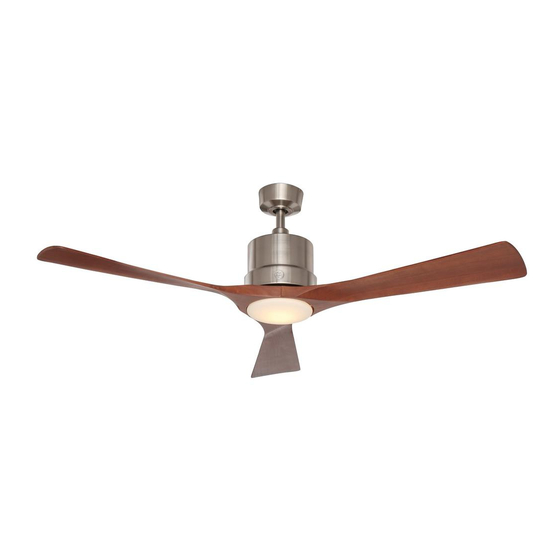
Phantom LED Ceiling Fan
54in (1.37m)
MODEL: 20338
120V 60Hz, MADE IN CHINA
Customer Assistance
1-866-885-4649
Contact a qualified electrician or call the Customer Care Service Team at 1-866-885-4649
Customer Service hours of operation are 9:00AM-5:00PM EST -Monday-Friday
customer. service@skyplug.com
Advertisement
Table of Contents

Related Manuals for GE 20338


Summary of Contents for GE 20338
- Page 1 User Manual Phantom LED Ceiling Fan 54in (1.37m) MODEL: 20338 120V 60Hz, MADE IN CHINA Customer Assistance 1-866-885-4649 Contact a qualified electrician or call the Customer Care Service Team at 1-866-885-4649 Customer Service hours of operation are 9:00AM-5:00PM EST -Monday-Friday...
-
Page 2: Safety Rules
Safety rules Read and Save These Instructions 1. To reduce the risk of electric shock, ensure electricity has WARNING: To reduce the risk of been turned off at the circuit breaker or fuse box before fire, electric shock or personal injury, mount fan to outlet box beginning. - Page 3 Basic guidelines for working with electricity 1. Before working on a circuit, go to the main service panel and remove the fuse or trip the breaker that controls that circuit. 2. Tape a sign to the panel warning others to leave the circuit alone while you work 3.
- Page 4 To begin / tools needed (not supplied) REQUIRED Flathead Phillips Screwdriver Safety Glasses Screwdriver (4" recommended) Pliers Wire Cutters Electrical Tape Step Ladder Wire Strippers Soft Cloth...
-
Page 5: Hardware Included
Hardware included Carefully unpack and identify each part to make sure you ATTENTION: Parts are not to scale. have everything ready for installation. Lay out each par t on a clean flat area such as a table or floor. Check to make sure NOTE: +1 = Extra quantity supplied you have the following: for future use if needed... -
Page 6: Package Contents
Package contents Carefully unpack and identify each part to make sure you ATTENTION: Parts are not to scale. have everything ready for installation. Lay out each part on a clean flat area such as a table or fl oor. (Parts AA-FF are pre-installed.) Check to make sure you have the following: Functional Fasteners PART... - Page 7 Fan installation drawing WARNING: Review important safety instructions before installation Outlet Box (Not Provided) Wood Screw (Long) Mounting Bracket Flat Washer Hot Wire - Black Spring Washer Receiver Mounting Screw Ground Wire from Mounting Bracket Plastic Wire Nut Antenna wire Neutral White Wire White Wire Ground Wire from the Fan Motor Assembly...
-
Page 8: Fan Installation
Fan installation INSTALLING THE MOUNTING BRACKET Remove the canopy cover (S) from the canopy (R) Use metal outlet box (sold separately) suitable by turning the canopy cov er (S) counter clockwise. for fan support. Secure outlet box directly to the building structure using wood screws (A) and star washers (C). -
Page 9: Hanging The Fan
Fan Installation HANGING THE FAN Remove the clevis pin (CC), Carefully feed the motor wires Align the holes at the bottom cotter pin (DD) and loosen 2 collar up through the downrod (T). of the downrod (T) with the holes set screws (BB) from the top of the Thread the downrod (T) into in the collar on top of the fan... -
Page 10: Preparing The Electrical Connections
Fan installation HANGING THE FAN WARNING: Failure to properly seat the tab in the groove could cause damage to wiring. Carefully lift the fan assembly Make sure the tab on the up to the mounting bracket mounting bracket socket is (Q) and sit the hanger ball / properly seated in the groove downrod assembly (T) in the... -
Page 11: Making The Electrical Connections
Fan installation MAKING THE ELECTRICAL CONNECTIONS WARNING: To avoid possible electric shock, be sure electricity is turned Motor to receiver electrical connections: Connect the black off at the main fuse box before wiring. wire from the fan to black wire marked “TO MOTOR L” from the receiver. -
Page 12: Attaching The Fan Blades
Fan installation ATTACHING THE FAN BLADES NOTE: Before starting installation, disconnect the power by turning off the circuit breaker or removing the fuse at fuse box. Turning power off using the fan switch is not sufficient to prevent electric shock. Remove and discard the preassembled plastic motor blocks and screws. -
Page 13: Remote Control Operations
Operation Instructions REMOTE CONTROL OPERATIONS In Case Of Interference with Several Fans, You Can Operate Fan using Transmitter Code Change the Transmitter Code to Operate This Fan Pre-Set by Factory Only. Step 1. Switch off the power of the fan. Step 1. -
Page 14: Remote Functions
In the unlock position : The transmitter will send a common code, this transmitter will operate all other GE FANS with the same receiver configuration. But the condition is the receiver has been pre-synced with the common code, otherwise the fan will not work. - Page 15 Remote Control Pairing Instructions REMOTECONTROLPAIRINGINSTRUCTIONS Important Note : By default, every fan has been pre-programmed at the factory and should be fully functional once installation is completed. There is no need to perform the pairing process. Should you find the fan or remote control not working or not fully functional after installation or during use, pairing of the remote control can be done by following the below simple procedures.
-
Page 16: Blade Balancing
Blade balancing The following procedure should correct most fan wobble. Check after each step. Check that all blade and blade bracket screws are secure. Most fan wobble problems are caused when blade levels are unequal. Check this level by selecting a point on the ceiling above the tip of one of the blades. - Page 17 Blade balancing kit The balancing kit should only be used if there is an unacceptable amount of fan wobble after completing all the steps in the user manual under “Attaching the Fan Blades”. Attach the plastic clip on blade 1. Turn the fan on and set the speed control setting to a speed at which the wobble is the greatest.
-
Page 18: Safety Instructions
Safety Instructions WARNING: Make sure the power is PRODUCT MAINTENANCE off at the electrical panel box before you attempt any repairs. Refer Here are some suggestions to help you maintain your fan. to the section “Making Electrical Connections.”, page 11. Because of the fan’s natural movement, some connections may become loose. -
Page 19: Manual Del Usuario
Manual del Usuario Ventilador de techo LED Phantom 54pulg. (1.37m) Modelo: 20338 120V 60Hz, HECHO EN CHINA Atención al cliente 1-866-885-4649 Comuníquese con un electricista cali cado o llame al Servicio de Atención al cliente al 1-866-885-4649 El horario del Servicio de Atención al cliente es de 9:00 a. m. a 5:00 p. m. EST, de lunes a viernes. -
Page 20: Para Su Seguridad
Para su seguridad Lea y Guarde estas Instrucciones ADVERTENCIA: Para reducir el 1. Para reducir el riesgo de descarga eléctrica, asegúrese de riesgo de incendios, descargas que la electricidad se hay a apagado en el disyuntor o caja de eléctricas o lesiones personales, fusibles antes de comenzar. - Page 21 Para su seguridad 1. Antes de trabajar en un circuito, vaya al panel de servicio principal y retire el fusible o active el disyuntor que controla ese circuito. 2. Pegue una señal en el panel que advierta a otras personas que se ale jen del circuito mientras usted trabaja 3.
- Page 22 Herramientas Necesarias (no suministradas) NECESARIO Destornillador de Destornillador de Gafas de seguridad cabeza plana estrella (4” recomendado) Alicates Cortadores de Cinta eléctrica cable Escalera Pelacables Paño suave...
-
Page 23: Herrajes Incluidos
Herrajes incluidos Desempaque con cuidado e identifique cada una de las ATENCIÓN: Las piezas no están a piezas para que se asegure de que tiene todo listo para la escala. instalación. Coloque todas las piezas en una superficie limpia y plana, como una mesa o alfombra. Revise para asegurarse NOTA: +1 = Cantidad extra provista de que tiene lo siguiente. -
Page 24: Contenidos Del Paquete
Contenidos del paquete Desempaque con cuidado e identi que cada una de las piezas ATENCIÓN: Las piezas no están a escala. para que se asegure de que tiene todo listo para la instalación. Coloque todas las piezas en una super cie limpia y plana, como una mesa o alfombra. - Page 25 Dibujo de la instalación del ventilador ADVERTENCIA: Revise las instrucciones de seguridad importantes antes de la instlación. Caja electrica (no suministrada) Tornillo para madera (largo) Soporte de montaje Arandela plana Cable blanco de alimentación Arandela de resorte Receptor Tornillo de montaje Cable de puesta a tierra del soporte de montaje Tuerca de plástica para cable Cable de antena...
- Page 26 Instalación del ventilador INSTALACIÓN DEL SOPORTE MONTAJE Utilice la caja eléctrica metálica (se vende por Retire la cubierta del orón (S) del orón (R) separado) adecuada para el soporte de ventilador. girándola en sentido antihorario. Asegure la caja eléctrica directamente a la estructura de construcción utilizando tornillos para madera (A) y arandelas de est rella (C).
-
Page 27: Colgar El Ventilador
Instalación del ventilador COLGAR EL VENTILADOR Alinee los agujeros de la parte Quite el pasador de horquilla (CC), el Cuidadosamente meta los cables del de debajo de la varilla (T) con los pasador de aletas (DD) y los 2 tornillos motor a través de la varilla (T). - Page 28 Instalación del ventilador CÓMO COLGAR EL VENTILADOR ADVERTENCIA: El hecho de no colocar correctamente la lengüeta en la ranura podría provocar daños al cableado. Levante con cuidado el Asegúrese de que la lengüeta conjunto del ventilador hasta el de la ranura del soporte soporte de montaje (Q) y coloque de montaje esté...
-
Page 29: Cómo Hacer Las Conexiones Eléctricas
Instalación del ventilador ADVERTENCIA: Para evitar posibles CÓMO HACER LAS CONEXIONES ELÉCTRICAS descargas eléctricas, asegúrese de que la electricidad esté apaga da en la caja Conexiones eléctricas del motor al receptor: Conecte el cable de fusibles principal antes de realizar negro del ventilador al cable negro marcado “AL MOTOR L”... - Page 30 Instalación del ventilador CÓMO COLOGAR LAS ASPAS DEL VENTILADOR NOTA: Antes de comenzar la instalación, desconecte la energía apagando el disyuntor o retirando el fusible de la caja de fusibles. Apagar la energía utilizando el interruptor del ventilador no es suficiente para evitar una descarga eléctrica.
-
Page 31: Instrucciones De Operacion
Instrucciones de Operacion Paso 1. Apague el interruptor del ventilador. Paso 1. Restablezca la electricidad del ventilador. Paso 2. Encienda el interruptor del ventilador. Paso 2. Instale dos baterías AAA de Paso 3. Durante los primeros 30 segundos, 1,5 -vatios provistas. mueva el interruptor de seguridad en la parte de atrás del transmisor poniéndolo en la posición de Paso 3. - Page 32 -Cuando el interruptor de bloqueo / desbloqueo está en la posición de desbloqueo , permite que se envíe un código común. El transmisor emitirá un código común, el transmisor podrá operar otros ventiladores GE con la misma configuración del receptor, de lo contrario el ventilador no funcionará.
- Page 33 INSTRUCCIONSE PARA LA SINCRONIZACIÓN CONTROL REMOTO INSTRUCCIONSEPARALASINCRONIZACIÓNDELCONTROLREMOTO Nota Importante: De manera estandar cada ventilador ha sido configurado en la fábrica y debe funcionar sin problemas una vez este haya sido instalado completamente. No se require el processo de sincronización. Si encuentra que el ventilador o el control remoto no funciona completamente después de la instalación o durante su uso, la sincronización del control remoto puede hacerse siguiendo los pasos a continuación.
- Page 34 Equipo de balanceo El siguiente procedimiento debe corregir la may or parte del tambaleo del ventilador. Compruebe después de cada paso. Compruebe que todos los tornillos de las aspas y de los sopo rtes de las aspas estén asegurados. La may oría de los problemas del tambaleo se originan cuando los niveles de las aspas son desiguales.
- Page 35 Equipo de balanceo El kit de balanceo de las aspas solo se debe usar si hay tambaleos del ventilador luego de haber terminado todos los pasos de la instalación del ventilador en el manual bajo "Colocación de las aspas" 1. Encienda el ventilador y póngalo en la velocidad donde el tambaleo es mayor.
-
Page 36: Solucion De Problemas
Intrucciones de Seguridad CUIDADO DE SU VENTILADOR Aquí hay algunas sugerencias para ayudarle a mantener su ventilador. Debido al movimiento natural del ventilador, algunas conexiones pueden aflojarse. Compruebe las conexiones de soporte, enchufes y adjuntos de las aspas dos veces al año. Asegúrese de que no están flojos.