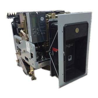
GE AKR-30S Manual
Akr series, low voltage power circuit breaker
Hide thumbs
Also See for AKR-30S:
- Installation and maintenance instructions manual (40 pages) ,
- Manual (63 pages) ,
- Installation instructions manual (28 pages)
Table of Contents
Advertisement
Advertisement
Table of Contents

Related Manuals for GE AKR-30S


Summary of Contents for GE AKR-30S
-
Page 2: Table Of Contents
Tabl e of Contents Description Page Introduction Quick Selector Breaker I Trip Combinations ....Quick Selector Replacement Breakers Breaker I Trip Combinations ......4 Breaker Designations Legend . - Page 3 Built to withstand intense service conditions, these circuit breakers provide AKR-50, AKRT-50, AKR-75 and AKR-1 00; 800 through 4000 Amperes with short circuit ratings through 200,000 for the ultimate in system selectivity due to their short time Amperes. AKR-50 AKR-75 AKR-30S ,'\KR-30H...
- Page 4 Selector Breaker Trip Con:b1nations 250Vdc Electromechanical Frame Breaker Solid State Trip Device Trip Device Size Ty p e AKR-30S AKR-30, 30H AKR-50, -50H 1 600 2000 AKRT-50H 2000 AKR-75 3200 4000 6000 AKR-100 4000...
- Page 5 Quick Sel ector Repl acement Breakers Breaker Trip Device Combinations Table 4.2 Ampere Ratings and Overcurrent Trip Devices 250Vdc 600V ac 5 0 /60 Frame Breaker Solid State Electromechanical Size Trip Device Type Trip Device AK-25 AKS-50 1 600 2000 AKST-50 2000 AKR-75...
- Page 7 This circuit breaker is closed by first rotating the handle counterclockwise approximately 1 00 degrees; this resets the mechanism and partially charges the closing spring. Return ing the handle clockwise to the normal position completes the spring charging and drives the toggle mechanism over center, closing the contacts.
- Page 8 Features and Characteristics �lectrical Ooerat1on Electrical Storeti f.ne�gy -\K-25 and AKRiU)<30S This electrically operated breaker closes whenever the closing solenoid coil is energized. This causes an upward movement of the solenoid armature which charges the springs to a predetermined over-center point for closing. (For typical electrical circuit see pg.
-
Page 9: Type Akru Breakers
Type AKRU Breakers as an integral part of the ary mounted fused breakers The fused low voltage power device trips the breaker, drouHbffia�r mee�NEMA fused draw out breakers in are not available.) opening all three poles standard SG3 and ANSI Ampere An open fuse lock out simultaneously. -
Page 10: Enclosures And Mountings
Enclosures and Mountings Metal-Enclosed Low Voltage Power Circuit Breaker AKD-8 Switchgear AKD-8 Type draw out LVPCB's are furnished in low voltage switchgear with integrated short circuit ratings. The equip N EMA ANSI ment is designed, manufactured and tested to SG5, C37.20.1 and UL1558. - Page 11 UL necessary to outfit a com and through the compart secondary disconnects partment for closed-door ment door on the AKR-30S, Iisted to ANSI C37. 1 6 stand remain engaged. This per ards. The substructure is the draw out AKR breakers.
- Page 12 Draw Out General Purpose Enclosure- NEMA 1 For indoor use, the one-high The draw out mechanism closed door draw out steel is externally operated by a housing is complete with a removable racking handle. draw out breaker (draw out Two mechanism types mounting type letter "/\').
- Page 13 The RMS-9 MicroVersaTrip Therefore, the solid state that cause non-sinusoidal the protection programmer. system for AKR low voltage microprocessor is not af currents. The low energy signal from power circuit breakers ? On fected by component toler the programmer counteracts A FuH Function lnp Unit sists of four parts: plug-In the strength of a permanent...
- Page 14 Power Supply Board Programmer Faceplate Logic Board XFMR GROUND FAULT .--- -- -. SIGNAL IL P SWITCHES TRIP COMPARATOR Ep1c MicroVersaTrip'" IOC TRIP FLUX Board (when used) INST SHIFTER SWITCH MicroVersaTnp" RMS-9 blocK diagram.
-
Page 15: Trip Devices
Trip Devices Micro Versa Trip RMS-9 Programmer Tripping Functions 1 . Current Setting -Standard 2. Long-Time Delay -Standard 3. Long-Time Pickup Light -Standard Short-Time Pickup -Optional 5. Adjustable Short-Time Delay-Optional 6. Instantaneous Pickup -Standard 7. Ground Fault Pickup -Optional 8. Ground Fault Delay -Optional 9. - Page 16 All pickup tolerances ® Time delay shown at lower limit of Current setting are± 10%. @ For AKR-30S only. each band. Ground fault pick up Short-time rating Table 15.2 MicroVersaTrip® RMS-9 Programmer-Available Combinations (Add Suffix to Basic Catalog Number) GF®...
- Page 17 Trip Devices MicroVersaTnp" RMS-9 Tripping Functions Long-Time Functio n CURRENT SETTING Moving from left to right on the current axis, Figure 1 6.1, the upper part of the time current curve is the long time pickup. This is the func tion used to protect a circuit 1 1X against low magnitude over...
- Page 18 Function Ground Fault Protection � 1000 An Ft function is available A ground fault is uninten '" '" "' with MicroVersaTrip.® This tional current flowing from a "' f-+-++-I'H-- -+- --t--- 1 provides a ramp function circuit through a conducting GROUND FAULT Wt =constant) in the short...
- Page 19 Type AKR Breakers Tri p Devices MicroVersaTrip RMS-9 Tripping Functions Current Setting (Standard) The adjustable current CURRENT SETTING setting determines the nominal long time current setting with a ± 1 0% band width . With a 1 . 1 setting the breaker will carry indefinitely without tripping the rating 1.1X...
- Page 20 Short-Time Delay (Optional) The short-time delay adjust ment is used in conjunction with the short-time pickup setting to provide a further refinement of coordination SHORT TIME DELAY between circuit breakers. It 1 2 T IN 1 2 T OUT MAX MAX establishes the time interval .: : ' ®...
- Page 21 Tri p D evices Continued Includes adjustable short short-time rating permitting High Range Instantaneous time pickup, adjustable maximum use of the short-time delay and a high breaker's short-time capa level instantaneous setting bility. This high level instan is adj ustable in four steps taneous function increases from 40 to 1 00 percent of system protection without...
- Page 22 Fault Trip Indicators Indicators are designed to reduce system downtime by OVERLOAD SHORT CIRCUIT GROUND FAULT analyzing any overcurrent © © © fault and identifying its cause. Mechanical pop-out type indicators are available on the programmer for TRIP INDICATOR identifying overload or PUSH TO short circuit overcurrent RESET...
-
Page 23: Ec Trip Devices Dc Applications
Tri p Devices EC Trip Devices DC Applications General Long-Tim e Delayis lnstantaneoustripping is mounted in each breaker Type EC overcurrent trip is obtained when a tension accomplished with a pole and contains functional devices are magnetically positive-displacement oil spring yields to the force adjustments, overcurrent operated, using a series coil piston. -
Page 24: Accessories
Accessories Shunt Trip The shunt trip offers remote electrical tripping of breaker. It is usually controlled by a switch or pushbutton and may also be used in conjunction with protective relays for automatic tripping. The shunt trip coil is rated for intermittent duty. When factory installed it is supplied with a cutoff switch which automatically removes control power following a breaker trip. - Page 25 Accessories Continued Auxiliary Switch The auxiliary switch is used for remote indication of breaker main contact position. It is available in groupings of tour contacts (two stages) or ten contacts (five stages). Each stage is composed of one "a" Type (N .O.) contact and one "b"...
- Page 26 Fuse Roll Out Close Button The AKR-75 and -1 00 draw out AKRU breakers require a The AKA electrically operated breaker is furnished as separate fuse roll out. All fuse roll outs accept Class L fuses standard without operating handle and is closed by receipt of 800-4000A .
-
Page 27: Oem Substructure
Accessori es OEM Substructure Secondary Disconnects Fourth Wire Disconnect Breakers may be ordered with up to twenty-one draw Fourth wire disconnect kits for use when three phase, four wire ground fault protection is required provides for connec out control disconnect points furnished in groups of seven. Seven circuit disconnect block kits and mounting brackets tion to fourth wire neutral sensor. - Page 28 "T" Connector 200UA (For 1600A and 2000A substructures.) Provides alternate means for bus connecting to the substructure. Current Transformer Mounting Hardware Provides the necessary mounting hardware for mounting applicable current transformers in the substructure. Programmer Secondary Disconnect Shutter Ki t Required when programmer on breaker has zone selective Shutters to cover primary disconnects when breaker is interlocking .
-
Page 29: Ratings
®Observe Table 5 minimum overcurrent trip ratings. ® Only dual ratio sensors are available on AKR-30S when programmers are furnished with High Range Instantaneous or Triple Selective Trip. Triple Selective Trip at 1 X short-time rating when standard Instantaneous Trip is omitted. -
Page 30: Derating Factors
Derating Factors Tem perature Table 29. 1 Continuous Current Derating Factors Class A insulation. Continu Derating Factors ous current ratings of AKR Derating Factor Ambient Temperature breakers must be derated for The continuous current 40°C 1 . 00 ambient temperatures above rating of AKR breakers is 45°C 40°C. -
Page 31: Akr-30S
<D Sensor Ampere Rating Sensor Turns Ratio Current at Rated Input Current Fixed 1 50 750 : 1 AKR-30S 4000 : 1 AKR-30 , 30H 200 mA 1 600 8000 : 1 AKR-50 , AKRT-50H 2000 1 0000 : 1... - Page 32 2000 2000 2000 GF30W8 A4BX800 2500 STD GF8B2500 A4BY2500 1 000 GF30W10 A4BX1 000 BG 2500 SPEC GF9F2500 AK A4BX2500 GE 1200 GF30W12 A4BX1 200 BG 3000 GF8F3000 A4BY3000 ® 1 600 GF30W1 6 A4BX1 600 BG 4000 GF8F4000 A4BY4000 @...
-
Page 33: Outline Drawings
Outline Drawi ngs Continued 50 M a n u al AKR - ( )S � ... TM\So 'T'&JitM1�"" l$0ti.I'TT'I.D 01>.1. AUXILI.t.ll: '( Sir.(\� 2. f'II:M.&. D.L M,.UK.!.R ::;,o" C::. .. K A.I<G� !=OR A � \Qo(E. --.vE&&& �lltl'l� loll"'f� - 140" -;: o lit �... - Page 35 Outl ine Drawings Continued Draw Out Breaker Substructure Drawings Substructure outline d rawings shown are for breakers with MicroVersaTrip® RMS-9 trips. Refer to page 57 for a complete list of other outlines available. (AKR-308) (10) HOlE LOCATIONS FOR ' 1 ..-20 80I.TS NOTE #1-TtESE POSTS M' BE RE11MD TO STRAP...
- Page 36 � ... _ _ _ ____ _ i.,._ _ __ _ C1'� 4kC. 1 /SCilUfl'+'�t:. r ...,_ S .I T / � .14/ C / � .eK .e..Z'I'SC<I!) N # Et:.T .Pfi!) $ /T/D.A/ 2 "' - 2 S...
- Page 37 Outl ine Drawings Continued AKR-75, -100 - - --< 28.l S --- J(.I/1!!1 -"" T'l:F $�. .: = = = � .::. -::: ::. -::. � � p 2 .3-�00 ,5-i'EA.I:'C£ .. t:. 0$Z at/r NOVT / N .ST AI.. t. CO .
-
Page 38: Outline Dimension Drawing Numbers
Outli n e D i m ension D rawing N u mbers Dimension Drawing Draw Out Dimension Drawing Number Substructure Number AKR-6D-30S Manual, Electric 1 39C5317 TAK1 SR01 75C1 49359 AKRU-6D-30S Manual, Electric 1 39C5318 TAK1 SR01 F 75C1 49359 AKR-6s-30S Manual, Electric 139C5319 TAK1SR02... -
Page 39: Weights And Formulas
Weights and Formulas Ta ble 54. 1 ShiPPing We1 ghts i \ t)s Draw Out Shipping Breaker Electrical Element Manual Electrical Manual AKR-30S 1 00 AKRU-30S 1 1 0 1 00 1 20 AKR-30 AKRU-30 AKR-50 21 0 21 5... - Page 40 Circuit breakers are cations. Industry standards under usual service condi column heading must designed primarily to per have been established tor tions, shall be capable of be given consideration . form the function of circuit the m inimum performance operating the number of This standard applies to all interruption under short...
- Page 42 Fig. 5 7 . 1 Fig . 57 . 2 T rans: : 50kVA , 480V, 5.75 % Z T ransf: 750kVA , 6 00V, 5.75%Z 2 4,000 I B,OOO if> if> 22,000 1 6 ,000 20,000 <t <t ;;!: 1 4,000 1 8,000 >-...
-
Page 43: Transformer Short Circuit Current Curves
Transformer Short Circuit Cu rrent Cu rves Continued F i g . 58 1 Tra n s f : 1 5 0 0 1\VA ·i.75%Z 30,000 90,000 <f) <f) "' � 80,000 80,000 " "' <t <t � � 70,000 70,000 >- >... - Page 44 ,., , ,_ • 1 c3n Na' · : of E t ec.trica: and National Electrical Code Stan d. :J :'"ds J r��- fV1 a n u fact u rers Asso c i a� ior· E i E ctrnnics (NEMA) (IEEE) In Enclosures, Low-Voltage 1 984 1ssue.
-
Page 45: Guide Form Specifications
Portable MicroVersaTrip RMS-9 test kit Other Circuit Breaker Publ ications Testing Instructions General Installation and Maintenance MicroVersaT rip T est Set TVTS1 AKR-30S, AKRU-30S G EK-64464 G E �)-5019 ECS/SST T est Set T AK-TS2 AKR-30/50/T50 G EK-73300 G EK-64459...