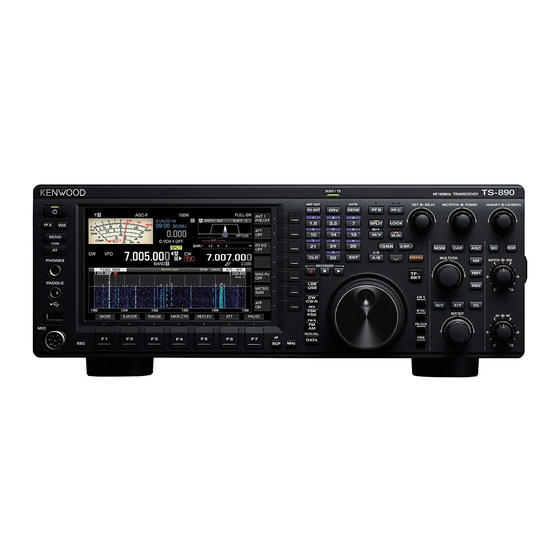
Kenwood TS-890S Instruction Manual
Hide thumbs
Also See for TS-890S:
- Instruction manual (196 pages) ,
- In-depth manual (96 pages) ,
- Command reference manual (77 pages)
Table of Contents
Advertisement
Advertisement
Table of Contents

Related Manuals for Kenwood TS-890S


Summary of Contents for Kenwood TS-890S
- Page 1 TS-890S INSTRUCTION MANUAL B5A-2215-00 (K, E)
-
Page 3: Connection
Provides third-order intermodulation DR: 110 dB, RMDR: 112 software. dB and BDR**: 150 dB (Measurement example at 2 kHz A user is required to obtain approval from JVC KENWOOD detuning: RX frequency 14.2 MHz, MODE CW, BW 500 Hz, ●... -
Page 4: Configuration
JVC KENWOOD Corporation is entirely free from any responsibilities arising from any losses for JVC KENWOOD Corporation and the respective bona fide or damages caused by such typos or expressions. holder. -
Page 5: Timer
Immediately turn the power OFF and remove the power If you accidentally damaged the LCD display and the liquid in ● cable. Contact a KENWOOD service station or your dealer for the LCD display splashes and gets into your eyes or mouth, advice. -
Page 6: Operation
JVC KENWOOD. The user could lose byproducts. the authority to operate this equipment if an unauthorized Contact your local authority for details in locating change or modification is made. -
Page 7: Table Of Contents
CONTENTS CONTENTS BEFORE USING Configuring the Number of Steps per Revolution of the Tuning Control ......................4-5 CONTENTS Configuring the Fast Forward Rate of the Tuning Control ....4-5 Configuring the Sensitivity for Starting the Fast Forward Operation 4-5 1 INSTALLATION AND CONNECTION Frequency Adjustment Using the [MULTI/CH] Control .... - Page 8 CONTENTS Preamplifier ..................5-6 Saving RTTY Communication Logs ..........5-18 RX Monitor ..................5-6 Adjusting the RTTY Decode Threshold Level ....... 5-18 SWL (BCL) Mode ................5-6 FFT Scope/X-Y Scope Display Setting ......... 5-18 Band Switching in the SWL Mode (VFO Mode) ......5-6 FFT Scope Waveform Averaging ..........
- Page 9 CONTENTS Configuring the Tone Frequency ..........5-29 Marker Shift ..................7-2 Tone Frequency Scan ............... 5-29 Shifting the Marker ..............7-2 CTCSS Operation ................. 5-30 Changing the Shift Position of Marker Shift ......... 7-3 Selecting CTCSS ..............5-30 Expand .................... 7-3 Configuring the CTCSS Frequency ...........
- Page 10 CONTENTS Adjusting the TX Equalizer .............. 8-6 Registering a Name for a Voice Message ........12-1 Copying the TX Equalizer Settings ..........8-6 Playing Back a Voice Message ............. 12-2 Saving the TX Equalizer Settings ............ 8-6 Adjusting the Playback Volume ............. 12-2 Reading the TX Equalizer Settings ..........
- Page 11 Configuring the Key Repeat Speed ..........16-5 Starting Sky Command System II Operation ....... 16-17 Saving a Screen Shot ............... 16-6 TS-890S + TH-D7A/ TH-D72(A/E)/ TM-D700A/ TM-D710/G(A/E)/ Configuring Output to an External Meter ........... 16-6 TM-V71A + RC-D710 (Transporter) Setup ......16-17 Configuring the Output Signal Format of the External Meter ..
-
Page 13: Installation
1 INSTALLATION AND CONNECTION INSTALLATION AND CONNECTION 1 Installation Installation of Lightning Arrestors • To prevent fire, electric shock, malfunctioning and injury due to Do not lift this transceiver by holding the Tuning control lightning, install a coaxial lightning arrestor. ●... -
Page 14: Torque Adjustment With Tuning Control
1 INSTALLATION AND CONNECTION Torque Adjustment with Tuning Control Paddle (PADDLE) ■ For CW operation using the built-in electronic keyer, connect a The Tuning control allows the rotational torque (weight) to be keyer paddle to the PADDLE jack. A Φ6.3 mm three-pronged plug adjusted according to the user’s preference. -
Page 15: Connection Of Accessories (Rear Panel)
INSTALLATION AND CONNECTION 1 Connection of Accessories (Rear Panel) USB Flash Drive/USB Keyboard ( ■ For connecting a commercially available USB flash drive or USB A cable exceeding 3 m (9.8 feet) may not be connected keyboard. ● to a connector below. Plug the USB flash drive or USB keyboard firmly into the •... -
Page 16: Connection With Data Communication Equipment
8-1.) Before connecting this transceiver with a PC using a USB cable, download also a virtual COM port driver and install it on the PC. http://www.kenwood.com/i/products/info/amateur/software_download.html • When using an ACC 2 connector: connect the audio output line of the PC to pin 11 (ANI) of the ACC 2 connector and the audio input line of the PC to pin 3 (ANO). -
Page 17: Terminal Descriptions
INSTALLATION AND CONNECTION 1 Terminal Descriptions COM Connector Pin No. Pin Name Function Input/Output No connection — Sends serial data to PC. Receives serial data from PC. No connection — Signal ground — No connection — Sends signal from the PC to this transceiver. If the PC is unable to accept incoming data, an “L” level signal is output from the PC to this transceiver and data will not be sent in this case. -
Page 18: Front Panel
1 INSTALLATION AND CONNECTION ACC 2 Connector Pin No. Pin Name Function Input/Output — No connection — RTTY RTTY control terminal (FSK key input) Audio output • Connect to the audio input of the TNC, MCP or PC (or PC connection interface). •... - Page 19 INSTALLATION AND CONNECTION 1 EXT. AT Connector Pin No. Pin Name Function Input/Output Signal ground — EXT.AT connector (TTI/TTO) Signal ground — No connection — EXT.AT connector (TSI/TSO) DC 13.8 V power supply for EXT.AT MIC Connector Pin No. Pin Name Function Input/Output MIC signal input...
-
Page 21: Panel Key Behavior
2 NAMES AND FUNCTIONS OF PARTS NAMES AND FUNCTIONS OF PARTS 2 Front Panel Panel Key Behavior Behavior Refer to Press Turns on the power. Press and Turns off the power. hold Press [PF A] Activates the registered function. 16-2 Press and hold Press... -
Page 22: Manual Recording
2 NAMES AND FUNCTIONS OF PARTS Behavior Refer to [CW T.] Press Activates the CW auto tune function. Press Switches between receiver (RX) filters A, B and C. [IF FIL] Press and Displays the RX Filter screen. hold [FIL CLR] Press Restores the passband of the RX filter that has been changed to the preset value. - Page 23 NAMES AND FUNCTIONS OF PARTS 2 Behavior Refer to Displays the memory channel list screen. M.IN] Press Registers a memory channel. Switches the menu mode item. Registers a quick memory channel. [<Q-M.IN] Press Switches the menu mode item. Calls up a quick memory channel. Press Switches the menu mode item.
-
Page 24: Program Scan
2 NAMES AND FUNCTIONS OF PARTS List of Function Key Behaviors (Standard Mode Screen) Function Keys (Vertically Arrayed) Key Guide Behavior Refer to Press Switches the preamplifier. (OFF/ PRE 1/ PRE 2) [ANT/PRE] Press and Switches between “ANT 1” and “ANT 2”. 4-10 hold Press... -
Page 25: Quick Memory Channels
NAMES AND FUNCTIONS OF PARTS 2 List of Control Knob Behaviors Control Behavior Refer to Tuning Aligns the TX and RX frequencies. Switches the frequency at a fast speed. (Available in the VFO mode.) Switches the channel number. (Available in the memory channel and quick memory channel [MULTI/CH] modes.) Switches the item to configure or configured value. -
Page 26: Screen
2 NAMES AND FUNCTIONS OF PARTS List of LED Behaviors Behavior When power is OFF: light off When power is ON: lights up in green [POWER] When power is OFF with timer activated: lights up in orange When timer is starting up: blinks in orange [VOX] Lights up when the VOX function is enabled. -
Page 27: Rear Panel
For connecting an external speaker. Connector for connecting a PC or LAN when running with the KNS <LAN> Connector (KENWOOD NETWORK COMMAND SYSTEM) or for automatic correction of the clock time. DVI-I connector for connecting an external monitor. Both analog <DISPLAY>... -
Page 28: Microphone (Optional)
2 NAMES AND FUNCTIONS OF PARTS Microphone (Optional) A PTT (Push-to-talk) Switch Switches to the transmitting state while this switch is being pressed. Releasing the switch restores the transceiver to the receiving state. B UP/ DOWN Keys For scrolling up/down the items in one of the following modes, such as scrolling up/down the VFO frequencies. Pressing and holding down the key enables continuous scrolling. -
Page 29: Preamplifier
NAMES AND FUNCTIONS OF PARTS 2 Screen Ⓐ Ⓑ Ⓒ Ⓓ Ⓔ Ⓕ Ⓖ Ⓗ Ⓘ Ⓙ Refer Area Display Description Appears when an RX antenna is functioning. 4-10 Displays the antenna number. Switches the antenna number accordingly when the antenna is switched. -
Page 30: Noise Blanker
2 NAMES AND FUNCTIONS OF PARTS Refer Area Display Description Appears when the RIT function is enabled. Appears when the XIT function is enabled. Displays the RIT or XIT frequency (between -9.999 and 9.999 kHz). Appears according to the input path of the TX audio selected by the data VOX function. OFF: Appears when sound is not input from all paths. - Page 31 NAMES AND FUNCTIONS OF PARTS 2 Refer Area Display Description Displays the mode that is currently running. “-D” is displayed when in the data mode. Appears while receiving in the TX band. – Appears while transmitting in the TX band. “-R” is displayed when in the reverse mode. Appears when configuring the frequency of the VFO mode or auto mode.
- Page 32 2-12...
-
Page 33: Usb/File Management Menu Screen
3 MENU MENU 3 7 Press F1 [ Menu Operation ] or [<Q-M.IN]. The selected content is confirmed. 8 Press [MENU] or [ESC] to exit the menu screen. The settings of the different functions of this transceiver can be changed from the menu. It can also be used to switch the operating In the subsequent descriptions on the menus, the expression environment. -
Page 34: Decoded Character Output
3 MENU Common Menu Screen Operations Switching between the CONFIG A and CONFIG B Operating Environments • Pressing F [MENU TOP] returns the menu screen to the top. • Pressing F [GROUP ]/ F [GROUP ] switches the “Operating environment” refers collectively to values configured in the menu as well as the different settings data for operation. -
Page 35: Menu Items
MENU 3 Menu Items Menu - 0. Basic Configurations - Menu Display Description Setting Value Default Refer to Display 0-00 Color Display Pattern Display color type Type 1/ Type 2/ Type 3 Type 1 0-01 Function Key Style Type of function key display Type 1/ Type 2/ Type 3 Type 1 Font 1/ Font 2/ Font 3/ Font 4/ Font... -
Page 36: Voice Guidance
3 MENU - 0. Basic Configurations - Menu Display Description Setting Value Default Refer to Display Function assignment to [PF 2] on Refer to PF (Programmable 0-27 Microphone PF 2: Key Assignment SPLIT 16-2 the microphone Function). Function assignment to [PF 3] on Refer to PF (Programmable 0-28 Microphone PF 3: Key Assignment... -
Page 37: Program Slow Scan
MENU 3 - 3. Controls Configurations - Menu Display Description Setting Value Default Refer to Control Rate Frequency Rounding Off (Multi/ Channel Rounds off the frequency of the 3-00 Off/ On Control) [MULTI/CH] control SSB Mode Frequency Step Size (Multi/ 3-01 SSB frequency step size 0.5/ 1/ 2.5/ 5/ 10 [kHz]... -
Page 38: Audio Recording In Tandem With Squelch
3 MENU - 5. CW Configurations - Menu Display Description Setting Value Default Refer to Weight and Timing Automatic CW TX with Keying in SSB CW transmission by keying in the 5-06 Off/ On Mode SSB mode Carrier frequency correction Carrier Frequency Offset (SSB Mode to 5-07 when shifting from the SSB mode... -
Page 39: Waterfall Display During Tuning (Center Mode)
MENU 3 - 7. Rear Connectors - Menu Display Description Setting Value Default Refer to Baud Rate 4800/ 9600/ 19200/ 38400/ 57600/ 7-00 Baud Rate (COM Port) Baud rate of COM connector 9600 [bps] 16-5 115200 [bps] Baud rate of virtual COM 9600/ 19200/ 38400/ 57600/ 7-01 Baud Rate (Virtual Standard COM) -
Page 40: Meter
3 MENU Advanced Menu Items Menu Display Description Setting Value Default Refer to Automatic/ TX Power/ ALC/ Drain Indication Signal Type (External Target of external meter output 1 Voltage (Vd)/ Compression Level TX Power 16-6 Meter 1) (COMP)/ Current (Id)/ SWR Automatic/ TX Power/ ALC/ Drain Indication Signal Type (External Target of external meter output 2... - Page 41 MENU 3 Linear Amplifier Menu Items Display Description Setting Value Default Refer to Band Target bands of the linear amplifier menu HF/ 50M/ 70M (E type) Linear Amplifier Linear amplifier ON/OFF Off/ On Keying Logic Linear amplifier TX control Active Low/ Active High Active Low TX Delay Linear amplifier TX delay ON/OFF...
- Page 42 3 MENU Clock Menu Items Menu Display Description Setting Value Default Refer to 0.Date and Time Year: '18 (2018) to '99 (2099) Month: JAN/ FEB/ MAR/ APR/ Year: '18 0-00 Date (Local Clock) Date of the local clock MAY/ JUN/ JUL/ AUG/ SEP/ OCT/ Month: JAN NOV/ DEC Day: 01...
-
Page 43: Built-In Voip Function
MENU 3 Display Description Setting Value Default Refer to Programmable Timer Frequency during program timer 30.000 kHz to 59.999.999 MHz 14.000.000 operation LSB/ USB/ CW/ CW-R/ PSK/ PSK- Frequency/Mode 14-3 R/ FSK/ FSK-R/ FM/ AM/ LSB- Mode during program timer operation DATA/ USB-DATA/ FM-DATA/ AM-DATA Sleep Timer... - Page 44 3-12...