
Related Manuals for Lars Thrane LT-3100


Summary of Contents for Lars Thrane LT-3100
- Page 1 User & Installation Manual LT-3100 Satellite Communications System Document Number: 95-100765 Rev. 1.02 Release date: May 29, 2018 Copyright © Lars Thrane A/S Denmark ALL RIGHTS RESERVED...
- Page 3 Manuals issued by Lars Thrane A/S are periodically revised and updated. Anyone relying on this information should acquire the most current version e.g. from Lars Thrane A/S. Lars Thrane A/S is not responsible for the content or accuracy of any translations or reproductions, in whole or in part, of this manual from any other source.
- Page 4 Failure to comply with these precautions or with specific warnings elsewhere in this manual violates safety standards of design, manufacture and intended use of the equipment. Lars Thrane A/S assumes no liability for the customer's failure to comply with these requirements. Instructions for the Operator...
- Page 5 LT-3100 User & Installation Manual Rev. 1.02 Required information for the reader Throughout this document, essential information will be presented to the reader. The following text (emphasized) has the following meaning and/or implication: WARNING: A ‘Warning’ is an Operation or Service procedure that, if not avoided, may cause a hazard situation, which could result in personnel death or serious injury.
-
Page 6: About This Manual
About this manual Intended readers This is a User & Installation Manual for LT-3100 Satellite Communications System, or LT-3100 system. The manual is primarily intended for installers and service personnel. Personnel installing or servicing the system should be professionals with technical expertise, properly trained, and likewise authorized. - Page 7 LT-3100 User & Installation Manual Rev. 1.02 Software versions This manual is applicable to the following software: Software Versions Description Version LT-3100 system 1.01 Table 1: Software Versions Lars Thrane A/S www.thrane.eu...
- Page 8 LT-3100 User & Installation Manual Rev. 1.02 Record of Revisions Rev. Description Release Date Initials 1.00 Original document. January 12, 2018 1.01 Document updated with editorial corrections. January 17, 2018 As a result of the certification completed, the following sections are updated: 1.02...
-
Page 9: Table Of Contents
LT-3100 User & Installation Manual Rev. 1.02 Table of Contents Introduction ............................... 1 Unpacking (in-the-box) ............................2 Inspection ..............................2 Accessories ................................ 3 Mounts ................................3 Cable and connectors ............................ 3 System Overview ............................... 4 Installation and Mounting ..........................5 LT-3110 Control Unit ............................. - Page 10 LT-3100 User & Installation Manual Rev. 1.02 Appendixes ..............................34 App. A - Specifications ..........................34 App. B - Outline Drawing: LT-3110 Control Unit ..................35 App. C - Outline Drawing: Bracket Mount, Control Unit ................36 App. D - Outline Drawing: Flush Mount, Control Unit ................. 37 App.
-
Page 11: Introduction
Thrane A/S. The LT-3100 system is designed for the professional market (deep sea, fishing, and workboats), but can be used for the leisure market as well. The LT-3100 system meets all standards and certification requirements needed for worldwide maritime satellite communication equipment. -
Page 12: Unpacking (In-The-Box)
WARNING: To avoid electric shock, do not apply power to the LT-3100 system components if there is any sign of shipping damage to any part of a unit or the outer cover. Read the Safety Instructions at the front of this manual before installing or operating the unit. -
Page 13: Accessories
N connector. NOTE: For further details on the cable and connectors, please contact Lars Thrane A/S. A coaxial cable up to a length of 500 meters can be used for connecting the LT-3110 Control Unit and the LT-3130 Antenna Unit. Details about the coaxial cable, specification and cable lengths,... -
Page 14: System Overview
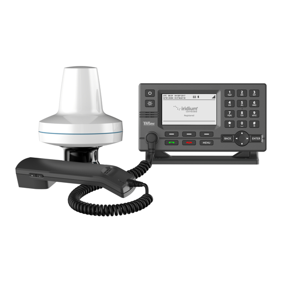
The LT-3100 Satellite Communications System is a standalone communication product, which is using the Iridium® satellite constellation. The LT-3100 system is working on the Iridium® legacy satellites as well as the new Iridium® NEXT satellites, which are taking over the Iridium services throughout 2018. An overview of the LT-3100 system is illustrated in Figure 1. -
Page 15: Installation And Mounting
LT-3100 User & Installation Manual Rev. 1.02 Installation and Mounting Installation and Mounting LT-3110 Control Unit The LT-3110 Control Unit is the master unit in the system, supporting all external interfaces and the operational user interface. The LT-3110 Control Unit is designed for indoor mounting. Check the specifications in App. - Page 16 (P/N: 91-100771) or Flush Mount, Control Unit (P/N: 91-100772) - illustrated in Figure 4 and Figure 5. The Flush Mount, Control Unit is not included in the LT-3100 Satellite Communications System – Basic (P/N: 90-101142) and must be ordered separately.
- Page 17 LT-3100 User & Installation Manual Rev. 1.02 Installation and Mounting The Bracket Mount and Flush Mount for the LT-3110 Control Unit are illustrated in Figure 4 and Figure 5. Figure 4: Bracket Mount, Control Unit. Figure 5: Flush Mount, Control Unit.
-
Page 18: Lt-3120 Handset
Installation and Mounting LT-3120 Handset The LT-3120 Handset is the primary voice interface for the LT-3100 system. The LT-3120 Handset must be connected on the front of the LT-3110 Control Unit. The connector is illustrated in Figure 2 on page 5. -
Page 19: Lt-3121 Cradle
LT-3100 User & Installation Manual Rev. 1.02 Installation and Mounting LT-3121 Cradle The LT-3121 Cradle is used together with the LT-3120 Handset. The LT-3121 Cradle should be mounted next to the LT-3110 Control Unit, supporting the LT-3120 Handset. The LT-3121 Cradle specifications are available in App. -
Page 20: Lt-3130 Antenna Unit
Mount the unit on a rigid structure with a minimum of exposure to vibration and shock • Mount the unit using either the Bracket Mount or Pole Mount provided by Lars Thrane A/S • Mount the unit outdoor with an ambient temperature between -25°C to +55°C (-13°F to +131°F) •... - Page 21 The safety distance from the LT-3130 Antenna Unit, is 0.1 m (0.3 ft), in order to comply with the regional regulations. IMPORTANT: Due to the adjacency of the Iridium and Inmarsat frequency bands, the LT-3100 Satellite Communications System may not co-operate in the proximity of active Inmarsat equipment.
- Page 22 LT-3100 User & Installation Manual Rev. 1.02 Installation and Mounting The LT-3130 Antenna Unit shall me mounted minimum 1 m from MF-HF, VHF, and UHF antennas. Figure 12: LT-3130 Antenna Unit – Separation to MF-HF, VHF, and UHF antennas. NOTE: The LT-3130 Antenna Unit must be installed with a 360°...
-
Page 23: Bracket Mount, Antenna Unit
LT-3100 User & Installation Manual Rev. 1.02 Installation and Mounting Bracket Mount, Antenna Unit The Bracket Mount (1.5” to 2.5” tube), Antenna Unit installation options are illustrated in Figure 14 to Figure 17. Figure 14: Bracket Mount (1.5” to 2.5” tube), Figure 15: Bracket Mount (1.5”... - Page 24 LT-3100 User & Installation Manual Rev. 1.02 Installation and Mounting Figure 16: Bracket Mount (1.5” to 2.5” tube), Antenna Unit – horizontal tube mount. The Bracket Mount (1.5” to 2.5” tube), Antenna Unit can support tubes in the interval 1.5” to 2.5”. The torques are specified in Figure 17.
-
Page 25: Pole Mount, Antenna Unit
LT-3100 User & Installation Manual Rev. 1.02 Installation and Mounting Pole Mount, Antenna Unit The Pole Mount (1.5” tube), Antenna Unit is illustrated in Figure 18 to Figure 20. Figure 18: Pole Mount (1.5” tube), Antenna Unit. Pole mount installation procedure: 1. - Page 26 LT-3100 User & Installation Manual Rev. 1.02 Installation and Mounting Figure 19: Pole Mount (1.5” tube), Figure 20: Pole Mount (1.5” tube), Antenna Unit. Antenna Unit. NOTE: The Pole Mount (1.5” tube), Antenna Unit only support a 1.5” tube. The pinot screws (antenna and pole lock) torques are specified in Figure 19 and Figure 20.
-
Page 27: Interfaces
LT-3130 Antenna Unit. DC input The LT-3100 system is designed to be used on 12 VDC and 24 VDC power buses (nominal). External DC power to the LT-3100 system is provided by connecting the proprietary 91-100767 power cable, 3m - delivered by Lars Thrane A/S. - Page 28 PUK codes The SIM card will be delivered with the SIM lock feature disabled. Thus, the LT-3100 system will be operational as soon as the SIM card is inserted. If the user decides to activate the SIM lock function from the UI display, then the PIN code is required next time the LT-3100 system is powered up.
-
Page 29: Ethernet (Rj45)
The auxiliary interface is not supported in software version 1.01. NOTE: Use only the 91-100768 Auxiliary Cable, 3m delivered by Lars Thrane A/S for connecting to the auxiliary connector on the backside of the LT-3110 Control Unit. The Auxiliary Cable, 3m is an accessory part and must be acquired separately. -
Page 30: Antenna
LT-3100 User & Installation Manual Rev. 1.02 Interfaces Antenna The LT-3110 Control Unit and the LT-3130 Antenna Unit must be connected using a coaxial cable. Both the control unit and the antenna unit has a N connector (female) mounted. This section will specify the requirements to the coaxial cable. - Page 31 Lars Thrane A/S has calculated the maximum allowed cable lengths with two coaxial cables as illustrated in Table 3. The two cables are FF195LSFROH (~RG-58) and FF400LSFROH (~RG-214).
-
Page 32: User Interface (Ui)
User Interface (UI) User Interface (UI) The LT-3100 system is controlled from the LT-3110 Control Unit, which is the interface for operating and configuring the system. The control unit has a 4.3” TFT-LCD display, supporting day and night modes. The layout of the display and buttons is illustrated in Figure 23. -
Page 33: Menu
Menu The LT-3100 system’s main menu is accessed by pressing the MENU button on the keypad. The user will be presented with a layout as illustrated in Figure 24. Figure 24: LT-3110 Control Unit - UI display (main menu). -
Page 34: System Information
Iridium® Network and be ready for use. The LT-3100 system will inform the user, if the system is not properly installed, or the system cannot register onto the Iridium® Network. Figure 25 is illustrating a LT- 3100 system, which is registered on the Iridium®... - Page 35 User Interface (UI) Additional user information is available in the system and represented as a system text or as an icon in the status bar. Table 7 is listing the system text and describing the status of the LT-3100 system. System Text...
- Page 36 User Interface (UI) The LT-3100 system can in addition to the system text also show an icon, which might be related to the status text, but not necessarily. The icon will be available in the icon line and might indicate a problem, but can also indicate a status of the system, or a service information to the user.
-
Page 37: Make A Voice Call
The LT-3100 system must be properly installed, connected, and configured before trying to establish a phone call. The LT-3100 system will inform the user about the status of the system, and whether the system is ready to initiate a call. - Page 38 User Interface (UI) Off-hook mode: In off-hook mode, the user starts to place the LT-3100 system into off-hook mode (ready tone available). The off-hook mode can be obtained in two ways: lifting the handset out of the cradle or pressing the green off-hook button, prior to typing any digits of the called number.
- Page 39 LT-3100 User & Installation Manual Rev. 1.02 User Interface (UI) The voice call connection can be described with the following states: • State 1: Type in number • State 2: “Connecting…” • State 3: “Duration: MM:SS” – (if call is successfully connected) where MM are minutes and SS are seconds.
-
Page 40: Web Server
LT-3100 User & Installation Manual Rev. 1.02 Web server Web server The LT-3110 Control Unit has a built-in webserver, which can be accessed from the Ethernet (RJ45) interface from the back side of the control unit. A PC must be connected to the control unit, either directly by connecting an Ethernet cable between a PC and the LT-3110 Control Unit, or by connecting the LT-3110 Control Unit to a Local Area Network (LAN), to where the PC is connected. -
Page 41: Dashboard
Lars Thrane A/S in case of required support and assistance. The diagnostic report contains technical data, from the LT-3100 system, and will help identify and resolve problems at the installation site. This is to avoid sending back the LT-3100 system for unnecessary debug and repair, at the Lars Thrane A/S facility. -
Page 42: Accessing The Built-In Web Server
5. Press ‘Details’ and you will be presented for an extended page view (including a link), which will direct you to the LT-3100 System dashboard ‘Go on to the webpage (Not recommended)’. 6. You will now see the LT-3100 system dashboard. -
Page 43: Service & Repair
If the LT-3100 system for some reason does not work as described in this manual, make contact with the distributor or dealer, from where the product was originally bought. The distributor or dealer will have experience and know-how to assist with further technical support and troubleshooting. -
Page 44: Appendixes
LT-3100 User & Installation Manual Rev. 1.02 Appendixes Appendixes App. A - Specifications LT-3100 Satellite Communications System Certification & standards Maritime CE, IC, FCC, RCM, RoHS, Iridium® Vibration, operational IEC 60945 (sine) & proprietary Maritime Random profile Vibration, survival Proprietary Maritime Random profile... -
Page 45: App. B - Outline Drawing: Lt-3110 Control Unit
LT-3100 User & Installation Manual Rev. 1.02 Appendixes App. B - Outline Drawing: LT-3110 Control Unit Figure 32: Outline Drawing: LT-3110 Control Unit Lars Thrane A/S www.thrane.eu Page 35 of 42... -
Page 46: App. C - Outline Drawing: Bracket Mount, Control Unit
LT-3100 User & Installation Manual Rev. 1.02 Appendixes App. C - Outline Drawing: Bracket Mount, Control Unit Figure 33: Outline Drawing: Bracket Mount, Control Unit Lars Thrane A/S www.thrane.eu Page 36 of 42... -
Page 47: App. D - Outline Drawing: Flush Mount, Control Unit
LT-3100 User & Installation Manual Rev. 1.02 Appendixes App. D - Outline Drawing: Flush Mount, Control Unit Figure 34: Outline Drawing: Flush Mount, Control Unit Lars Thrane A/S www.thrane.eu Page 37 of 42... -
Page 48: App. E - Outline Drawing: Lt-3130 Antenna Unit
LT-3100 User & Installation Manual Rev. 1.02 Appendixes App. E - Outline Drawing: LT-3130 Antenna Unit Figure 35: Outline Drawing: LT-3130 Antenna Unit Lars Thrane A/S www.thrane.eu Page 38 of 42... -
Page 49: App. F - Outline Drawing: Pole Mount, Antenna Unit
LT-3100 User & Installation Manual Rev. 1.02 Appendixes App. F - Outline Drawing: Pole Mount, Antenna Unit NOTE: The Pole Mount (1.5” tube), Antenna Unit interfaces to a tube of maximum 1.5” (38.1 mm), measured outer diameter. The total weight of the Pole Mount is 190 g (0.42 lbs). -
Page 50: App. G - Outline Drawing: Bracket Mount, Antenna Unit
LT-3100 User & Installation Manual Rev. 1.02 Appendixes App. G - Outline Drawing: Bracket Mount, Antenna Unit NOTE: The Bracket Mount (1.5” to 2.5” tube), Antenna Unit interfaces to a tube of maximum 2.5” (63.5 mm), measured outer diameter. The total weight of the Bracket Mount is 714 g (1.57 lbs). -
Page 51: App. H - Outline Drawing: Lt-3120 Handset
LT-3100 User & Installation Manual Rev. 1.02 Appendixes App. H - Outline Drawing: LT-3120 Handset Figure 38: Outline Drawing: LT-3120 Handset Lars Thrane A/S www.thrane.eu Page 41 of 42... -
Page 52: App. I - Outline Drawing: Lt-3121 Cradle
LT-3100 User & Installation Manual Rev. 1.02 Appendixes App. I - Outline Drawing: LT-3121 Cradle Figure 39: Outline Drawing: LT-3121 Cradle Lars Thrane A/S www.thrane.eu Page 42 of 42... - Page 54 Lars Thrane A/S Skovlytoften 33 2840 Holte Denmark www.thrane.eu...