Advertisement
Quick Links
g
Introduction
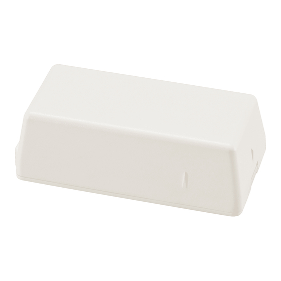
These are the GE 319.5 Crystal Maxlife Door/Window Sensor
Installation Instructions for models 60-362N-10-319.5 and 60-
362N-11-319.5. Install the sensor (Figure 1) on doors, windows,
and other objects that open and close. The sensor transmits signals
to the control panel when a magnet mounted near the sensor is
moved away from or closer to the sensor. The sensor is equipped
with a cover tamper microswitch for additional security.
Figure 1. Sensor
Use the following installation guidelines:
• Mount the sensor on the door frame and the magnet on the
door. For double doors, mount the sensor on the least-used
door and the magnet on the most-used door.
• Where possible, install sensors within 100 ft. (30 m) of the
panel. While a transmitter may have an open-air range of
500 ft. (150 m) or more, the environment at the installation
site may have a significant affect on operational range.
Changing a sensor location may improve wireless commu-
nication.
• Line up the alignment mark on the magnet to one of the
alignment marks on the sensor.
• Mount sensors at least 4.7 in. (12 cm) above the floor to
avoid potential damage.
• Avoid mounting sensors in areas where they will be exposed
to moisture or where the operating temperature range will
exceed the operating range.
• If possible, mount directly to a stud. If a stud is not avail-
able, use plastic anchors.
• Avoid mounting the sensor in areas with a large quantity of
metal or electrical wiring.
• Only one input can be used at any given time.
• You must mount the magnet within 3/8 in. (0.95 cm) of the
sensor.
• Mount sensors with screws, not double-sided tape.
• Only install the EOL resistor when an external contact is
used.
You will need the following tools and materials:
• Two #6 x 1.00 in. PPH (Phillips panhead) screws and two
plastic anchors for mounting the sensor (included).
• Two #6 x 0.625 in. PPH screws for mounting the magnet
(included).
319.5 Crystal Maxlife Door/Window Sensor
Installation Instructions
• External contact 4.7 kohm end-of-line (EOL) resistor
(included).
• Phillips screwdriver
CAUTION: You must be free of all static electricity
when handling electronic components. Touch a
grounded, bare metal surface before touching a
circuit board or wear a grounded wrist strap.
Programming
This section describes general guidelines for programming
(learning) the sensor into panel memory. Refer to the specific
panel or receiver documentation for complete programming
details.
To program the sensor:
1.
Remove the sensor cover by squeezing the cover ends
firmly releasing the tab (Figure 2) from sensor base slot.
Figure 2. Sensor tab
2.
If required, insert the battery into the battery holder,
observing correct polarity (Figure 3).
Figure 3. Board components
Terminals
Battery
holder
3.
Set the panel to program mode.
4.
Proceed to the Learn sensors menu.
5.
Set the external contact in the alarm condition (see
contact wiring
6.
Press and release the tamper switch (Figure 3) on the sensor
until the panel responds.
7.
Select the appropriate sensor group and number.
8.
Exit program mode.
466-2298B • January 2009
Copyright © 2009 GE Security
Tamper switch
Positive
Reed B
on page 3).
Tab
Reed A
Input
jumper
External
Advertisement

Related Manuals for GE 319.5


Summary of Contents for GE 319.5
-
Page 1: Installation Instructions
Copyright © 2009 GE Security Introduction • External contact 4.7 kohm end-of-line (EOL) resistor (included). These are the GE 319.5 Crystal Maxlife Door/Window Sensor • Phillips screwdriver Installation Instructions for models 60-362N-10-319.5 and 60- 362N-11-319.5. Install the sensor (Figure 1) on doors, windows, and other objects that open and close. - Page 2 319.5 Crystal Maxlife Door/Window Sensor Installation Instructions Input selection Mounting Only one door/window input can be used at any given time. For To mount the sensor: example, if the external contact is used, internal reed switches Remove the sensor battery.
-
Page 3: Battery Replacement
Brown: 60-362N-11-319.5 White: 60-362N-10-319.5 Frequency 319.5 MHz CAUTION: You must install the EOL resistor at the Compatibility GE Security 319.5 MHz control panels/ external detection device for proper supervision. receivers Battery type 3.0 V, 1300 mAh lithium Required batteries Duracell DL 123A, Panasonic CR123A, Sanyo...