NETGEAR GS752TP Software Administration Manual
Gigabit smart switches
Hide thumbs
Also See for GS752TP:
- Hardware installation manual (36 pages) ,
- Installation manual (2 pages)

Related Manuals for NETGEAR GS752TP


Summary of Contents for NETGEAR GS752TP
- Page 1 GS752TP, GS728TP, and GS728TPP Gigabit Smart Switches Soft ware Admi nist rat ion M anual December 2013 202-11137-04 350 East Plumeria Drive San Jose, CA 95134...
- Page 2 Trademarks NETGEAR, the NETGEAR logo, and Connect with Innovation are trademarks and/or registered trademarks of NETGEAR, Inc. and/or its subsidiaries in the United States and/or other countries. Information is subject to change without notice. © NETGEAR, Inc. All rights reserved.
-
Page 3: Table Of Contents
Chapter 1 Getting Started Getting Started with the NETGEAR Switch....... . 9 Switch Management Interface . - Page 4 GS752TP, GS728TP, and GS728TPP Gigabit Smart Switches DHCP Snooping Interface Configuration......69 DHCP Snooping Binding Configuration .
- Page 5 GS752TP, GS728TP, and GS728TPP Gigabit Smart Switches Configure VLAN Routing ......... . 130 Configure and View Routes .
- Page 6 GS752TP, GS728TP, and GS728TPP Gigabit Smart Switches MAC ACL ............191 MAC Rules .
- Page 7 GS752TP, GS728TP, and GS728TPP Gigabit Smart Switches Online Help ............244 Support.
-
Page 8: Chapter 1 Getting Started
Getting Started This manual describes how to configure and operate the GS752TP, GS728TP, and GS728TPP Gigabit Smart Switches by using the web-based graphical user interface (GUI). This manual describes the software configuration procedures and explains the options available within those... -
Page 9: Getting Started With The Netgear Switch
GS752TP, GS728TP, and GS728TPP Gigabit Smart Switches Getting Started with the NETGEAR Switch This chapter provides an overview of starting your NETGEAR switch and accessing the user interface. It also describes some actions that can be performed in the Smart Control Center (SCC) application, which can be downloaded to your computer. -
Page 10: Switch Management Interface
You can configure all switch features, such as VLANs, QoS, and ACLs, by using the web-based management interface. NETGEAR provides the Smart Control Center utility with this product. This program runs under Windows XP, Windows 2003, Windows 2008 or Windows 7 (32 bit and 64 bit) and provides a front end that discovers the switches on your network segment (L2 broadcast domain). -
Page 11: Connect The Switch To The Network
GS752TP, GS728TP, and GS728TPP Gigabit Smart Switches Connect the Switch to the Network To enable remote management of the switch through a web browser or SNMP, you must connect the switch to the network and configure it with network information (an IP address, subnet mask, and default gateway). -
Page 12: Discover A Switch In A Network With A Dhcp Server
GS752TP, GS728TP, and GS728TPP Gigabit Smart Switches Discover a Switch in a Network with a DHCP Server This section describes how to set up your switch in a network that has a DHCP server. The DHCP client on the switch is enabled by default. When you connect it to your network, the DHCP server automatically assigns an IP address to your switch. - Page 13 GS752TP, GS728TP, and GS728TPP Gigabit Smart Switches Select your switch by clicking the line that displays the switch, then click the Web Browser Access button. The Smart Control Center displays a login window. The default password is password. Use this screen to manage your switch. For more...
-
Page 14: Switch Discovery In A Network Without A Dhcp Server
Install the Smart Control Center on your computer. Start the Smart Control Center. Click Discover for the Smart Control Center to find your NETGEAR switch. The utility broadcasts Layer 2 discovery packets within the broadcast domain to discover the switch. -
Page 15: Configure The Network Settings On The Administrative System
GS752TP, GS728TP, and GS728TPP Gigabit Smart Switches Select the Disabled radio button to disable DHCP. Enter the static switch IP address, gateway IP address, and subnet mask for the switch and type your password. Tip: You must enter the current password every time you use the Smart Control Center to update the switch setting. - Page 16 GS752TP, GS728TP, and GS728TPP Gigabit Smart Switches WARNING: When you change the IP address of your administrative system, connection to the rest of the network is lost. Be sure to write down your current network address settings before you change them.
-
Page 17: Access The Management Interface From The Web
Open a web browser and enter the IP address of the switch in the address field. You must be able to ping the IP address of the NETGEAR switch management interface from your administrative system for web access to be available. If you used the Smart Control Center to set up the IP address and subnet mask, either with or without a DHCP server, use that IP address in the address field of your web browser. - Page 18 GS752TP, GS728TP, and GS728TPP Gigabit Smart Switches Logout button Help link Navigation tab Configuration menus Help screen Configuration status and options Screen menu Figure 1. Configuration Status and Options Navigation Tabs, Configuration Menus, and Screen Menu The navigation tabs along the top of the web interface give you quick access to the various switch functions.
- Page 19 GS752TP, GS728TP, and GS728TPP Gigabit Smart Switches Some items in the menu expand to reveal multiple submenu links, as shown in the following: Link Submenu Links When you click a menu item that includes multiple configuration screens, the item becomes preceded by a down arrow symbol and expands to display the additional submenu links.
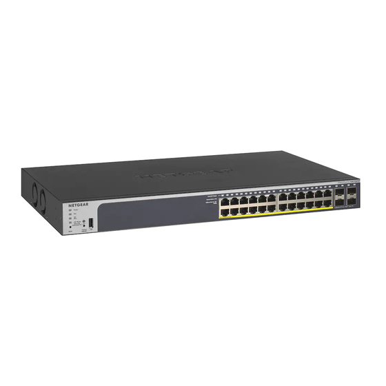
- Page 20 A solid green LED indicates that the Port LED is in Ethernet Mode. • A solid yellow LED indicates that the Port LED is in PoE Mode. The following image shows the device view of the NETGEAR switch. Getting Started...
- Page 21 GS752TP, GS728TP, and GS728TPP Gigabit Smart Switches Figure 2. Ports and LEDs on the Switching Devices Click the port you want to view or configure to see a menu that displays statistics and configuration options. Click the menu option to access the screen that contains the configuration or monitoring options.
-
Page 22: Use Snmp
GS752TP, GS728TP, and GS728TPP Gigabit Smart Switches Help Screen Access Every screen contains a link to the online help , which contains information to help configure and manage the switch. The online help screens are context-sensitive. For example, if the IP Addressing screen is open, the help topic for that screen displays if you click Help. - Page 23 GS752TP, GS728TP, and GS728TPP Gigabit Smart Switches Click APPLY. To access configuration information for SNMPv1 or SNMPv2: Select System SNMP SNMPv1/v2 Follow the link to the screen that contains the information to configure. SNMP on page 50 for more information...
-
Page 24: Interface Naming Convention
The switches support the following ports: • GS752TP. Ports 1–48 are 10/100/1000M AutoSensing Gigabit ports, and ports 49–52 are 100/1000M SFP ports. The first 8 ports are PoE+ providing 30W of DC power, and the remaining copper ports are PoE (Power over Environment) providing 15.4W of DC power. -
Page 25: Chapter 2 Configuring System Information
Configuring System Information Use the features in the System tab to define the switch’s relationship to its environment. The System tab contains links to screens described in the following sections: • Management • • SNMP • LLDP • Services—DHCP Snooping... -
Page 26: Management
GS752TP, GS728TP, and GS728TPP Gigabit Smart Switches Management This section describes how to display the switch status and specify some basic switch information, such as the management interface IP address, system clock settings, and DNS information. From the Management menu, you can access screens described in the following sections: •... -
Page 27: Ip Configuration
GS752TP, GS728TP, and GS728TPP Gigabit Smart Switches • System Location. Enter the location of this switch. You can use up to 160 alphanumeric characters. The factory default is blank. • System Contact. Enter the contact person for this switch. You can use up to 160 alphanumeric characters. - Page 28 GS752TP, GS728TP, and GS728TPP Gigabit Smart Switches The following screen displays: Select the appropriate radio button to determine how to configure the network information for the switch management interface: • Dynamic IP Address (DHCP). Specifies that the switch must obtain the IP address through a DHCP server.
-
Page 29: Ipv6 Network Configuration
GS752TP, GS728TP, and GS728TPP Gigabit Smart Switches Note: Make sure that the PVID of at least one port that is a port of the VLAN is the same as the management VLAN ID. For information about creating VLANs and configuring the PVID for a port, see VLANs page 82. - Page 30 GS752TP, GS728TP, and GS728TPP Gigabit Smart Switches The following screen displays: In the Global Configuration Section, configure the following: • Admin Mode. Enable or disable the IPv6 network interface on the switch. The default value is Enable. • IPv6 Address Auto Configuration Mode. The IPv6 address for the IPv6 network interface is automatically configured if this option is enabled.
-
Page 31: Ipv6 Network Neighbors
GS752TP, GS728TP, and GS728TPP Gigabit Smart Switches IPv6 Network Neighbors To view the IPv6 Network Interface Neighbors: Select System Management IPv6 Network Neighbors. The following screen displays: Properties of each neighbor are displayed, as described below: •... -
Page 32: Time
GS752TP, GS728TP, and GS728TPP Gigabit Smart Switches Time The switch software supports the Simple Network Time Protocol (SNTP). You can also set the system time manually SNTP assures accurate network device clock time synchronization up to the millisecond. Time synchronization is performed by a network SNTP server. The software operates only as an SNTP client and cannot provide time services to other systems. - Page 33 GS752TP, GS728TP, and GS728TPP Gigabit Smart Switches The following screen displays: Next to the Clock Source, select Local. In the Date field, enter the date in the DD/MM/YYYY format. In the Time field, enter the time in HH:MM:SS format. Note: If you do not enter a date and time, the switch calculates the date and time using the CPU’s clock cycle.
-
Page 34: Sntp Server Configuration
GS752TP, GS728TP, and GS728TPP Gigabit Smart Switches Table 5. SNTP Global Status fields. Field Description Version Specifies the SNTP version the client supports. Supported Mode Specifies the SNTP modes the client supports. Multiple modes might be supported by a client. - Page 35 GS752TP, GS728TP, and GS728TPP Gigabit Smart Switches The following screen displays: Enter the appropriate SNTP server information in the following fields: • Server Type. Specifies whether the address for the SNTP server is an IP address (IPv4) or host name (DNS).
-
Page 36: Dns
GS752TP, GS728TP, and GS728TPP Gigabit Smart Switches Table 6. SNTP Server Status Table Fields Field Description Address Specifies all the existing server addresses. If no server configuration exists, a message saying “No SNTP server exists” flashes on the screen. Last Update Time Specifies the local date and time (UTC) of the server response, according to which the system clock was updated. -
Page 37: Host Configuration
GS752TP, GS728TP, and GS728TPP Gigabit Smart Switches domain name. For example, if the default domain name is netgear.com and the host name to resolve is test, test.netgear.com is used in DNS resolution queries. in the DNS Server field, enter an IP address representing the DNS server to which the switch sends DNS queries, and click ADD. -
Page 38: Green Ethernet Configuration
GS752TP, GS728TP, and GS728TPP Gigabit Smart Switches Table 7. Dynamic Host Configuration table fields Field Description Host Lists the host name you assign to the specified IP address. Type The type of the dynamic entry. IPv4/IPv6 Address Lists the IP address associated with the host name. - Page 39 GS752TP, GS728TP, and GS728TPP Gigabit Smart Switches The following screen displays: Enable or disable the Auto Power Down Mode. • Enable. When the port link is down, the PHY automatically goes down for a short period and then wakes up to check link pulses. This allows the port to continue to perform autonegotiation while consuming less power when no link partner is present.
- Page 40 GS752TP, GS728TP, and GS728TPP Gigabit Smart Switches The following screen displays: Select the following interface settings for the physical port: • Go To Interface. Enter a port identifier (appears in the Port column) and click the Go button. The table entry corresponding to the specified port is selected.
- Page 41 GS752TP, GS728TP, and GS728TPP Gigabit Smart Switches The following screen displays: View or configure the Local Device Information: • Interface. The interface to be displayed or configured. • Energy Detect Admin Mode. Select Enable or Disable. • Operational Status. Displays the Energy Detect operational status, either Active or Inactive.
- Page 42 GS752TP, GS728TP, and GS728TPP Gigabit Smart Switches • Remote Tw_sys_tx (uSec). Displays the amount of time the Remote Tw_sys_tx has been present on the port. • Remote Tw_sys_tx Echo (uSec). Displays the amount of time the Remote Tw_sys_tx Echo has been present on the port.
- Page 43 GS752TP, GS728TP, and GS728TPP Gigabit Smart Switches • EEE Admin Mode. Displays the EEE Admin mode for each of the local interfaces (Enable or Disable). Configuring System Information...
-
Page 44: Poe
RPS4000. • GS752TP. Ports 1–8 support both IEEE802.3 at and af, and ports 9–48 support IEEE802.3af. The maximum power budget is 384 Watts. The power limit of a port is set to the minimum between the class and the configured max power limit. - Page 45 GS752TP, GS728TP, and GS728TPP Gigabit Smart Switches The PoE Configuration screen displays the fields described below: Table 8. PoE Configuration Information Field Description Power Status Indicates whether the PoE capability is on or off. Nominal Power Indicates the maximum amount of power the switch can provide to all ports.
-
Page 46: Poe Port Configuration
GS752TP, GS728TP, and GS728TPP Gigabit Smart Switches PoE Port Configuration Use the PoE Port Configuration screen to configure PoE settings on the ports. The following information is displayed for each port: Table 9. PSE Port Information Field Description Admin Mode Indicates whether the port can deliver power (Enable) or cannot deliver power (Disable). -
Page 47: Timer Global Configuration
GS752TP, GS728TP, and GS728TPP Gigabit Smart Switches The following screen displays: Select the check box next to one or more of the ports. Configure the settings in the top row for the selected ports: • Admin Mode. Select whether to enable or disable the ability of the port to deliver power. - Page 48 GS752TP, GS728TP, and GS728TPP Gigabit Smart Switches The following screen displays: b. Enter the name of the timer in the Timer Schedule Name field. c. Click ADD. Configure the timer: a. Select System > PoE > Advanced > Timer Schedule Configuration.
- Page 49 GS752TP, GS728TP, and GS728TPP Gigabit Smart Switches b. From the Timer Schedule Name list, select one of the timers defined the previous step. c. Enter the time of day to turn off power in the Shutdown Time Start field. The time range is from 00:00 to 23:59.
-
Page 50: Snmp
GS752TP, GS728TP, and GS728TPP Gigabit Smart Switches SNMP From SNMP menu under the System tab, you can configure SNMP settings for SNMP v1/v2 and SNMPv3. SNMP features are described in the following sections: • SNMP v1/v2 • Trap Flags •... - Page 51 GS752TP, GS728TP, and GS728TPP Gigabit Smart Switches The following screen displays: To add a new SNMP community, enter community information in the available fields described below. • Management Station IP. Specify the IP address of the management station. Together, the management station IP and the management station IP mask denote a range of IP addresses from which SNMP clients can use that community to access this device.
-
Page 52: Trap Configuration
GS752TP, GS728TP, and GS728TPP Gigabit Smart Switches Trap Configuration This screen displays an entry for every active Trap Receiver. To configure SNMP trap settings: Select System SNMP SNMP v1/v2 Trap Configuration. The following screen displays: To add a host that receives SNMP traps: ... -
Page 53: Trap Flags
GS752TP, GS728TP, and GS728TPP Gigabit Smart Switches Trap Flags Use the Trap Flags screen to enable or disable traps the switch can send to an SNMP manager. When the condition identified by an active trap encounters the switch, a trap message is sent to any enabled SNMP trap receivers, and a message is written to the trap log. -
Page 54: Snmp V3 User Configuration
GS752TP, GS728TP, and GS728TPP Gigabit Smart Switches To access the Supported MIBS screen, select System SNMP SNMP v1/v2 Supported MIBS. SNMP v3 User Configuration This is the configuration for SNMP v3. The SNMPv3 Access Mode is a read-only field that shows the access privileges for the user account. - Page 55 GS752TP, GS728TP, and GS728TPP Gigabit Smart Switches The following screen displays: Next to Authentication Protocol, select the SNMPv3 Authentication Protocol setting for the selected user account. The valid authentication protocols are None, MD5, or SHA. • None. The user is unable to access the SNMP data from an SNMP browser.
-
Page 56: Lldp
GS752TP, GS728TP, and GS728TPP Gigabit Smart Switches LLDP The IEEE 802.1AB-defined standard, Link Layer Discovery Protocol (LLDP), allows stations on an 802 LAN to advertise major capabilities and physical descriptions. A network manager views this information to identify system topology and detect bad configurations on the LAN. - Page 57 GS752TP, GS728TP, and GS728TPP Gigabit Smart Switches The following screen displays: Note: You can also access the LLDP Configuration screen by selecting System > LLDP > Advanced > LLDP Configuration. Configure the following LLDP settings: • TLV Advertised Interval. Specify the interval at which frames are transmitted. The default is 30 seconds, and the valid range is 5–32768 seconds.
-
Page 58: Lldp Port Settings
GS752TP, GS728TP, and GS728TPP Gigabit Smart Switches LLDP Port Settings Use the LLDP Port Settings screen to specify LLDP parameters that are applied to a specific interface. To configure LLDP port settings: Select System LLDP Advanced LLDP Port Settings. -
Page 59: Lldp-Med Network Policy
GS752TP, GS728TP, and GS728TPP Gigabit Smart Switches • Optional TLVs. Enable or disable the transmission of optional type-length value (TLV) information from the interface. The TLV information includes the system name, system description, system capabilities, and port description. For information about... -
Page 60: Lldp-Med Port Settings
GS752TP, GS728TP, and GS728TPP Gigabit Smart Switches • User Priority. The priority associated with the policy. • DSCP. The DSCP associated with a particular policy type. LLDP-MED Port Settings Use this screen to enable LLDP-MED mode on an interface and configure its properties. -
Page 61: Local Information
GS752TP, GS728TP, and GS728TPP Gigabit Smart Switches • Inventory Click APPLY to apply the new settings to the system. Configuration changes take effect immediately. Local Information Use the LLDP Local Information screen to view the data that each port advertises through LLDP. - Page 62 GS752TP, GS728TP, and GS728TPP Gigabit Smart Switches The following screen displays information for the selected port: The following table describes the detailed local information that displays for the selected port: Table 10. Detailed local information. Field Description Managed Address Address SubType Displays the type of address the management interface uses, such as an IPv4 address.
-
Page 63: Neighbors Information
GS752TP, GS728TP, and GS728TPP Gigabit Smart Switches Field Description Operational MAU Type Displays the Medium Attachment Unit (MAU) type. The MAU performs physical layer functions, including digital data conversion from the Ethernet interface collision detection and bit injection into the network. - Page 64 GS752TP, GS728TP, and GS728TPP Gigabit Smart Switches The following screen displays: The following table describes the information that displays for all LLDP neighbors that have been discovered: Table 11. LLDP neighbors information. Field Description MSAP Entry Displays the Media Service Access Point (MSAP) entry number for the remote device.
- Page 65 GS752TP, GS728TP, and GS728TPP Gigabit Smart Switches The following screen displays information for the selected port: The following table describes the information that displays for a selected port: Table 12. Port Details Field Description Port Details Local Port Displays the interface on the local system that received LLDP information from a remote system.
- Page 66 GS752TP, GS728TP, and GS728TPP Gigabit Smart Switches Field Description System Capabilities Specifies the system capabilities of the remote system. Managed Addresses Address SubType Specifies the type of the management address. Address Specifies the advertised management address of the remote system.
- Page 67 GS752TP, GS728TP, and GS728TPP Gigabit Smart Switches Field Description Civic The physical location, such as the street address, the remote device has advertised in the location TLV, for example, 123 45th St. E. The field value length range is 6–160 characters.
-
Page 68: Services-Dhcp Snooping
GS752TP, GS728TP, and GS728TPP Gigabit Smart Switches Services—DHCP Snooping DHCP snooping is a useful feature that provides security by filtering untrusted DHCP messages and by building and maintaining a DHCP snooping binding table. An untrusted message is a message that is received from outside the network or firewall and that can cause traffic attacks within your network. -
Page 69: Dhcp Snooping Interface Configuration
GS752TP, GS728TP, and GS728TPP Gigabit Smart Switches The following screen displays: Next to DHCP Snooping Mode, select Enable or Disable to turn the DHCP snooping feature on or off. The factory default is disabled. Next to MAC Address Validation, select Enable or Disable to turn on or off the MAC address validation feature. -
Page 70: Dhcp Snooping Binding Configuration
GS752TP, GS728TP, and GS728TPP Gigabit Smart Switches The following screen displays: In the Go To Interface field, enter the interface name and click the Go button. The entry corresponding to the specified interface is selected. To configure DHCP snooping interface settings, click PORTS, LAGS, or All. - Page 71 GS752TP, GS728TP, and GS728TPP Gigabit Smart Switches The following screen displays: In the Static Binding Configuration section, in the Interface list, select the interface for which to add a binding to the DHCP snooping database. In the MAC Address field, specify the MAC address for the binding to be added.
-
Page 72: Dhcp Snooping Persistent Configuration
GS752TP, GS728TP, and GS728TPP Gigabit Smart Switches Field Description VLAN ID The VLAN for the binding entry in the binding database. The valid range of the VLAN ID is 1–4093. IP Address The IP address for the binding entry in the binding database. -
Page 73: Chapter 3 Configuring Switching Information
Configuring Switching Information Use the features you access from the Switching tab to define Layer 2 features. The Switching tab contains links to features described in the following sections: • Ports • Link Aggregation Groups • VLANs • Voice VLAN •... -
Page 74: Ports
GS752TP, GS728TP, and GS728TPP Gigabit Smart Switches Ports The screens you access from the Ports menu allow you to view and monitor the physical port information for the ports available on the switch. From the Ports menu, you can access the features described in the following sections: •... -
Page 75: Port Configuration
GS752TP, GS728TP, and GS728TPP Gigabit Smart Switches • Enable. The switch sends pause packets if the port buffers become full. • Disable. The switch does not send pause packets if the port buffers become full. View the Jumbo Frames Status. - Page 76 GS752TP, GS728TP, and GS728TPP Gigabit Smart Switches Configure or view the settings: • Description. Enter the description string to be attached to a port. The string can be up to 64 characters in length. • Port Type. This field is blank for most ports. Otherwise, the possible values are: •...
-
Page 77: Link Aggregation Groups
GS752TP, GS728TP, and GS728TPP Gigabit Smart Switches Link Aggregation Groups Link aggregation groups (LAGs), which are also known as port channels, allow you to combine multiple full-duplex Ethernet links into a single logical link. Network devices treat the aggregation as if it were a single link, which increases fault tolerance and provides load sharing. - Page 78 GS752TP, GS728TP, and GS728TPP Gigabit Smart Switches The following screen displays: Select the check box next to the LAG to configure. You can select multiple LAGs to apply the same settings to the selected interfaces. Select the check box in the heading row to apply the same settings to all interfaces.
-
Page 79: Lag Membership
GS752TP, GS728TP, and GS728TPP Gigabit Smart Switches LAG Membership Use the LAG Membership screen to select two or more full-duplex Ethernet links to aggregate together to form a link aggregation group (LAG), which is also known as a port-channel. The switch can treat the port channel as if it were a single link. -
Page 80: Lacp Configuration
GS752TP, GS728TP, and GS728TPP Gigabit Smart Switches To view the ports that are members of the selected LAG, click the CURRENT MEMBERS button. LACP Configuration To configure LACP: Select Switching Advanced LACP Configuration. The following screen displays: In the LACP System Priority field, specify the device’s link aggregation priority relative to the... - Page 81 GS752TP, GS728TP, and GS728TPP Gigabit Smart Switches The following screen displays: Select the check box next to the port to configure. You can select multiple ports to apply the same settings to all selected ports. Note: You cannot select ports that are not participating in a LAG.
-
Page 82: Vlans
GS752TP, GS728TP, and GS728TPP Gigabit Smart Switches VLANs Adding virtual LAN (VLAN) support to a Layer 2 switch offers some of the benefits of both bridging and routing. Like a bridge, a VLAN switch forwards traffic based on the Layer 2 header, which is fast. - Page 83 GS752TP, GS728TP, and GS728TPP Gigabit Smart Switches The following screen displays: To add a VLAN, configure the VLAN ID, name, and type, and click ADD. You have the following options: • VLAN ID. Specify the VLAN identifier for the new VLAN. You can enter data in this field only when you are creating a VLAN.
-
Page 84: Vlan Membership Configuration
GS752TP, GS728TP, and GS728TPP Gigabit Smart Switches VLAN Membership Configuration Use this screen to configure VLAN port membership for a particular VLAN. You can select the Group Operation through this screen. To configure VLAN membership: Select Switching VLAN Advanced VLAN Membership. -
Page 85: Port Vlan Id Configuration
GS752TP, GS728TP, and GS728TPP Gigabit Smart Switches In the following screen, ports 6, 7, and 8 are being added as tagged members to VLAN 2. From the Group Operations list, select an identical configuration for all the ports. The possible values are: •... - Page 86 GS752TP, GS728TP, and GS728TPP Gigabit Smart Switches The following screen displays: Select the check box next to the interfaces to configure. You can select multiple interfaces to apply the same setting to the selected interfaces. Select the check box in the heading row to apply the same settings to all interfaces.
-
Page 87: Voice Vlan
GS752TP, GS728TP, and GS728TPP Gigabit Smart Switches In the Port Priority field, specify the default 802.1p priority assigned to untagged packets arriving at the port. Possible values are 0–7. Click APPLY to send the updated configuration to the switch. Configuration changes take effect immediately. -
Page 88: Voice Vlan Port Setting
GS752TP, GS728TP, and GS728TPP Gigabit Smart Switches The following screen displays: Next to Voice VLAN Status, enable or disable (default) voice VLAN on the switch. If the switch does not handle traffic from IP phones, the status must be disabled. -
Page 89: Voice Vlan Oui
GS752TP, GS728TP, and GS728TPP Gigabit Smart Switches The following screen displays: Select the check box next to the port to configure. You can select multiple check boxes to apply the same setting to all selected ports. Go To Interface. Enter the port to be configured and click the GO button. - Page 90 GS752TP, GS728TP, and GS728TPP Gigabit Smart Switches • 00:E0:75. VERILINK • 00:E0:BB. 3COM • 00:04:0D. AVAYA1 • 00:1B:4F. AVAYA2 You can select an existing OUI or add a new OUI and description to identify the IP phones on the network.
-
Page 91: Auto-Voip Configuration
GS752TP, GS728TP, and GS728TPP Gigabit Smart Switches Auto-VoIP Configuration Auto-VoIP automatically makes sure that time-sensitive voice traffic is given priority over data traffic on ports that have this feature enabled. Auto-VoIP checks for packets carrying the following VoIP protocols: •... -
Page 92: Spanning Tree Protocol
GS752TP, GS728TP, and GS728TPP Gigabit Smart Switches To configure Auto-VoIP interface settings for a physical port or a LAG port, click PORT, LAGS, or ALL. Enter the interface name in the Go To Interface field and click the Go button. -
Page 93: Stp Configuration
GS752TP, GS728TP, and GS728TPP Gigabit Smart Switches STP Configuration The STP Switch Configuration screen contains fields for enabling STP on the switch. To configure STP settings on the switch: Select Switching Basic STP Configuration. The following screen displays: Next to Spanning Tree State, specify whether to enable or disable spanning tree operation on the switch. -
Page 94: Cst Configuration
GS752TP, GS728TP, and GS728TPP Gigabit Smart Switches The Forward BPDU while STP Disabled field specifies whether spanning tree BPDUs should be forwarded or not while spanning-tree is disabled on the switch. Click APPLY to send the updated configuration to the switch. - Page 95 GS752TP, GS728TP, and GS728TPP Gigabit Smart Switches Specify values for CST in the following fields: • Bridge Priority. Specify the bridge priority value for the Common and Internal Spanning Tree (CST). When switches or bridges are running STP, each is assigned a priority.
-
Page 96: Cst Port Configuration
GS752TP, GS728TP, and GS728TPP Gigabit Smart Switches Table 15. MSTP Status Information. Field Description MST ID Table consisting of the MST instances (including the CST) and the corresponding VLAN IDs associated with each of them. Table consisting of the VLAN IDs and the corresponding FID associated with each of them. -
Page 97: Cst Port Status
GS752TP, GS728TP, and GS728TPP Gigabit Smart Switches • STP Status. Enable or disable the Spanning Tree Protocol administrative mode associated with the port or port channel. • Fast Link. Specifies if the specified port is an edge port with the CST. Possible values are Auto, Enable, or Disable. - Page 98 GS752TP, GS728TP, and GS728TPP Gigabit Smart Switches To display the CST Port Status screen, select Switching Advanced CST Port Status. The following screen displays: To view CST settings for an interface, click PORTS, LAGS, or All. The following table describes the CST Status information displayed on the screen.
-
Page 99: Rapid Stp
GS752TP, GS728TP, and GS728TPP Gigabit Smart Switches Field Description CST Regional Root Displays the bridge priority and base MAC address of the CST regional root. CST Path Cost Displays the path cost to the CST tree regional root. Port Forwarding State Displays the forwarding state of this port. -
Page 100: Mst Configuration
GS752TP, GS728TP, and GS728TPP Gigabit Smart Switches Field Description Fast Link Indicates whether the port is enabled as an edge port. Status The forwarding state of this port. MST Configuration Use the MST Configuration screen to configure Multiple Spanning Tree (MST) on the switch. -
Page 101: Mst Port Configuration
GS752TP, GS728TP, and GS728TPP Gigabit Smart Switches Configuration changes take place immediately. To modify an MST instance: Select the check box next to the instance to configure and update the values. You can select multiple check boxes to apply the same setting to all selected MTS instances. - Page 102 GS752TP, GS728TP, and GS728TPP Gigabit Smart Switches The following screen displays: Note: If no MST instances have been configured on the switch, the screen displays a “No MSTs Available” message. To view CST settings for an interface, click PORTS, LAGS, or All.
- Page 103 GS752TP, GS728TP, and GS728TPP Gigabit Smart Switches Table 19. MST port configuration information. Field Description Auto-calculated Port Path Displays that the path cost is not automatically calculated (Disabled). Path Cost cost is recalculated based on the link speed of the port if the configured value for Port Path Cost is 0.
-
Page 104: Multicast
GS752TP, GS728TP, and GS728TPP Gigabit Smart Switches Multicast Multicast IP traffic is traffic that is destined to a host group. The class D addresses identify the host groups for IPv4 multicast, which range from 224.0.0.0 to 239.255.255.255. The prefix ff00::/8 identifies the host groups for IPv6 multicast. - Page 105 GS752TP, GS728TP, and GS728TPP Gigabit Smart Switches The following screen displays: In the Search by MAC Address field, enter the MAC address whose MFDB table entry you want to display. Enter six 2-digit hexadecimal numbers separated by colons. For example, 01:01:23:43:45:67.
-
Page 106: Auto-Video Configuration
GS752TP, GS728TP, and GS728TPP Gigabit Smart Switches MFDB Statistics To access the MFDB Statistics screen, click Switching Multicast MFDB MFDB Statistics. The following screen displays: The MFDB Statistics screen displays the following: • Max MFDB Table Entries. The maximum number of entries that the MFDB table can hold. -
Page 107: Igmp Snooping
GS752TP, GS728TP, and GS728TPP Gigabit Smart Switches The following screen displays: Globally enable or disable the Auto-Video administrative mode for the switch by selecting Enable or Disable next to the Auto-Video Status radio button. The Auto-Video VLAN field shows the number of auto-configured IGMP snooping VLANs. - Page 108 GS752TP, GS728TP, and GS728TPP Gigabit Smart Switches the shared media for the period that the multicast packet is flooded. The problem of wasting bandwidth is even worse when the LAN segment is not shared, for example in full-duplex links. Allowing switches to snoop IGMP packets is a creative effort to solve this problem. The switch uses the information in the IGMP packets as they are being forwarded throughout the network to determine which segments should receive packets directed to the group address.
- Page 109 GS752TP, GS728TP, and GS728TPP Gigabit Smart Switches • Disable. Packets with unknown destination multicast MAC addresses are processed. Click APPLY to send the updated configuration to the switch. Configuration changes take place immediately. The following table displays information about the global IGMP snooping status.
-
Page 110: Igmp Snooping Vlan Configuration
GS752TP, GS728TP, and GS728TPP Gigabit Smart Switches Table 21. IGMP Snooping Table. Field Description MAC Address A multicast MAC address for which the switch has forwarding and filtering information. The format is six 2-digit hexadecimal numbers that are separated by colons, for example, 01:00:5e:45:67:89. -
Page 111: Igmp Snooping Querier
GS752TP, GS728TP, and GS728TPP Gigabit Smart Switches the Layer 2 LAN interface from its forwarding table entry upon receiving an IGMP leave message for that Multicast group without first sending out MAC-based general queries to the interface. You should enable fast leave admin mode only on VLANs where only one host is connected to each Layer 2 LAN port. - Page 112 GS752TP, GS728TP, and GS728TPP Gigabit Smart Switches IGMP Snooping Querier Configuration Use this screen to enable or disable the IGMP Snooping Querier feature, specify the IP address of the router to perform the querying, and configure the related parameters. To configure IGMP Snooping Querier settings: ...
- Page 113 GS752TP, GS728TP, and GS728TPP Gigabit Smart Switches Configuration changes take place immediately. IGMP Snooping Querier VLAN Configuration Use this screen to configure IGMP queriers for use with VLANs on the network. To configure Querier VLAN settings: Select Switching Multicast IGMP Snooping Querier Querier VLAN Configuration.
-
Page 114: Igmp Snooping Querier Vlan Status
GS752TP, GS728TP, and GS728TPP Gigabit Smart Switches IGMP Snooping Querier VLAN Status Use this screen to view the operational state and other information for IGMP snooping queriers for VLANs on the network. To view this screen, select Switching Multicast IGMP Snooping Querier Querier VLAN ... -
Page 115: Mld Snooping
GS752TP, GS728TP, and GS728TPP Gigabit Smart Switches MLD Snooping MLD is a protocol used by IPv6 Multicast routers to discover the presence of multicast listeners (nodes wishing to receive IPv6 multicast packets) on its directly attached links and to discover which multicast packets are of interest to neighboring nodes. MLD is derived from IGMP;... - Page 116 GS752TP, GS728TP, and GS728TPP Gigabit Smart Switches The following screen displays: Next to MLD Snooping admin mode, enable or disable the administrative mode for MLD Snooping for the switch. The default is disabled. The VLAN IDs Enabled For MLD Snooping section displays VLAN IDs enabled for MLD snooping.
- Page 117 GS752TP, GS728TP, and GS728TPP Gigabit Smart Switches The following screen displays: In the VLAN ID field, select the VLAN IDs for which MLD snooping is enabled. In the Admin Mode field, enable MLD Snooping for the specified VLAN ID. In the Fast Leave Admin Mode field, enable or disable the MLD Snooping Fast Leave mode for the specified VLAN ID.
-
Page 118: Static Multicast Address
GS752TP, GS728TP, and GS728TPP Gigabit Smart Switches Multicast Router VLAN Configuration The statically configured router attached (VLAN, interface) is added to the learned multicast router attached interface list if the interface is active and is a member of the VLAN. As is not... - Page 119 GS752TP, GS728TP, and GS728TPP Gigabit Smart Switches • Multicast Group Configuration • Multicast Group Membership • Multicast Forward All Multicast Group Configuration The Multicast Group Configuration screen contains fields for creating, deleting, and modifying multicast service groups. The Multicast Group Configuration table contains up to 32 multicast service groups.
- Page 120 GS752TP, GS728TP, and GS728TPP Gigabit Smart Switches Configuration changes take place immediately. Multicast Group Membership The multicast Group Membership screen displays the ports and LAGs attached to the selected VLAN and the multicast service group. The Port and LAG tables also reflect the manner in which the port or LAGs joined the multicast group.
- Page 121 GS752TP, GS728TP, and GS728TPP Gigabit Smart Switches • Forbidden. Specifies that this interface is forbidden from joining this group on this VLAN. • Excluded. Indicates that the interface is not currently a member of this multicast group on this VLAN.
-
Page 122: Forwarding Database
GS752TP, GS728TP, and GS728TPP Gigabit Smart Switches • Static. The port receives all multicast streams. • Forbidden. Interfaces cannot receive any multicast streams, even if IGMP/MLD snooping designated the interface to join a multicast group. • Excluded. The interface is currently not a forward all interface. - Page 123 GS752TP, GS728TP, and GS728TPP Gigabit Smart Switches The following screen displays: In the Search By field, select whether to search for MAC addresses by MAC address, VLAN ID, or interface. • MAC Address: Select MAC Address and enter a 6-byte hexadecimal MAC address in 2-digit groups separated by colons, then click GO.
-
Page 124: Dynamic Address Configuration
GS752TP, GS728TP, and GS728TPP Gigabit Smart Switches Field Description Interface The port where this address was learned: that is, this field displays the port through which the MAC address can be reached. Status The status of this entry. The possible values are: •... -
Page 125: Static Mac Address
GS752TP, GS728TP, and GS728TPP Gigabit Smart Switches Static MAC Address Use the Static MAC Address Configuration page to configure and view static MAC addresses on an interface. To configure a static MAC address: Select Switching > Address Table > Advanced > Static MAC Address. -
Page 126: Chapter 4 Configuring Routing
Configuring Routing The switch supports IP routing. Use the menus under the Routing tab to manage routing on the system. This chapter contains the following sections: • Configure IP Settings • Configure VLAN Routing • Configure and View Routes • Configure ARP When a packet enters the switch, the destination MAC address is checked to see if it matches any of the configured routing interfaces. -
Page 127: Configure Ip Settings
GS752TP, GS728TP, and GS728TPP Gigabit Smart Switches Configure IP Settings Use the IP Configuration screen to configure routing parameters for the switch. To access the IP Configuration screen: Select Routing IP > IP Configuration. The following screen displays:... -
Page 128: Configure Vlan Routing
GS752TP, GS728TP, and GS728TPP Gigabit Smart Switches Configure VLAN Routing You can configure the switch software with some ports supporting VLANs and some supporting routing. You can also configure the software to allow traffic on a VLAN to be treated as if the VLAN were a router port. - Page 129 GS752TP, GS728TP, and GS728TPP Gigabit Smart Switches The following screen displays: In the VLAN ID field specify a VLAN ID. This VLAN identifier (VID) associated with this VLAN is created if it does not exist. The valid range is 1–4093.
-
Page 130: Configure Vlan Routing
GS752TP, GS728TP, and GS728TPP Gigabit Smart Switches Configure VLAN Routing Use the VLAN Routing Configuration screen to view information about the VLAN routing interfaces configured on the system or to assign an IP address and subnet mask to VLANs on the system. -
Page 131: Configure And View Routes
GS752TP, GS728TP, and GS728TPP Gigabit Smart Switches Configure and View Routes From the Routing Table screen, you can configure static and default routes and view the routes that the NETGEAR switch has already learned. To configure routes: Select Routing Routing Table. - Page 132 GS752TP, GS728TP, and GS728TPP Gigabit Smart Switches Among routes to the same destination, the route with the lowest preference value is the route entered into the forwarding database. By specifying the preference of a static route, the user controls whether a static route is more or less preferred. The preference also controls whether a static route is more or less preferred than other static routes to the same destination.
-
Page 133: Configure Arp
ARP cache. Newer information always replaces existing content in the ARP cache. The NETGEAR switches support 1024 ARP entries in switch mode and approximately 100 in router mode. These entries include dynamic and static ARP entries. Devices can be moved in a network, which means the IP address that was at one time... -
Page 134: Arp Cache
GS752TP, GS728TP, and GS728TPP Gigabit Smart Switches ARP Cache Use the ARP Cache screen to view entries in the ARP table, a table of the remote connections most recently seen by this switch. Select Routing ARP > Basic ARP Cache. The following screen displays: ... -
Page 135: Arp Entry Configuration
GS752TP, GS728TP, and GS728TPP Gigabit Smart Switches ARP Entry Configuration To add a static entry to the ARP table: Select Routing ARP > Advanced ARP Create. The following screen displays: In the IP Address field, specify the IP address that you want to add. -
Page 136: Global Arp Configuration
GS752TP, GS728TP, and GS728TPP Gigabit Smart Switches Global ARP Configuration Use the Global ARP Configuration screen to display and change the configuration parameters of the ARP table. To configure the global ARP settings: Select Routing ARP > Advanced Global ARP Configuration. -
Page 137: Arp Entry Management
GS752TP, GS728TP, and GS728TPP Gigabit Smart Switches ARP Entry Management Use this screen to remove entries from the ARP Table. To remove entries from the ARP table: Select Routing ARP > Advanced ARP Entry Management. The following screen displays: In the Remove From Table field, select the ARP entries to remove. -
Page 138: Chapter 5 Configure Quality Of Service
Configure Quality of Service Use the features you access from the QoS tab to configure Quality of Service (QoS) settings on the switch. The QoS tab contains menus that provide access to the following sections: • Class of Service • Differentiated Services In a typical switch, each physical port consists of one or more queues for transmitting packets on the attached network. -
Page 139: Class Of Service
GS752TP, GS728TP, and GS728TPP Gigabit Smart Switches Class of Service The Class of Service (CoS) queueing feature lets you directly configure certain aspects of switch queueing. This configuration provides the desired QoS behavior for different types of network traffic when the complexities of DiffServ are not required. The priority of a packet arriving at an interface can be used to steer the packet to the appropriate outbound CoS queue through a mapping table. -
Page 140: Cos Interface Configuration
GS752TP, GS728TP, and GS728TPP Gigabit Smart Switches The following screen displays: From the Global Trust Mode menu, specify whether to trust a particular packet marking at ingress. Global Trust Mode can be only one of the following: • Untrusted. Do not trust any CoS packet marking at ingress. - Page 141 GS752TP, GS728TP, and GS728TPP Gigabit Smart Switches The following screen displays: Select the type of interface for CoS settings to be configured: To configure CoS settings for a physical port, link aggregation group (LAG), or both, click PORTS, LAGS or ALL, respectively.
-
Page 142: Queue Configuration
GS752TP, GS728TP, and GS728TPP Gigabit Smart Switches Queue Configuration Use the Queue Configuration screen to define what a particular queue does by configuring switch egress queues. User-configurable parameters control the amount of bandwidth used by the queue and the scheduling of packet transmission from the set of all queues on a port. -
Page 143: 802.1P To Queue Mapping
GS752TP, GS728TP, and GS728TPP Gigabit Smart Switches priority or WRR priority. If a specific queue is configured as WRR, all the queues with a lower number are also WRR queues. The configuration is global and not per port. • Weighted. Weighted round robin associates a weight to each queue. This association is the default. -
Page 144: Dscp To Queue Mapping
GS752TP, GS728TP, and GS728TPP Gigabit Smart Switches DSCP to Queue Mapping Use the DSCP to Queue Mapping screen to specify which internal traffic class to map to the corresponding DSCP value. To map DSCP values to queues: Select QoS Advanced DSCP to Queue Mapping. -
Page 145: Differentiated Services
GS752TP, GS728TP, and GS728TPP Gigabit Smart Switches Differentiated Services The QoS feature provides Differentiated Services (DiffServ) support that enables traffic to be classified into streams and given certain QoS treatment in accordance with defined per-hop behaviors. For more information, see DiffServ Traffic Classes on page 260. -
Page 146: Dscp Violate Action Mapping
GS752TP, GS728TP, and GS728TPP Gigabit Smart Switches To view DiffServ general status group information: Select QoS DiffServ Advanced Diffserv Configuration. The following screen displays: The following information is displayed: • The Admin Mode for DiffServ is always Enabled. -
Page 147: Class Configuration
GS752TP, GS728TP, and GS728TPP Gigabit Smart Switches DSCP values 16, 24, and 48, the DSCP violate action mapping changes the incoming values as they are mapped to the outgoing values. To configure the DSCP violate action mapping: Select QoS... - Page 148 GS752TP, GS728TP, and GS728TPP Gigabit Smart Switches The following screen displays: All the previously defined classes are displayed. Enter the new class name. Select the class type, and click Add. The switch supports only the Class Type value All, which means all the various match criteria defined for the class must be satisfied for a packet match.
- Page 149 GS752TP, GS728TP, and GS728TPP Gigabit Smart Switches The following screen displays: Click a class name (which is a hyperlink) for an existing class. When you click a class name, the configuration part of the Class Configuration screen is displayed. In this part of the screen, you define against which values traffic is checked when this class is applied.
-
Page 150: Ipv6 Class Configuration
GS752TP, GS728TP, and GS728TPP Gigabit Smart Switches • Source L4 Port. Select the desired L4 keyword from the list on which the rule can be based. The options are Other, domain, echo, ftp, ftpdata, http, smtp, snmp, telnet, tftp, or www. If you select Other, enter a user-defined port ID. - Page 151 GS752TP, GS728TP, and GS728TPP Gigabit Smart Switches The following screen displays: Enter the new class name. Select the class type, and click Add. The switch supports only the Class Type value All, which means all the various match criteria defined for the class must be satisfied for a packet match. All signifies the logical AND of all the match criteria.
- Page 152 GS752TP, GS728TP, and GS728TPP Gigabit Smart Switches The following screen displays: Click a class name (which is a hyperlink) for an existing class. When you click a class name, the configuration part of the Class Configuration screen is displayed. In this part of the screen, you define against which values traffic is checked when this class is applied.
-
Page 153: Policy Configuration
GS752TP, GS728TP, and GS728TPP Gigabit Smart Switches Policy Configuration Use the Policy Configuration screen to associate a collection of classes with one or more policy statements. After creating a policy, click the policy name to go to the Policy Configuration screen. - Page 154 GS752TP, GS728TP, and GS728TPP Gigabit Smart Switches The Policy Attribute section of the screen displays. Configure the policy attributes by selecting the check box associated with the attribute to be configured and then entering the required data: • Assign Queue. Select the destination queue. There are four queues with valid values from 0 to 3 (3 is the highest).
-
Page 155: Service Configuration
GS752TP, GS728TP, and GS728TPP Gigabit Smart Switches • Committed Rate. The committed rate is the average bandwidth in bits per seconds specified in kilobits-per-second (Kbps) and is an integer from 100 to 1000000. • Committed Burst Size. The committed burst size is the maximum amount of traffic allowed in one burst (in bytes) and is an integer from 3000 to 19173960. -
Page 156: Service Statistics
GS752TP, GS728TP, and GS728TPP Gigabit Smart Switches The following screen displays: To configure DiffServ policy settings for a physical port, link aggregation group (LAG) or both, click PORTS, LAGS or ALL, respectively. Select the check box next to the port or LAG to configure. - Page 157 GS752TP, GS728TP, and GS728TPP Gigabit Smart Switches The following screen displays: The following fields are displayed: • Interface. The interface for which service statistics display. • Direction. The direction of packets for which service statistics display, which is always In.
-
Page 158: Chapter 6 Managing Device Security
Managing Device Security Use the features available from the Security tab to configure management security settings for port, user, and server security. The Security tab contains menus that provide links to screens described in the following sections: • Management Security Settings •... -
Page 159: Management Security Settings
GS752TP, GS728TP, and GS728TPP Gigabit Smart Switches Management Security Settings From the Management Security menu, you can configure the login password, Remote Authorization Dial-In User Service (RADIUS) settings, Terminal Access Controller Access Control System (TACACS+) settings, and authentication lists. To display the screen, click the Security Management Security tab. -
Page 160: Configure Radius Settings
GS752TP, GS728TP, and GS728TPP Gigabit Smart Switches To confirm the password, enter it again to make sure that you entered it correctly. This field displays asterisks (*) Click APPLY to apply the new settings to the system. Configuration changes take effect immediately. - Page 161 GS752TP, GS728TP, and GS728TPP Gigabit Smart Switches The following screen displays: The Current Server IP Address field is blank if no servers are configured (see RADIUS Server Configuration on page 162). The switch supports up to three configured RADIUS servers. If more than one RADIUS server is configured, the current server is the server configured as the primary server.
- Page 162 GS752TP, GS728TP, and GS728TPP Gigabit Smart Switches RADIUS Server Configuration Use the RADIUS Server Configuration screen to view and configure various settings for the current RADIUS server configured on the system. To configure a RADIUS server for authentication and authorization: ...
-
Page 163: Configure Tacacs
GS752TP, GS728TP, and GS728TPP Gigabit Smart Switches Accounting Server Configuration Use the Accounting Server Configuration screen to view and configure various settings for a RADIUS accounting server on the network. To configure the RADIUS accounting server: Select Security Management Security RADIUS Accounting Server Configuration. - Page 164 GS752TP, GS728TP, and GS728TPP Gigabit Smart Switches • Authentication. Provides authentication during login using user names and user-defined passwords. • Authorization. Performed at login. When the authentication session is completed, an authorization session starts using the authenticated user name. The TACACS+ server checks the user privileges.
- Page 165 GS752TP, GS728TP, and GS728TPP Gigabit Smart Switches In the Connection Timeout field, specify the maximum number of seconds allowed to establish a TCP connection between the switch and the TACACS+ server. The valid range is 1–30 seconds. The default is 5 seconds.
-
Page 166: Authentication List Configuration
GS752TP, GS728TP, and GS728TPP Gigabit Smart Switches In the Connection Timeout field, specify the amount of time that passes before the connection between the device and the TACACS+ server times out. The field range is 1–30 seconds. The default value is 5. - Page 167 GS752TP, GS728TP, and GS728TPP Gigabit Smart Switches The following screen displays: Select the check box next to the List Name. From the list in the 1 column, select the HTTP authentication method that must appear first in the selected authentication login list.
- Page 168 GS752TP, GS728TP, and GS728TPP Gigabit Smart Switches From the list in the 2 column, select the authentication method, if any, that must appear second in the selected authentication login list. Use this method if the first method times out. If you select a method that does not time out as the second method, the third method is not tried.
- Page 169 GS752TP, GS728TP, and GS728TPP Gigabit Smart Switches • Local. The user's locally stored ID and password is used for authentication. Since the local method does not time out, if you select this option as the first method, no other method is tried, even if you have specified more than one method.
-
Page 170: Configure Management Access
GS752TP, GS728TP, and GS728TPP Gigabit Smart Switches Configure Management Access From the Access tab, you can configure HTTP and Secure HTTP access to the switch management interface. You can also configure access control profiles and access rules. The Access tab contains links features described in the following sections: •... -
Page 171: Secure Http Configuration
GS752TP, GS728TP, and GS728TPP Gigabit Smart Switches Click APPLY to update the switch with the HTTPS Authentication settings. Secure HTTP Configuration Secure HTTP enables the transmission of HTTP over an encrypted Secure Sockets Layer (SSL) or Transport Layer Security (TLS) connection. When you manage the switch by using... -
Page 172: Certificate Management
GS752TP, GS728TP, and GS728TPP Gigabit Smart Switches After the session is inactive for the configured amount of time, the administrator is automatically logged out and must reenter the password to access the management interface. The default value is 5 minutes. -
Page 173: Access Control
GS752TP, GS728TP, and GS728TPP Gigabit Smart Switches • Import Certificates. Select this option to import certificate files. In the Certificate field, Public Key field and Private Key fields, paste the certificate, public key and private key from an external file. - Page 174 GS752TP, GS728TP, and GS728TPP Gigabit Smart Switches The following screen displays: In the Access Profile Name field, enter the name of the access profile to be added. The maximum length is 32 characters. Select one of the following options: •...
- Page 175 GS752TP, GS728TP, and GS728TPP Gigabit Smart Switches The following screen displays: In the Rule Type field, select Permit or Deny as the action to be performed when the rule is matched. In the Service Type field, select HTTP, Secure HTTP (SSL), or SNMP.
-
Page 176: Port Authentication
GS752TP, GS728TP, and GS728TPP Gigabit Smart Switches Port Authentication In port-based authentication mode, when 802.1x is enabled globally and on the port, successful authentication of any one supplicant attached to the port results in all users being able to use the port without restrictions. At any given time, only one supplicant is allowed to attempt authentication on a port in this mode. - Page 177 GS752TP, GS728TP, and GS728TPP Gigabit Smart Switches The following screen displays: Next to the Port Based Authentication State, select the radio button to enable or disable 802.1x administrative mode on the switch. • Enable. Port-based authentication is permitted on the switch.
-
Page 178: Port Authentication
GS752TP, GS728TP, and GS728TPP Gigabit Smart Switches Port Authentication Use the Port Authentication screen to enable and configure port access control on one or more ports. To configure 802.1x settings for the port: Select Security Port Authentication > Advanced Port Authentication. - Page 179 GS752TP, GS728TP, and GS728TPP Gigabit Smart Switches You can also select multiple check boxes to apply the same settings to the select ports, or select the check box in the heading row to apply the same settings to all ports.
-
Page 180: Port Summary
GS752TP, GS728TP, and GS728TPP Gigabit Smart Switches take place between supplicant and authenticator. The unauthorized controlled port exerts control over communication in both directions (disabling both incoming and outgoing frames). This field is not configurable. • Protocol Version. Displays the protocol version associated with the selected port. - Page 181 GS752TP, GS728TP, and GS728TPP Gigabit Smart Switches Select Security Port Authentication Advanced Port Summary. The following screen displays: Table 25 describes the fields on the Port Summary screen. Table 25. Port Summary Fields Field Description Port The port whose settings are displayed in the current table row.
- Page 182 GS752TP, GS728TP, and GS728TPP Gigabit Smart Switches Field Description Reauthentication Enabled Displays if reauthentication is enabled on the selected port. This is a configurable field. The possible values are TRUE and FALSE. If the value is TRUE, reauthentication occurs. Otherwise, reauthentication is not allowed.
-
Page 183: Traffic Control
GS752TP, GS728TP, and GS728TPP Gigabit Smart Switches Traffic Control From the Traffic Control menu, you can configure MAC filters, storm control, port security, and protected port settings. The Traffic Control folder contains links to features described in the following sections: •... -
Page 184: Port Security Interface Configuration
GS752TP, GS728TP, and GS728TPP Gigabit Smart Switches Select the check box next to the port to configure. Select multiple check boxes to apply the same setting to all selected ports. Select the check box in the heading row to apply the same settings to all ports. -
Page 185: Security Mac Address
GS752TP, GS728TP, and GS728TPP Gigabit Smart Switches The following screen displays: To configure interface security settings for ports and link aggregation groups (LAGs), click PORTS, LAGS, or All. Select the check box next to the port or LAG to configure. -
Page 186: Protected Ports
GS752TP, GS728TP, and GS728TPP Gigabit Smart Switches The following screen displays: Select the Convert Dynamic Address to Static check box. Click APPLY. The dynamic MAC Address entries are converted to static MAC address entries in a numerically ascending order until the static limit is reached. - Page 187 GS752TP, GS728TP, and GS728TPP Gigabit Smart Switches The following screen displays: Click the orange bar to display the available ports. Click the box below each port to configure it as a protected port. √ Protected ports are marked with a .
-
Page 188: Configure Access Control Lists
GS752TP, GS728TP, and GS728TPP Gigabit Smart Switches Configure Access Control Lists Access control lists (ACLs) ensure that only authorized users have access to specific resources while blocking any unwarranted attempts to reach network resources. ACLs are used to provide traffic flow control, restrict contents of routing updates, decide which types of traffic are forwarded or blocked, and above all provide security for the network. - Page 189 GS752TP, GS728TP, and GS728TPP Gigabit Smart Switches The following screen displays: From the ACL Type list, select the ACL type used to create the ACL. You can select from 10optional types: • ACL Based on Destination MAC. Creates an ACL based on the destination MAC address, destination MAC mask, and VLAN.
- Page 190 GS752TP, GS728TP, and GS728TPP Gigabit Smart Switches Note: The Rule ID, Action, and Match Every fields appear for all ACL types. The remaining two fields vary according to the selected ACL type. • In the Rule ID field, enter a number that is used to identify the rule. The valid range is 1 - 10.
-
Page 191: Mac Acl
GS752TP, GS728TP, and GS728TPP Gigabit Smart Switches ACL Based on Fields Destination IPv6 L4 • Destination L4 port (protocol). Specify the destination IPv6 L4 port protocol. Port • Destination L4 port (value). Specify the destination IPv6 L4 port value. Source IPv6 L4 Port •... -
Page 192: Mac Rules
GS752TP, GS728TP, and GS728TPP Gigabit Smart Switches The following screen displays: Specify a name for the MAC ACL in the Name field. The name string can include alphabetic, numeric, hyphen, underscore, or space characters only. The name must start with an alphabetic character. - Page 193 GS752TP, GS728TP, and GS728TPP Gigabit Smart Switches The following screen displays: From the ACL Name field, specify the existing MAC ACL to which the rule applies. For information about how to set up a new MAC ACL, use the MAC ACL screen.
-
Page 194: Mac Binding Configuration
GS752TP, GS728TP, and GS728TPP Gigabit Smart Switches • EtherType Key. Requires a packet’s EtherType to match the EtherType you select. Select the EtherType value from the drop-down list. If you select User Value, you can enter a custom EtherType value. -
Page 195: Mac Binding Table
GS752TP, GS728TP, and GS728TPP Gigabit Smart Switches The following screen displays: From the ACL ID list, select an existing MAC ACL. The packet filtering direction for ACL is Inbound, which means the MAC ACL rules are applied to traffic entering the port. -
Page 196: Ip Acl
GS752TP, GS728TP, and GS728TPP Gigabit Smart Switches Select Security ACL > Basic MAC Binding Table. The following screen displays: Table 28 describes the information displayed in the MAC Binding Table screen. Table 28. MAC Binding Table fields. Field... - Page 197 GS752TP, GS728TP, and GS728TPP Gigabit Smart Switches ACLs are composed of access control entries (ACE), or rules, that consist of the filters that determine traffic classifications. Use the IP ACL screen to add or remove IP-based ACLs. To configure an IP ACL: ...
-
Page 198: Ip Rules
GS752TP, GS728TP, and GS728TPP Gigabit Smart Switches IP Rules Use the IP Rules screen to define rules for IP-based standard ACLs. The access list definition includes rules that specify whether traffic matching the criteria is forwarded normally or discarded. Note: There is an implicit “deny all”... -
Page 199: Ip Extended Rules
GS752TP, GS728TP, and GS728TPP Gigabit Smart Switches • Logging. When set to Enable, logging is enabled for this ACL rule (subject to resource availability in the device). If the access list trap flag is also enabled, this causes periodic traps to be generated indicating the number of times this rule was hit during the current report interval. - Page 200 GS752TP, GS728TP, and GS728TPP Gigabit Smart Switches In the following screen, an extended IP ACL exists, and two rules have been configured. Select the ACL ID to add the rule to, and select the check box in the Extended ACL Rule table.
- Page 201 GS752TP, GS728TP, and GS728TPP Gigabit Smart Switches • Logging. When set to Enable, logging is enabled for this ACL rule (subject to resource availability in the device). If the access list trap flag is also enabled, this causes periodic traps to be generated indicating the number of times this rule was hit during the current report interval.
-
Page 202: Ipv6 Acl
GS752TP, GS728TP, and GS728TPP Gigabit Smart Switches • Destination L4 Port Number: If the destination L4 keyword is Other, enter a user-defined port ID by which packets are matched to the rule. • Service Type. Select one of the Service Type match conditions for the extended IP ACL rule. -
Page 203: Ipv6 Rules
GS752TP, GS728TP, and GS728TPP Gigabit Smart Switches In the IPv6 ACL field, configure the name of IPv6 ACL. • The number of the rules associated with the IP ACL is displayed in the Rules field. • The ACL type is IPv6 ACL and is displayed in the Type field. - Page 204 GS752TP, GS728TP, and GS728TPP Gigabit Smart Switches The following screen appears: Configure the settings for the new rule. • Rule ID. Enter a whole number in the range of 1–10 that is used to identify the rule. An IPv6 ACL might have up to 10 rules.
-
Page 205: Ip Binding Configuration
GS752TP, GS728TP, and GS728TPP Gigabit Smart Switches • Select keyword other from the drop-down list, and specify the number of the port. The valid range is 0 - 65535. • Select one of the keywords from the list: DOMAIN, ECHO, FTP, FTPDATA, HTTP, SMTP, SNMP, TELNET, TFTP, and WWW. -
Page 206: Ip Binding Table
GS752TP, GS728TP, and GS728TPP Gigabit Smart Switches The following screen displays: Select an existing IP ACL from the ACL ID menu. The packet filtering direction for ACL is Inbound, which means the IP ACL rules are applied to traffic entering the port. - Page 207 GS752TP, GS728TP, and GS728TPP Gigabit Smart Switches To display the IP Binding Table, click Security ACL > Advanced IP Binding Table. The following screen displays: The following table describes the information displayed in the IP Binding Table. Table 29. IP Binding table fields.
-
Page 208: Chapter 7 Monitoring The System
Monitoring the System Use the features available from the Monitoring tab to view various information about the switch and its ports and to configure how the switch monitors events. The Monitoring tab contains menus that provide access to the following features: •... -
Page 209: Ports
GS752TP, GS728TP, and GS728TPP Gigabit Smart Switches Ports The screens available from the Ports menu contain various information about the number and type of traffic transmitted from and received on the switch. From the Ports menu, you can access the following sections: •... -
Page 210: Port Statistics
GS752TP, GS728TP, and GS728TPP Gigabit Smart Switches • Multicast Packets Received. The total number of packets received that were directed to a multicast address. This number does not include packets directed to the broadcast address. • Broadcast Packets Received. The total number of packets received that were directed to the broadcast address. - Page 211 GS752TP, GS728TP, and GS728TPP Gigabit Smart Switches The following screen displays: The following fields are displayed: • Interface. The ports on the system. • Total Packets Received Without Errors. The total number of packets received that were without errors. •...
-
Page 212: Port Detailed Statistics
GS752TP, GS728TP, and GS728TPP Gigabit Smart Switches Port Detailed Statistics The Port Detailed Statistics screen displays a variety of per-port traffic statistics. To display a summary of per-port traffic statistics and clear or refresh the counters: Select Monitoring Ports Port Detailed Statistics. - Page 213 GS752TP, GS728TP, and GS728TPP Gigabit Smart Switches • STP Mode. The Spanning Tree Protocol (STP) administrative mode for the port or LAG. The possible values for this field are: • Enable. Spanning Tree Protocol is enabled for this port. •...
- Page 214 GS752TP, GS728TP, and GS728TPP Gigabit Smart Switches • Packets Received 128-255 Octets. The total number of packets (including bad packets) received that were 128 through 255 octets in length inclusive (excluding framing bits but including FCS octets). • Packets Received 256-511 Octets. The total number of packets (including bad packets) received that were 256 through 511 octets in length inclusive (excluding framing bits but including FCS octets).
- Page 215 GS752TP, GS728TP, and GS728TPP Gigabit Smart Switches • 802.3x Pause Frames Received. A count of MAC control frames received on this interface with an operation code indicating the pause operation. This counter does not increment when the interface is operating in half-duplex mode.
-
Page 216: Eap Statistics
GS752TP, GS728TP, and GS728TPP Gigabit Smart Switches EAP Statistics Use the EAP Statistics screen to display information about EAP packets received on a specific port. To display a EAP Statistic: Select Monitoring Ports EAP Statistics. The following screen displays: Select the interface for which data is to be displayed. -
Page 217: Cable Test
GS752TP, GS728TP, and GS728TPP Gigabit Smart Switches • Length Error Frames Received. The number of EAPOL frames with an invalid packet body length received on this port. • Response/ID Frames Received. The number of EAP respond ID frames that have been received on the port. -
Page 218: Logs
GS752TP, GS728TP, and GS728TPP Gigabit Smart Switches This can be done by either clicking the check box by the required port or by entering the port name in the Go to Interface field and clicking Go. Click APPLY to execute the test per port. - Page 219 GS752TP, GS728TP, and GS728TPP Gigabit Smart Switches To configure the Buffered Logs settings: Select Monitoring Logs Buffered Logs. The following screen displays: In the Admin Status field select Enable to enable system logging or Disable to disable it.
-
Page 220: Server Log
GS752TP, GS728TP, and GS728TPP Gigabit Smart Switches The syslog message includes the following fields: • Date • Time • Module (AAA in the example above). • Severity (I in the example above). • Action (DISSCONNECT in the example above). •... -
Page 221: Trap Logs
GS752TP, GS728TP, and GS728TPP Gigabit Smart Switches • Port. Specify the port on the host to which syslog messages are sent. The default port is 514. • Severity Filter. Select the severity of the logs to send to the logging host. Logs with the selected severity level and all logs of greater severity are sent to the host. - Page 222 GS752TP, GS728TP, and GS728TPP Gigabit Smart Switches To view SNMP traps: • Select Monitoring Logs Trap Logs. The following screen displays: The Number of Traps Since Last Reset field is displayed. Note: Check the detailed contents of the reported traps through the SNMP trap server.
-
Page 223: Mirroring
GS752TP, GS728TP, and GS728TPP Gigabit Smart Switches Mirroring The screen you access from the Mirroring menu enables you to view and configure port mirroring on the system. Port mirroring selects the network traffic for analysis by a network analyzer. This is done for specific ports of the switch. - Page 224 GS752TP, GS728TP, and GS728TPP Gigabit Smart Switches • Enable. Multiple-port mirroring is active on the selected port (that is, on all the configured source ports). • Disable. Port mirroring is not active on the selected port, but the mirroring information is retained.
-
Page 225: System Resources Utilization
GS752TP, GS728TP, and GS728TPP Gigabit Smart Switches System Resources Utilization The switch architecture uses a Ternary Content Addressable Memory (TCAM) to support packet actions in wire speed. TCAM holds the rules produced by other applications. The maximum number of TCAM rules that can be allocated by all applications on the device is 480. -
Page 226: Chapter 8 Maintenance
Maintenance Use the features available from the Maintenance tab to help you manage the switch. The Maintenance tab contains menus that provide access to the following features: • Reset • Upload a File from the Switch • Download a File to the Switch •... -
Page 227: Reset
GS752TP, GS728TP, and GS728TPP Gigabit Smart Switches Reset The Reset menu contains links that provide access to the features described in the following sections: • Device Reboot • Factory Default Device Reboot Use the Device Reboot screen to reboot the switch. - Page 228 GS752TP, GS728TP, and GS728TPP Gigabit Smart Switches Note: If you reset the switch to the default configuration, the IP address is reset to 192.168.0.239, and the DHCP client is enabled. If you loose network connectivity after you reset the switch to the factory defaults, Connect the Switch to the Network on page 11.
-
Page 229: Upload A File From The Switch
GS752TP, GS728TP, and GS728TPP Gigabit Smart Switches Upload a File from the Switch The switch supports system file uploads from the switch to a remote system by using either TFTP or HTTP. Upload File Types The following types of files can be uploaded from the switch: •... - Page 230 GS752TP, GS728TP, and GS728TPP Gigabit Smart Switches The following screen displays: Use the File Type list to select the type of file you want to upload. For more information, see Upload File Types on page 229. • Archive Retrieve the active software image file.
-
Page 231: Http File Upload
GS752TP, GS728TP, and GS728TPP Gigabit Smart Switches When the transfer actually begins, the last row of the table displays information about the progress of the file transfer. The screen refreshes automatically until the file transfer completes or fails. HTTP File Upload Use the HTTP File Upload screen to upload files of various types from the switch to the management system by using an HTTP session (for example, through your web browser). -
Page 232: Download A File To The Switch
GS752TP, GS728TP, and GS728TPP Gigabit Smart Switches Download a File to the Switch The switch supports system file downloads from a remote system to the switch by using either TFTP or HTTP. Download File Types The following types of files can be downloaded to the switch: •... - Page 233 GS752TP, GS728TP, and GS728TPP Gigabit Smart Switches The following screen displays: From the File Type list, select the type of file you want to download to the switch. For more information, see Download File Types on page 232. • Archive. Software image file.
-
Page 234: Http File Download
GS752TP, GS728TP, and GS728TPP Gigabit Smart Switches Select the Start File Transfer check box to enable the file upload when you click APPLY. Click APPLY to initiate the file transfer. When the transfer actually begins, the last row of the table displays information about the progress of the file transfer. -
Page 235: File Management
GS752TP, GS728TP, and GS728TPP Gigabit Smart Switches In the Select File field, enter the name of the file that you want to download or click Browse to open a file upload window to locate the file. Click the APPLY button to initiate the file download. -
Page 236: Dual Image Status
GS752TP, GS728TP, and GS728TPP Gigabit Smart Switches The following screen displays: In the Image Name field, select one of the images from the list. The Current-active field displays the name of the active image. To configure a descriptive name for the selected software image, type the name in the Image Description field. - Page 237 GS752TP, GS728TP, and GS728TPP Gigabit Smart Switches The following screen displays: The Dual Image Status screen displays the following: • Image1 Ver. The version of the image1 code file. • Image2 Ver. The version of the image2 code file. •...
-
Page 238: Troubleshooting
GS752TP, GS728TP, and GS728TPP Gigabit Smart Switches Troubleshooting The Troubleshooting menu contains links that provide access to the features described in the following sections: • Ping • Ping IPv6 • Traceroute • Remote Diagnostics Ping Use the Ping screen to instruct the switch to send a ping request to a specified IP address. -
Page 239: Ping Ipv6
GS752TP, GS728TP, and GS728TPP Gigabit Smart Switches The initial value is blank. This information is not retained across a power cycle. The maximum number of characters in a name is 160. Optionally, configure the following settings: • In the Count field, specify the number of pings to send. The valid range is 1–15. -
Page 240: Traceroute
GS752TP, GS728TP, and GS728TPP Gigabit Smart Switches In the Ping field, select either Global or Link Global to select either the global IPv6 Address or host name or link local address to ping. Optionally, configure the following settings: • In the IPv6 Address/Host Name field, enter the IPv6 address or host name of the station you want the switch to ping. -
Page 241: Remote Diagnostics
GS752TP, GS728TP, and GS728TPP Gigabit Smart Switches The following screen displays: In the IP Address/Hostname field, specify the IP address or the host name of the station you want the switch to ping. The initial value is blank. This information is not retained across a power cycle. - Page 242 GS752TP, GS728TP, and GS728TPP Gigabit Smart Switches The following screen displays: Next to Remote Diagnostics, select Enable or Disable. Click APPLY to send the updated configuration to the switch. Configuration changes occur immediately. Maintenance...
-
Page 243: Chapter 9 Help
Help Use the features available from the Help tab to connect to online resources for assistance, and to register your device. -
Page 244: Online Help
The following screen displays: Click APPLY to connect to the NETGEAR support site for the switch. User Guide Use the User Guide screen to access this guide, which is available on the NETGEAR website. To access the user guide: ... - Page 245 GS752TP, GS728TP, and GS728TPP Gigabit Smart Switches The following screen displays: To access the user guide that is available online, click APPLY. Help...
-
Page 246: Registration
• REGISTER NOW. The NETGEAR registration server is contacted to initiate the registration process. Note: NETGEAR will never sell or rent your email address, and you can opt out of communications at any time. To register the switch: Select Help Registration. - Page 247 The following screen displays: Click REGISTER to register the switch. The switch attempts to contact the NETGEAR registration server. If the switch successfully contacts the registration server, the NETGEAR product registration screen opens in a new browser window. The product serial number and model number fields are pre-populated.
-
Page 248: Appendix A Hardware Specifications And Default Values
Hardware Specifications and Default Values The GS752TP, GS728TP, and GS728TPP switches conform to the TCP/IP, UDP, HTTP, ICMP, TFTP, DHCP, IEEE 802.1D, IEEE 802.1 p, and IEEE 802.1Q standards. They also conform to the IEEE802.3i (10BASE-T), IEEE802.3ii (100Base-TX), IEEE802.3ab (1000Base-T), IEEE802.3af (DTE Power via MDI), IEEE802.3at (DTE Power via MDI Enhancements), and IEEE802.3az (EEE) standards. - Page 249 GS752TP, GS728TP, and GS728TPP Gigabit Smart Switches Feature Value MAC addresses Green Ethernet Automatic power-down on port when link is down, short cable mode and EEE mode Hardware Specifications and Default Values...
-
Page 250: Switch Features And Defaults
GS752TP, GS728TP, and GS728TPP Gigabit Smart Switches Switch Features and Defaults Feature Sets Supported Default Auto negotiation/static All ports Auto-negotiation speed/duplex Auto MDI/MDIX Enabled 802.3x flow control/back pressure 1 (per system) Disabled Port mirroring 1 destination port and 8 source... - Page 251 GS752TP, GS728TP, and GS728TPP Gigabit Smart Switches Feature Sets Supported Default Password control access Idle time-out = 5 minutes Password = password Management security 1 profile with 20 rules for All IP addresses allowed HTTP/HTTPS/SNMP access to allow/deny an IP address/subnet...
- Page 252 GS752TP, GS728TP, and GS728TPP Gigabit Smart Switches Feature Sets Supported Default Number of ARP cache entries 1024 in switch mode, approximately 100 in router mode Number of DHCP snooping bindings Number of DHCP static entries 1024 MLD snooping Hardware Specifications and Default Values...
-
Page 253: Appendix B Configuration Examples
Configuration Examples This chapter contains information about how to configure the following features: • Virtual Local Area Networks (VLANs) • Access Control Lists (ACLs) • Differentiated Services (DiffServ) • 802.1x • MSTP • Configure VLAN Routing with Static Route... -
Page 254: Virtual Local Area Networks (Vlans)
GS752TP, GS728TP, and GS728TPP Gigabit Smart Switches Virtual Local Area Networks (VLANs) A local area network (LAN) can generally be defined as a broadcast domain. Hubs, bridges, or switches in the same physical segment or segments connect all end node devices. End nodes can communicate with each other without the need for a router. -
Page 255: Sample Vlan Configuration
GS752TP, GS728TP, and GS728TPP Gigabit Smart Switches • Packets leaving the switch are either tagged or untagged, depending on the setting for that port’s VLAN membership properties. A U for a given port means that packets leaving the switch from that port are untagged. Inversely, a T for a given port means that packets leaving the switch from that port are tagged with the VLAN ID that is associated with the port. -
Page 256: Access Control Lists (Acls)
GS752TP, GS728TP, and GS728TPP Gigabit Smart Switches Access Control Lists (ACLs) ACLs ensure that only authorized users have access to specific resources while blocking off any unwarranted attempts to reach network resources. ACLs are used to provide traffic flow control, restrict contents of routing updates, decide which types of traffic are forwarded or blocked, and provide security for the network. -
Page 257: Sample Standard Ip Acl Configuration
GS752TP, GS728TP, and GS728TPP Gigabit Smart Switches • Destination MAC Mask. 00:00:00:00:FF:FF • Source MAC. 02:02:1A:BC:DE:EF • Source MAC Mask. 00:00:00:00:FF:FF • VLAN ID. 2 For more information about MAC ACL rules, see MAC Rules on page 192. In the MAC Binding Configuration screen, assign the Sales_ACL to Ethernet ports 6, 7, and 8 and click APPLY. - Page 258 GS752TP, GS728TP, and GS728TPP Gigabit Smart Switches In the IP ACL screen, create an IP ACL with an IP ACL ID of 1. For more information, see IP ACL on page 196. In the IP Rules screen, create a rule for IP ACL 1 with the following settings: •...
-
Page 259: Differentiated Services (Diffserv)
GS752TP, GS728TP, and GS728TPP Gigabit Smart Switches Differentiated Services (DiffServ) Standard IP-based networks are designed to provide best effort data delivery service. Best effort service implies that the network delivers the data in a timely fashion, although there is no guarantee that it will. During times of congestion, packets might be delayed, sent sporadically, or dropped. -
Page 260: Diffserv Traffic Classes
GS752TP, GS728TP, and GS728TPP Gigabit Smart Switches • Layer 4 protocol (such as TCP or UDP) • Layer 4 source and destination ports • Source and destination IP addresses From a DiffServ point of view, there are two types of classes: •... -
Page 261: Sample Diffserv Configuration
GS752TP, GS728TP, and GS728TPP Gigabit Smart Switches • Dropping. Drops a packet upon arrival. This is useful for emulating access control list operation using DiffServ, especially when DiffServ and ACL cannot co-exist on the same interface. • Marking IP DSCP. Marks and remarks the DiffServ code point in a packet with the DSCP value representing the service level associated with a particular DiffServ traffic class. - Page 262 GS752TP, GS728TP, and GS728TPP Gigabit Smart Switches Configure the following settings for Class1: • Protocol Type. UDP • Source IP Address. 192.12.1.0 • Source Mask. 255.255.255.0 • Source L4 Port. Other, and enter 4567 as the source port value •...
-
Page 263: 263
GS752TP, GS728TP, and GS728TPP Gigabit Smart Switches Also the confirmed action on this flow is to send the packets with a committed rate of 10,000 Kbps and burst size of 128 KB. Packets that violate the committed rate and burst size are dropped. -
Page 264: Sample 802.1X Configuration
GS752TP, GS728TP, and GS728TPP Gigabit Smart Switches A port access entity (PAE) is able to adopt one of the following roles within an access control interaction: • Authenticator. A port that enforces authentication before allowing access to services available through that port. - Page 265 GS752TP, GS728TP, and GS728TPP Gigabit Smart Switches You can configure more settings to control access to the network through the ports. See Port Security Interface Configuration on page 184 for information about the settings. Click APPLY. In the 802.1x Configuration screen, set the port-based authentication state and guest VLAN mode to Enable and click APPLY.
-
Page 266: Mstp
GS752TP, GS728TP, and GS728TPP Gigabit Smart Switches MSTP Spanning Tree Protocol (STP) runs on bridged networks to help eliminate loops. If a bridge loop occurs, the network can become flooded with traffic. IEEE 802.1s Multiple Spanning Tree Protocol (MSTP) supports multiple instances of spanning tree to efficiently channel VLAN traffic over different interfaces. -
Page 267: Sample Mstp Configuration
GS752TP, GS728TP, and GS728TPP Gigabit Smart Switches receive and transmit MSTP BPDUs. The MST configuration identifier has the following components: Configuration identifier format selector Configuration name Configuration revision level Configuration digest: 16-byte signature of type HMAC-MD5 created from the MST... - Page 268 GS752TP, GS728TP, and GS728TPP Gigabit Smart Switches Ports g1-g5 Ports g1-g5 connected to hosts connected to hosts Ports g6-g8 connected to Switch 2 and 3 Switch 1 root bridge Switch 2 Ports g6-g8 connected to Switch 1 and 2 Switch 3...
- Page 269 GS752TP, GS728TP, and GS728TPP Gigabit Smart Switches In the CST Port Configuration screen, select ports g1–g8 and select Enable from the STP Status list. For more information, see CST Port Configuration on page 96. Click APPLY. Select ports g1–g5 (edge ports), and select Enable from the Fast Link list.
-
Page 270: Configure Vlan Routing With Static Route
VLANs divide broadcast domains in a LAN environment. Whenever hosts in one VLAN need to communicate with hosts in another VLAN, the traffic must be routed between them. This is known as inter-VLAN routing. On NETGEAR switches it is accomplished by creating Layer 3 interfaces (switch virtual interfaces [SVI]). - Page 271 GS752TP, GS728TP, and GS728TPP Gigabit Smart Switches Note: You can use the VLAN Routing Wizard for creating VLANs, adding ports, and enabling them for routing by assigning the IP address and mask. Configuration Examples...
- Page 272 Index Numerics certificate management change password 802.1p to queue mapping class of service 802.1x connect the switch to the network configuration CoS interface configuration sample configuration create DiffServ policies configuration port configuration access control port status ACLs management interface Access Control Lists (ACLs) access profile configuration device reboot access rule configuration...
- Page 273 GS752TP, GS728TP, and GS728TPP Gigabit Smart Switches binding configuration Binding table EAP statistics configure EAPOL rules sample configuration IP address change of administrative system factory defaults configuration Fan Status LED default IP address of switch firmware download IP extended ACL rules...
- Page 274 GS752TP, GS728TP, and GS728TPP Gigabit Smart Switches ping ping IPv6 bridge identifier configuration MFDB table overview multicast destination port configuration searching address table timer global configuration Static Address ports MAC ACLs authentication binding configuration configuration binding table global configuration rules...
- Page 275 GS752TP, GS728TP, and GS728TPP Gigabit Smart Switches usage user-defined fields characteristics v1/v2 v3 user configuration SNTP VLAN global configuration configuration server configuration guest unicast servers SNTP stratums management SNTP time levels membership configuration Spanning Tree Protocol (STP) PVID routing sample configuration...