Table of Contents
Advertisement
Advertisement
Chapters
Table of Contents

Related Manuals for Cisco UCS C480 M5


Summary of Contents for Cisco UCS C480 M5
- Page 1 Cisco UCS C480 M5 Server Installation and Service Guide First Published: 2017-10-12 Last Modified: 2018-06-08 Americas Headquarters Cisco Systems, Inc. 170 West Tasman Drive San Jose, CA 95134-1706 http://www.cisco.com Tel: 408 526-4000 800 553-NETS (6387) Fax: 408 527-0883...
- Page 2 Cisco and the Cisco logo are trademarks or registered trademarks of Cisco and/or its affiliates in the U.S. and other countries. To view a list of Cisco trademarks, go to this URL: https://www.cisco.com/go/trademarks. Third-party trademarks mentioned are the property of their respective owners. The use of the word partner does not imply a partnership relationship between Cisco and any other company.
-
Page 3: Pcie Slots
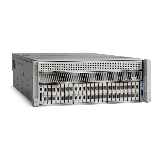
• Summary of Server Features, on page 9 Overview This chapter provides a summary overview of the Cisco UCS C480 M5 server. External Features This topic shows the external features of the server. Cisco UCS C480 M5 Server Front Panel Features... - Page 4 • Bays 19, 20, 21, 22 support SAS/SATA drives only. Fan status LED KVM console connector (used with a KVM cable that provides two USB, one VGA, and one serial connector) Temperature status LED Pull-out asset tag Cisco UCS C480 M5 Server Installation and Service Guide...
- Page 5 Cisco UCS C480 M5 Server Rear Panel Features For definitions of LED states, see Rear-Panel LEDs, on page Figure 2: Cisco UCS C480 M5 Server Rear Panel Serial port COM 1 (DB-9 connector) Rear identification button/LED VGA video port (DB-15 connector) USB 3.0 ports (three)
-
Page 6: Table Of Contents
(scroll down to Technical Specifications). • Serviceable Components Inside the Main Chassis, on page 5 • Serviceable Components Inside a CPU Module, on page 8 • Serviceable Components Inside an I/O Module, on page 9 Cisco UCS C480 M5 Server Installation and Service Guide... -
Page 7: Serviceable Components Inside The Main Chassis
Overview Serviceable Component Locations Serviceable Components Inside the Main Chassis Figure 3: Serviceable Component Locations Inside the Main Chassis Cisco UCS C480 M5 Server Installation and Service Guide... - Page 8 • Up to eight 2.5-inch SAS/SATA drives NVMe drives. Front NVMe drives are not supported in a • Up to eight 2.5-inch NVMe SSDs single-CPU module system. • Bays 11, 12, 13, 14 support SAS/SATA drives only. Cisco UCS C480 M5 Server Installation and Service Guide...
- Page 9 PCIe slot 10: Required slot for NVMe switch card when the rear drive module is used with NVMe SSDs. This slot must also be used for the rear RAID controller in systems with only one CPU module. Cisco UCS C480 M5 Server Installation and Service Guide...
-
Page 10: Serviceable Components Inside A Cpu Module
DIMM sockets controlled by CPU 2 or 4 (channels Release levers for module (two each module) G, H, J, K, L, M.) DIMM Population Rules and Memory Performance Guidelines, on page 108 for DIMM slot numbering. Cisco UCS C480 M5 Server Installation and Service Guide... -
Page 11: Serviceable Components Inside An I/O Module
M.2 SSD carrier with two SATA M.2 SSD slots. Summary of Server Features The following table lists a summary of server features. Feature Description Chassis Four rack-unit (4RU) chassis Cisco UCS C480 M5 Server Installation and Service Guide... - Page 12 Baseboard management BMC, running Cisco Integrated Management Controller (Cisco IMC) firmware. Depending on your Cisco IMC settings, Cisco IMC can be accessed through the 1-Gb dedicated management port, the 1-Gb/10-Gb Ethernet LAN ports, or a Cisco virtual interface card. Network and management I/O...
-
Page 13: 10/100/1000 Ethernet Dedicated Management Port
• SD card carrier. Supports up to two SD cards. • M.2 SSD carrier. Supports two SATA M.2 SSDs. • One micro-SD card socket on the I/O module board. Cisco UCS C480 M5 Server Installation and Service Guide... - Page 14 RAID controller for front-loading drives. • There is a bracket on the rear drive module diffuser for a supercap unit that backs up a rear RAID controller. Integrated video Integrated VGA video. Cisco UCS C480 M5 Server Installation and Service Guide...
-
Page 15: Preparing For Installation
Initial Server Setup, on page 20 • NIC Mode and NIC Redundancy Settings, on page 25 • Updating the BIOS and Cisco IMC Firmware, on page 26 • Accessing the System BIOS, on page 27 Preparing for Installation This section contains the following topics:... -
Page 16: Statement
(equipotential earth) and the system is connected to a grounded electrical outlet. Statement 328 Warning High leakage current – earth connection essential before connection to system power supply. Statement 342 Cisco UCS C480 M5 Server Installation and Service Guide... -
Page 17: Rack Requirements
Caution Avoid uninterruptible power supply (UPS) types that use ferroresonant technology. These UPS types can become unstable with systems such as the Cisco UCS, which can have substantial current draw fluctuations from fluctuating data traffic patterns. When you are installing a server, use the following guidelines: •... -
Page 18: Installing The Server In A Rack
• Cisco part UCSC-CMA-4U-M5= (cable management arm) Rack Installation Tools Required The slide rails sold by Cisco Systems for this server do not require tools for installation. Slide Rail and Cable Management Arm Dimensions The slide rails for this server have an adjustment range of 24 to 36 inches (610 to 914 mm). - Page 19 The slide rail front-end wraps around the outside of the rack post and the mounting pegs enter the rack-post holes from the outside-front. The rack post must be between the mounting pegs and the open securing plate. Note Cisco UCS C480 M5 Server Installation and Service Guide...
- Page 20 The screw threads into the static part of the rail on the rack post and prevents the server from being pulled out. Repeat for the opposite slam latch. Cisco UCS C480 M5 Server Installation and Service Guide...
- Page 21 Slide the CMA tab that is at the end of the width-adjustment slider onto the end of the stationary slide rail that is attached to the rack post. Slide the tab over the end of the rail until it clicks and locks. Cisco UCS C480 M5 Server Installation and Service Guide...
-
Page 22: Initial Server Setup
This section describes how to power on the server, assign an IP address, and connect to server management when using the server in standalone mode. To use the server in Cisco UCS Manager integration, specific cabling and settings are required. See Installation For Cisco UCS Manager Integration, on page 161. - Page 23 There are two methods for connecting to the system for initial setup: • Local setup—Use this procedure if you want to connect a keyboard and monitor directly to the system for setup. This procedure can use a KVM cable (Cisco PID N20-BKVM) or the ports on the rear of the server.
- Page 24 Connect a USB keyboard and VGA monitor to the server using one of the following methods: • Connect an optional KVM cable (Cisco PID N20-BKVM) to the KVM connector on the front panel. Connect your USB keyboard and VGA monitor to the KVM cable.
- Page 25 Allow your preconfigured DHCP server to assign an IP address to the server node. Step 4 Use the assigned IP address to access and log in to the Cisco IMC for the server node. Consult with your DHCP server administrator to determine the IP address.
- Page 26 Setting Up the System With the Cisco IMC Configuration Utility In this NIC mode, DHCP replies are returned to both the shared LOM ports and the Cisco card ports. If the system determines that the Cisco card connection is not getting its IP address from a Cisco UCS Manager system because the server is in standalone mode, further DHCP requests from the Cisco card are disabled.
- Page 27 What to do next Use a browser and the IP address of the Cisco IMC to connect to the Cisco IMC management interface. The IP address is based upon the settings that you made (either a static address or the address assigned by your DHCP server).
-
Page 28: Updating The Bios And Cisco Imc Firmware
When you upgrade the BIOS firmware, you must also upgrade the Cisco IMC firmware to the same version or the server does not boot. Do not power off the server until the BIOS and Cisco IMC firmware are matching or the server does not boot. -
Page 29: Accessing The System Bios
See the Cisco Host Upgrade Utility Quick Reference Guide for your firmware release at the documentation roadmap link below. • You can upgrade the Cisco IMC and BIOS firmware by using the Cisco IMC GUI interface. See the Cisco UCS C-Series Rack-Mount Server Configuration Guide. - Page 30 Installing the Server Accessing the System BIOS Cisco UCS C480 M5 Server Installation and Service Guide...
-
Page 31: Maintaining The Server
Service DIP Switches, on page 118 Status LEDs and Buttons This section contains information for interpreting LED states. Front-Panel LEDs Figure 11: Front Panel LEDs Table 2: Front Panel LEDs, Definition of States LED Name States Cisco UCS C480 M5 Server Installation and Service Guide... - Page 32 • Green—All fan modules are operating properly. • Amber, steady—Fan modules are in a degraded state. One fan module has a fault. • Amber, blinking—Two or more fan modules have faults. Cisco UCS C480 M5 Server Installation and Service Guide...
- Page 33 • Amber—The drive has failed. • Amber, blinking—A drive Locate command has been issued in the software. NVMe SSD activity • Off—No drive activity. NVMe • Green, blinking—There is drive activity. Cisco UCS C480 M5 Server Installation and Service Guide...
- Page 34 1-Gb/10-Gb Ethernet link speed (on both LAN1 and • Off—Link speed is 100 Mbps. LAN2) • Amber—Link speed is 1 Gbps. These ports auto-negotiate link speed based on the • Green—Link speed is 10 Gbps. link-partner capability. Cisco UCS C480 M5 Server Installation and Service Guide...
-
Page 35: Internal Diagnostic Leds
The contents of the registers are preserved for a limited time by a supercap voltage source. To operate the LEDs, press switch SW1 on the board after the CPU module is removed from the chassis. Cisco UCS C480 M5 Server Installation and Service Guide... -
Page 36: Preparing For Component Installation
This section includes information and tasks that help prepare the server for component installation. Required Equipment For Service Procedures The following tools and equipment are used to perform the procedures in this chapter: • T-30 Torx driver (supplied with replacement CPUs for heatsink removal) Cisco UCS C480 M5 Server Installation and Service Guide... - Page 37 If a service procedure instructs you to completely remove power from the server, disconnect all power cords from the power supplies in the server. Shutting Down Using The Cisco IMC GUI You must log in with user or admin privileges to perform this task. Cisco UCS C480 M5 Server Installation and Service Guide...
- Page 38 Step 6 If a confirmation dialog displays, click Yes. The operating system performs a graceful shutdown and the server goes to standby mode, which is indicated by an amber Power button/LED. Cisco UCS C480 M5 Server Installation and Service Guide...
-
Page 39: Removing The Server Top Cover
Press the cover latch down to the closed position. The cover is pushed forward to the closed position as you push down the latch. c) If desired, lock the latch by using a screwdriver to turn the lock 90-degrees clockwise. Cisco UCS C480 M5 Server Installation and Service Guide... -
Page 40: Serial Number Location
• Hot-swap replacement—You do not have to shut down the component in the software or operating system. This applies to the following components: • SAS/SATA hard drives • SAS/SATA solid state drives • Cooling fan modules • Power supplies (when redundant as 2+2 or 1+1) Cisco UCS C480 M5 Server Installation and Service Guide... -
Page 41: Serviceable Component Locations
(scroll down to Technical Specifications). • Serviceable Components Inside the Main Chassis, on page 40 • Serviceable Components Inside a CPU Module, on page 43 • Serviceable Components Inside an I/O Module, on page 44 Cisco UCS C480 M5 Server Installation and Service Guide... - Page 42 Maintaining the Server Serviceable Component Locations Serviceable Components Inside the Main Chassis Figure 15: Serviceable Component Locations Inside the Main Chassis Cisco UCS C480 M5 Server Installation and Service Guide...
- Page 43 • Up to eight 2.5-inch SAS/SATA drives NVMe drives. Front NVMe drives are not supported in a • Up to eight 2.5-inch NVMe SSDs single-CPU module system. • Bays 11, 12, 13, 14 support SAS/SATA drives only. Cisco UCS C480 M5 Server Installation and Service Guide...
- Page 44 PCIe slot 10: Required slot for NVMe switch card when the rear drive module is used with NVMe SSDs. This slot must also be used for the rear RAID controller in systems with only one CPU module. Cisco UCS C480 M5 Server Installation and Service Guide...
- Page 45 DIMM sockets controlled by CPU 2 or 4 (channels Release levers for module (two each module) G, H, J, K, L, M.) DIMM Population Rules and Memory Performance Guidelines, on page 108 for DIMM slot numbering. Cisco UCS C480 M5 Server Installation and Service Guide...
-
Page 46: Replacing Components Inside The Main Chassis
Do not operate the system unless all cards, faceplates, front covers, and rear covers are in place. Statement 1029 Cisco UCS C480 M5 Server Installation and Service Guide... -
Page 47: Replacing A Cpu Module
• If a rear RAID controller is used, it must be installed in PCIe slot 10 rather than the default slot 11. A blank filler must be installed in slot 11. Cisco UCS C480 M5 Server Installation and Service Guide... - Page 48 Push the module into the bay until it engages with the midplane connectors and is flush with the chassis front. c) Rotate both ejector levers toward the center until they lay flat and their latches lock into the front of the module. Cisco UCS C480 M5 Server Installation and Service Guide...
- Page 49 • Center drive bay module: Bays 9, 10, 15, 16 support SAS/SATA or NVMe drives; bays 11, 12, 13, 14 support SAS/SATA drives only. • Right bay module: Bays 17, 18, 23, 24 support SAS/SATA or NVMe drives; bays 19, 20, 21, 22 support SAS/SATA drives only. Cisco UCS C480 M5 Server Installation and Service Guide...
- Page 50 Under Boot Option Priorities, verify that the OS you installed is listed as your Boot Option #1. Setting Up UEFI Mode Booting in the Cisco IMC GUI Step 1 Use a web browser and the IP address of the server to log into the Cisco IMC GUI management interface. Step 2 Navigate to Server > BIOS.
- Page 51 With the ejector lever on the drive tray open, insert the drive tray into the empty drive bay. c) Push the tray into the slot until it touches the backplane, and then close the ejector lever to lock the drive in place. Cisco UCS C480 M5 Server Installation and Service Guide...
- Page 52 You do not have to shut down the server or drive to replace SAS/SATA hard drives or SSDs because they are hot-swappable. Rear SAS/SATA Drive Population Guidelines The server supports an internal, rear drive module that holds up to eight 2.5-inch drives. Cisco UCS C480 M5 Server Installation and Service Guide...
- Page 53 Rear SAS/SATA Drive Requirements Observe these requirements: • The optional, rear drive module (UCSC-C480-8HDD). • The rear drive module requires minimum Cisco IMC and BIOS 3.1(3) or later. • The rear drive-bay module must have air-diffuser UCSC-DIFF-C480M5 installed when SAS/SATA drives are installed.
- Page 54 Reconnect power cords to all power supplies and then allow the server to boot to standby power mode (indicated when the front panel Power button LED lights amber). Step 6 Fully power on the server by pressing the Power button. Cisco UCS C480 M5 Server Installation and Service Guide...
- Page 55 OS-informed hot-insertion and hot-removal must be enabled in the system BIOS. See Enabling Hot-Plug Support in the System BIOS, on page Note OS-surprise removal is not supported. OS-informed hot-insertion and hot-removal are supported on all supported operating systems except VMware ESXi. Cisco UCS C480 M5 Server Installation and Service Guide...
- Page 56 • Right drive-bay module: Bays 17, 18, 23, 24 support SAS/SATA or NVMe drives; bays 19, 20, 21, 22 support SAS/SATA drives only. Front NVMe drives are not supported in a single-CPU module system. • UCSC-C480-8NVME: NVMe-only drive bay modules. All eight bays support only NVMe drives. Cisco UCS C480 M5 Server Installation and Service Guide...
- Page 57 Setting Up UEFI Mode Booting in the BIOS Setup Utility, on page 48 Setting Up UEFI Mode Booting in the Cisco IMC GUI, on page • You cannot control NVMe PCIe SSDs with a SAS RAID controller because NVMe SSDs interface with the server via the PCIe bus.
- Page 58 Save your changes and exit the utility. Enabling Hot-Plug Support Using the Cisco IMC GUI Step 1 Use a browser to log in to the Cisco IMC GUI for the server. Step 2 Navigate to Compute > BIOS > Advanced > PCI Configuration.
- Page 59 • Green—The drive is in use and functioning properly. Figure 24: Replacing a Drive in a Drive Tray Ejector lever Drive tray screws (two on each side) Release button Drive removed from drive tray Cisco UCS C480 M5 Server Installation and Service Guide...
- Page 60 • When populating drives, add drives to the lowest-numbered bays first. • Keep an empty drive blanking tray in any unused bays to ensure proper airflow. Figure 25: Internal Drive Module Bays (Top View) Cisco UCS C480 M5 Server Installation and Service Guide...
- Page 61 Setting Up UEFI Mode Booting in the BIOS Setup Utility, on page 48 Setting Up UEFI Mode Booting in the Cisco IMC GUI, on page • You cannot control NVMe PCIe SSDs with a SAS RAID controller because NVMe SSDs interface with the server via the PCIe bus.
- Page 62 Reconnect power cords to all power supplies and then allow the server to boot to standby power mode (indicated when the front panel Power button LED lights amber). Step 7 Fully power on the server by pressing the Power button. Cisco UCS C480 M5 Server Installation and Service Guide...
- Page 63 HHHL SSD Population Guidelines Observe the following population guidelines when installing HHHL form-factor NVMe SSDs: • Dual CPU-Module systems—You can populate up to 12 HHHL form-factor SSDs, using PCIe slots 1 – Cisco UCS C480 M5 Server Installation and Service Guide...
- Page 64 Remove any existing HHHL drive from the slot (or a blanking panel): a) Open the hinged retainer bar that covers the top of the PCIe slot from which you are removing the HHHL drive. Cisco UCS C480 M5 Server Installation and Service Guide...
- Page 65 Replacing a Front Drive Bay Module The front drive bays are divided across three removable drive bay modules that have eight bays each. There are two types of drive bay modules: • SAS/SATA and NVMe (UCSC-C480-8HDD) Cisco UCS C480 M5 Server Installation and Service Guide...
- Page 66 Reconnect power cords to all power supplies and then allow the server to boot to standby power mode (indicated when the front panel Power button LED lights amber). Step 12 Fully power on the server by pressing the Power button. Cisco UCS C480 M5 Server Installation and Service Guide...
- Page 67 Maintaining the Server Replacing a Front Drive Bay Module Figure 28: Front Drive-Bay Module Securing Screws (CPU Modules Removed) Cisco UCS C480 M5 Server Installation and Service Guide...
- Page 68 Host Upgrade Utility (HUU) for your firmware release to bring it to a compatible level. See the HUU guide for your Cisco IMC release for instructions on downloading and using the utility to bring server components to compatible levels: Guides.
- Page 69 Fully power on the server by pressing the Power button. Step 9 If your server is running in standalone mode, use the Cisco UCS Host Upgrade Utility to update the controller firmware and program the correct suboem-id for the controller.
- Page 70 This server supports installation of up to two supercap units, one for a front RAID controller and one for a rear RAID controller. The front supercap unit mounts to a bracket on the inner chassis wall, below the CPU modules. Cisco UCS C480 M5 Server Installation and Service Guide...
- Page 71 Reconnect power cords to all power supplies and then allow the server to boot to standby power mode (indicated when the front panel Power button LED lights amber). Step 8 Fully power on the server by pressing the Power button. Cisco UCS C480 M5 Server Installation and Service Guide...
- Page 72 Maintaining the Server Replacing the Front RAID Supercap Unit Figure 30: Front Supercap Bracket Location (Below CPU Modules) Cisco UCS C480 M5 Server Installation and Service Guide...
- Page 73 Maintaining the Server Replacing the Front RAID Supercap Unit Cisco UCS C480 M5 Server Installation and Service Guide...
- Page 74 In a system with only one CPU module, an additional filler panel is required in PCIe slot 11 to ensure Note adequate air flow. See Replacing a Rear RAID Controller Card, on page 77 for more information. f) Install your drives to the bays in the new module. Cisco UCS C480 M5 Server Installation and Service Guide...
- Page 75 The air diffuser UCSC-BAFF-C480-M5 must be installed on the rear drive module when SAS/SATA hard drives or solid state drives are installed. The diffuser includes a clip for the rear supercap unit on its inside surface. Cisco UCS C480 M5 Server Installation and Service Guide...
- Page 76 Reconnect power cords to all power supplies and then allow the server to boot to standby power mode (indicated when the front panel Power button LED lights amber). Step 6 Fully power on the server by pressing the Power button. Cisco UCS C480 M5 Server Installation and Service Guide...
- Page 77 The supercap provides approximately three years of backup for the disk write-back cache DRAM in the case of a sudden power loss by offloading the cache to the NAND flash. Cisco UCS C480 M5 Server Installation and Service Guide...
- Page 78 Reconnect power cords to all power supplies and then allow the server to boot to standby power mode (indicated when the front panel Power button LED lights amber). Step 6 Fully power on the server by pressing the Power button. Cisco UCS C480 M5 Server Installation and Service Guide...
- Page 79 In this case, install the rear RAID controller in PCIe slot 10 and install the required blank filler to PCIe slot 11 to ensure adequate air flow. For detailed information about storage controllers in this server, see Supported Storage Controllers and Cables, on page 133. Cisco UCS C480 M5 Server Installation and Service Guide...
- Page 80 Host Upgrade Utility (HUU) for your firmware release to bring it to a compatible level. See the HUU guide for your Cisco IMC release for instructions on downloading and using the utility to bring server components to compatible levels: Guides.
- Page 81 Slide the server out the front of the rack far enough so that you can remove the top cover. You might have to detach cables from the rear panel to provide clearance. Caution If you cannot safely view and access the component, remove the server from the rack. Cisco UCS C480 M5 Server Installation and Service Guide...
- Page 82 Reconnect power cords to all power supplies and then allow the server to boot to standby power mode (indicated when the front panel Power button LED lights amber). Step 6 Fully power on the server by pressing the Power button. Figure 35: Rear NVMe Switch Card Location (PCIe 10) Cisco UCS C480 M5 Server Installation and Service Guide...
-
Page 83: Replacing Fan Modules
Press down gently on the fan module to fully engage it with the connector on the motherboard. c) Replace the top cover to the server. d) Replace the server in the rack. Cisco UCS C480 M5 Server Installation and Service Guide... - Page 84 Slide the server out the front of the rack far enough so that you can remove the top cover. You might have to detach cables from the rear panel to provide clearance. Caution If you cannot safely view and access the component, remove the server from the rack. Cisco UCS C480 M5 Server Installation and Service Guide...
- Page 85 Step 1 Enter the BIOS Setup Utility by pressing the F2 key when prompted during bootup. Step 2 Navigate to the Advanced tab. Step 3 On the Advanced tab, select USB Configuration. Cisco UCS C480 M5 Server Installation and Service Guide...
- Page 86 Step 1 Prepare the server for component installation: a) Shut down and remove power from the server as described in Shutting Down and Removing Power From the Server, on page Cisco UCS C480 M5 Server Installation and Service Guide...
- Page 87 Enabling the TPM in the BIOS, on page Figure 38: TPM Socket Location TPM socket location on motherboard Enabling the TPM in the BIOS After hardware installation, you must enable TPM support in the BIOS. Cisco UCS C480 M5 Server Installation and Service Guide...
- Page 88 Verify that the following items are listed as Enabled: • VT-d Support (default is Enabled) • VT Support (default is Enabled) • TPM Support • TPM State d) Do one of the following: Cisco UCS C480 M5 Server Installation and Service Guide...
- Page 89 Reconnect power cords to all power supplies and then allow the server to boot to standby power mode (indicated when the front panel Power button LED lights amber). Step 6 Fully power on the server by pressing the Power button. Cisco UCS C480 M5 Server Installation and Service Guide...
-
Page 90: Replacing Power Supplies
Step 1 Remove the power supply that you are replacing or a blank panel from an empty bay: a) Remove the power cord from the power supply that you are replacing. Cisco UCS C480 M5 Server Installation and Service Guide... -
Page 91: Replacing A Pcie Card
Replacing a PCIe Card Note Cisco supports all PCIe cards qualified and sold by Cisco. PCIe cards not qualified or sold by Cisco are the responsibility of the customer. Although Cisco will always stand behind and support the C-Series rack-mount servers, customers using standard, off-the-shelf, third-party cards must go to the third-party card vendor for support if any issue with that particular card occurs. - Page 92 Connector Maximum Card Card Height NCSI GPU Card Cisco VIC Number Width Length Length (Rear Panel Support Support Card Support Opening) Gen-3 x16 x24 connector Full length Full height (primary slot) Cisco UCS C480 M5 Server Installation and Service Guide...
- Page 93 • If the server has a rear NVMe switch card, it must be installed in PCIe slot 10. Replacing a PCIe Card Before installing PCIe cards, see PCIe Slot Specifications and Restrictions, on page Cisco UCS C480 M5 Server Installation and Service Guide...
- Page 94 Reconnect power cords to all power supplies and then allow the server to boot to standby power mode (indicated when the front panel Power button LED lights amber). Step 6 Fully power on the server by pressing the Power button. Cisco UCS C480 M5 Server Installation and Service Guide...
- Page 95 Cisco Virtual Interface Card (VIC) Considerations This section describes VIC card support and special considerations for this server. If you want to use the Cisco UCS VIC card for Cisco UCS Manager integration, see also the Installation For Cisco UCS Manager Integration, on page 161 for details about supported configurations, cabling, and other requirements.
-
Page 96: Replacing Components Inside A Cpu Module
• The server can operate with one or two CPU modules (two or four identical CPUs) installed. Note The CPUs in CPU module 1 must be identical with the CPUs in CPU module 2 (no mixing). Cisco UCS C480 M5 Server Installation and Service Guide... - Page 97 • Heatsink cleaning kit—Supplied with replacement CPU. Orderable separately as Cisco PID UCSX-HSCK=. • Thermal interface material (TIM)—Syringe supplied with replacement CPU. Use only if you are reusing your existing heatsink (new heatsinks have a pre-applied pad of TIM). Orderable separately as Cisco PID UCS-CPU-TIM=. See also Additional CPU-Related Parts to Order with RMA Replacement CPUs, on page 102.
- Page 98 Alternate loosening the heatsink nuts evenly so that the heatsink remains level as it is raised. Loosen the heatsink nuts in the order shown on the heatsink label: 4, 3, 2, 1. b) Lift straight up on the CPU/heatsink assembly and set it heatsink-down on an antistatic surface. Cisco UCS C480 M5 Server Installation and Service Guide...
- Page 99 Place the heatsink with CPU assembly so that it is oriented upside-down as shown in the following figure. Note the thermal-interface material (TIM) breaker location. TIM BREAKER is stamped on the CPU carrier next to a small slot. Cisco UCS C480 M5 Server Installation and Service Guide...
- Page 100 On the remaining two corners of the CPU carrier, gently pry outward on the outer-latches and then lift the CPU-assembly from the heatsink. Note Handle the CPU-assembly by the plastic carrier only. Do not touch the CPU surface. Do not separate the CPU from the plastic carrier. Cisco UCS C480 M5 Server Installation and Service Guide...
- Page 101 Angled corner on CPU assembly tool (pin 1 alignment feature) Step 6 Apply new TIM to the heatsink: Note The heatsink must have new TIM on the heatsink-to-CPU surface to ensure proper cooling and performance. Cisco UCS C480 M5 Server Installation and Service Guide...
- Page 102 Note the alignment features. The pin 1 angled corner on the heatsink must align with the pin 1 angled corner on the CPU socket. The CPU-socket posts must align with the guide-holes in the assembly. Cisco UCS C480 M5 Server Installation and Service Guide...
- Page 103 Rotate both ejector levers toward the center until they lay flat and their latches lock into the front of the module. Step 10 Reconnect power cords to all power supplies and then allow the server to boot to standby power mode (indicated when the front panel Power button LED lights amber). Cisco UCS C480 M5 Server Installation and Service Guide...
- Page 104 Additional CPU-Related Parts to Order with RMA Replacement CPUs When a return material authorization (RMA) of the CPU is done on a Cisco UCS C-Series server, additional parts might not be included with the CPU spare. The TAC engineer might need to add the additional parts to the RMA to help ensure a successful replacement.
- Page 105 4, 3, 2, 1. b) Lift straight up on the CPU/heatsink assembly to remove it from the board. c) Set the CPUs with heatsinks aside on an anti-static surface. Cisco UCS C480 M5 Server Installation and Service Guide...
- Page 106 Remove the socket covers from the replacement system. Grasp the two recessed finger-grip areas marked "REMOVE" and lift straight up. Keep a firm grasp on the finger-grip areas at both ends of the cover. Do not make contact with the CPU Note socket pins. Cisco UCS C480 M5 Server Installation and Service Guide...
- Page 107 Press until you feel and hear a click. Note You must press until you feel and hear a click to ensure that the dust covers do not come loose during shipping. Cisco UCS C480 M5 Server Installation and Service Guide...
- Page 108 Note the alignment features. The pin 1 angled corner on the heatsink must align with the pin 1 angled corner on the CPU socket. The CPU-socket posts must align with the guide-holes in the assembly. Cisco UCS C480 M5 Server Installation and Service Guide...
- Page 109 CPU socket lie flat. Replacing Memory DIMMs Caution DIMMs and their sockets are fragile and must be handled with care to avoid damage during installation. Cisco UCS C480 M5 Server Installation and Service Guide...
- Page 110 Maintaining the Server DIMM Population Rules and Memory Performance Guidelines Caution Cisco does not support third-party DIMMs. Using non-Cisco DIMMs in the server might result in system problems or damage to the motherboard. Note To ensure the best server performance, it is important that you are familiar with memory performance guidelines and population rules before you install or replace DIMMs.
- Page 111 • AMD FirePro S7150 X2 GPUs can support only less-than 1 TB memory in the server. • Observe the DIMM mixing rules shown in the following table. Table 7: DIMM Mixing Rules DIMM Parameter DIMMs in the Same Channel DIMMs in the Same Bank Cisco UCS C480 M5 Server Installation and Service Guide...
-
Page 112: Replacing Dimms
Remove an existing DIMM (or DIMM blank) from the CPU module: a) Locate the DIMM that you are removing, and then open the ejector levers at each end of its DIMM slot. Step 4 Install a new DIMM: Cisco UCS C480 M5 Server Installation and Service Guide... -
Page 113: Replacing Components Inside An I/O Module
PCIe module in the same chassis, as shipped from the factory. See also: • Replacing Components Inside the Main Chassis, on page 44 • Replacing Components Inside a CPU Module, on page 94 Cisco UCS C480 M5 Server Installation and Service Guide... -
Page 114: Replacing The Rtc Battery
The real-time clock (RTC) battery retains system settings when the server is disconnected from power. The battery type is CR2032. Cisco supports the industry-standard CR2032 battery, which can be ordered from Cisco (PID N20-MBLIBATT) or purchased from most electronic stores. - Page 115 Push down on the locking clip on the I/O module's ejector-handle, and then hinge the handle upward to disengage the module's connector from the chassis midplane. c) Pull the module straight out from the chassis and then set it on an antistatic surface. Cisco UCS C480 M5 Server Installation and Service Guide...
- Page 116 • SD card carrier—provides two SD card sockets. • M.2 SSD Carrier—provides two M.2 form-factor SSD sockets. These M.2 SSDs can be two SATA SSDs (no mixing). Cisco UCS C480 M5 Server Installation and Service Guide...
- Page 117 Gently push down the socket end of the carrier so that the two pegs go through the two holes on the carrier. d) Push down on the carrier so that the securing clips click over it at both ends. Cisco UCS C480 M5 Server Installation and Service Guide...
- Page 118 • You can use one or two SD cards in the carrier. • Dual SD cards can be configured in a RAID 1 array through the Cisco IMC interface. • SD socket 1 is on the top side of the carrier; SD socket 2 is on the underside of the carrier (the same side as the carrier's motherboard connector).
- Page 119 You cannot control the M.2 SATA SSDs in the server with a HW RAID controller. Note The embedded SATA RAID controller requires that the server is set to boot in UEFI mode rather than Legacy mode. Cisco UCS C480 M5 Server Installation and Service Guide...
-
Page 120: Service Dip Switches
115. Service DIP Switches This server includes a block of DIP switches (SW1) that you can use for certain service and Cisco IMC debug functions. The block is located on the chassis motherboard, as shown in the following figure. The switches in the following figure are shown in the default, open position (off). - Page 121 3 - 14 Recover BIOS 2 - 15 Password clear 1 - 16 Using the Clear Password Switch (Positions 1 - 16) You can use this switch to clear the administrator password. Cisco UCS C480 M5 Server Installation and Service Guide...
- Page 122 • If it is a non-BootBlock corruption, a message similar to the following is displayed: ****BIOS FLASH IMAGE CORRUPTED**** Flash a valid BIOS capsule file using Cisco IMC WebGUI or CLI interface. IF Cisco IMC INTERFACE IS NOT AVAILABLE, FOLLOW THE STEPS MENTIONED BELOW.
- Page 123 During the BIOS update, Cisco IMC shuts down the server and the screen goes blank for about 10 minutes. Do not unplug the power cords during this update. Cisco IMC powers on the server after the update is complete. Procedure 2: Use BIOS Recovery Switch and recovery.cap File Step 1 Download the BIOS update package and extract it to a temporary location.
- Page 124 Reconnect power cords to all power supplies and allow the server to boot to standby power. You do not have to return the server to main power for the change to take effect. Only Cisco IMC (the BMC) must reboot. The change takes effect after Cisco IMC finishes booting.
- Page 125 Power LED on the front panel is amber. You do not have to return the server to main power for the change to take effect. Only Cisco IMC (the BMC) must reboot. The change takes effect after Cisco IMC finishes booting.
- Page 126 Power LED on the front panel is amber. You do not have to return the server to main power for the change to take effect. Only Cisco IMC (the BMC) must reboot. The change takes effect after Cisco IMC finishes booting.
- Page 127 Power LED on the front panel is amber. You do not have to return the server to main power for the change to take effect. Only Cisco IMC (the BMC) must reboot. The change takes effect after Cisco IMC finishes booting.
- Page 128 Maintaining the Server Using the Boot Alternate Cisco IMC Image Switch (Positions 8 - 9) Cisco UCS C480 M5 Server Installation and Service Guide...
- Page 129 Depth (length including front handles and power supplies) 31.0 in. (830.0 Maximum weight (fully loaded chassis) 146 lb. (66.2 Kg) Environmental Specifications The following table lists the environmental requirements and specifications for the server. Cisco UCS C480 M5 Server Installation and Service Guide...
-
Page 130: Power Specifications
Power Specifications Note Do not mix power supply types or wattages in the server. Both power supplies must be identical. You can get more specific power information for your exact server configuration by using the Cisco UCS Power Calculator: http://ucspowercalc.cisco.com The power specifications for the supported power supply options are listed in the following sections. -
Page 131: Power Cord Specifications
Only the approved power cords or jumper power cords listed below are supported. Table 11: Supported Power Cords Description Length Length (Feet) (Meters) CAB-250V-10A-AR AC power cord, 250 V, 10 A Argentina Cisco UCS C480 M5 Server Installation and Service Guide... - Page 132 AC power cord, 250 V, 10 A, 3112 plug, Australia CAB-250V-10A-ID AC power Cord, 250 V, 10 A, India CAB-9K10A-SW AC power cord, 250 V, 10 A, MP232 plug Switzerland CAB-250V-10A-BR AC power Cord, 250 V, 10 A Brazil Cisco UCS C480 M5 Server Installation and Service Guide...
- Page 133 AC power cord, NEMA L6-20 to C13 connectors CAB-9K10A-IT AC power cord, 250 V, 10 A, CEI 23-16/VII plug Italy R2XX-DMYMPWRCORD No power cord; PID option for ordering server with no power cord Cisco UCS C480 M5 Server Installation and Service Guide...
- Page 134 Server Specifications Server Specifications Cisco UCS C480 M5 Server Installation and Service Guide...
-
Page 135: Supported Storage Controllers And Cables
Storage Controller Card Firmware Compatibility, on page 134 • RAID Backup (Supercap), on page 134 • Write-Cache Policy for Cisco 12G SAS Modular RAID Controllers, on page 134 • Mixing Drive Types in RAID Groups, on page 135 • Storage Controller Cable Connectors and Backplanes, on page 135 •... -
Page 136: Storage Controller Card Firmware Compatibility
Host Upgrade Utility (HUU) for your firmware release to bring it to a compatible level. See the HUU guide for your Cisco IMC release for instructions on downloading and using the utility to bring server components to compatible levels: Guides. -
Page 137: Mixing Drive Types In Raid Groups
This software RAID option controls only two internal M.2 SATA SSDs. No cabling or other hardware is required. Cisco 12G Modular SAS RAID Controller With 4-GB Cache (UCSC-RAID-M5HD) This hardware RAID option can control up to 24 front-loading SAS/SATA drives. The card plugs into a dedicated, horizontal socket on the drive midplane. -
Page 138: Embedded Sata Raid Controller
• The default setting for this embedded controller hub is SATA RAID 0 and 1 support for two M.2 SATA drives. The hub is divided into two SATA controllers that have different functions. See Embedded SATA RAID: Two SATA Controllers, on page 137. Cisco UCS C480 M5 Server Installation and Service Guide... - Page 139 Embedded SATA RAID: Two SATA Controllers The embedded RAID platform controller hub (PCH) is split into two controllers: primary SATA (pSATA) and secondary SATA (sSATA). These two controllers are seen as separate RAID controllers in the Cisco IMC interface and are configurable separately.
-
Page 140: Installing Lsi Megasr Drivers For Windows And Linux
Click the release number that you are downloading. g) Click Download to download the drivers’ ISO file. h) Verify the information on the next page, and then click Proceed With Download. Cisco UCS C480 M5 Server Installation and Service Guide... - Page 141 Windows installation disk into the DVD drive. Skip to Step 6. • To install from remote ISO, log in to the server’s Cisco IMC interface and continue with the next step. Step 4 Launch a Virtual KVM console window and click the Virtual Media tab.
- Page 142 MegaRAID stack. Note The LSI MegaSR drivers that Cisco provides for Red Hat Linux and SUSE Linux are for the original GA versions of those distributions. The drivers do not support updates to those OS kernels. Preparing Physical Thumb Drive for Linux This topic describes how to prepare physical Linux thumb drive from the driver image files.
- Page 143 RHEL installation disk into the drive. Then continue with Step 6. • To install from remote ISO, log in to the server’s Cisco IMC interface. Then continue with the next step. Cisco UCS C480 M5 Server Installation and Service Guide...
- Page 144 For the specific supported OS versions, see the Hardware and Software Compatibility Matrix for your server release. This topic describes the fresh installation of the SLES driver on systems that have the embedded MegaRAID stack. Cisco UCS C480 M5 Server Installation and Service Guide...
- Page 145 RHEL installation disk into the drive. Then continue with Step 6. • To install from remote ISO, log in to the server’s Cisco IMC interface. Then continue with the next step. Step 4 Launch a Virtual KVM console window and click the Virtual Media tab.
-
Page 146: For More Raid Utility Information
12Gb/s MegaRAID SAS Software User Guide, Version 2.8 • For embedded software MegaRAID and the utility that is accessed via the server BIOS (refer to Chapter 4)—Broadcom Embedded MegaRAID Software User Guide, March 2018. Cisco UCS C480 M5 Server Installation and Service Guide... - Page 147 NVIDIA Tesla P100 16GB 3.1(2) AMD FirePro S7150 X2 3.1(2) NVIDIA Tesla M60 3.1(2c) NVIDIA Tesla V100 3.1(3) 16GB GPU Card Configuration Rules Note the following rules when populating a server with GPU cards. Cisco UCS C480 M5 Server Installation and Service Guide...
- Page 148 • NVIDIA P-Series and V-Series GPUs can support 1 TB or more memory in the server. • AMD FirePro S7150 X2 GPUs can support only less-than 1 TB memory in the server. Figure 58: Double-Wide GPU Spacing in PCIe Slots Cisco UCS C480 M5 Server Installation and Service Guide...
- Page 149 If you need to change this setting, enter the BIOS Setup Utility by pressing F2 when prompted during bootup. • If the server is integrated with Cisco UCS Manager and is controlled by a service profile, this setting is enabled by default in the service profile when a GPU is present.
- Page 150 Y-cable. The straight cable is used for connecting power to the GPU card in this server; do not use the Y-cable, which is used for connecting the GPU card in external devices only (such as the Magma chassis). For AMD GPUs: The correct power cable is a Y-cable (UCS-AMDCBL-C480M5). Cisco UCS C480 M5 Server Installation and Service Guide...
- Page 151 NVIDIA GRID software features are not supported on the NVIDIA Tesla P4 GPU at this time. Use the topics in this section in the following order when obtaining and using NVIDIA GRID licenses. 1. Familiarize yourself with the NVIDIA GRID License Server. Cisco UCS C480 M5 Server Installation and Service Guide...
- Page 152 You obtain the licenses that are served by the GRID License Server from NVIDIA’s Licensing Portal as downloadable license files, which you install into the GRID License Server via its management interface. Cisco UCS C480 M5 Server Installation and Service Guide...
- Page 153 The NVIDIA Software Licensing Center > License Key Registration dialog opens. Step 2 Complete the License Key Registration form and then click Submit My Registration Information. The NVIDIA Software Licensing Center > Product Information Software dialog opens. Cisco UCS C480 M5 Server Installation and Service Guide...
- Page 154 Download and install the latest Java 32-bit runtime environment from https://www.oracle.com/downloads/index.html. Note Install the 32-bit Java Runtime Environment, regardless of whether your platform is Windows 32-bit or 64-bit. Step 2 Create a server interface: Cisco UCS C480 M5 Server Installation and Service Guide...
- Page 155 Unpack the License Server tar file using the following command: tar xfz NVIDIA-linux-2015.09-0001.tgz b) Run the unpacked setup binary as root: sudo ./setup.bin c) Accept the EULA and then continue with the installation wizard to finish the installation. Cisco UCS C480 M5 Server Installation and Service Guide...
- Page 156 Use the License Server Configuration menu to install the .bin file that you generated earlier. a) Click Choose File. b) Browse to the license .bin file that you want to install and click Open. c) Click Upload. Cisco UCS C480 M5 Server Installation and Service Guide...
- Page 157 IP address. Step 5 In the Port Number field, enter your port number of leave it set to the default used by the server, which is 7070. Step 6 Select Apply. Cisco UCS C480 M5 Server Installation and Service Guide...
- Page 158 # 1 => for GRID vGPU # 2 => for GRID Virtual Workstation FeatureType=2 Using gpumodeswitch The command line utility can be run in the following environments: gpumodeswitch • Windows 64-bit command prompt (requires administrator permissions) Cisco UCS C480 M5 Server Installation and Service Guide...
- Page 159 Switches to graphics mode. Switches mode of all supported GPUs in the server unless you specify otherwise when prompted. • --gpumode compute Switches to compute mode. Switches mode of all supported GPUs in the server unless you specify otherwise when prompted. Cisco UCS C480 M5 Server Installation and Service Guide...
- Page 160 1. Update the server BIOS. 2. Update the GPU drivers. 1. Updating the Server BIOS Install the latest Cisco UCS C240 M4 server BIOS by using the Host Upgrade Utility for the Cisco UCS C240 M4 server. Note You must do this procedure before you update the NVIDIA drivers.
- Page 161 Step 4 Restart the server. Step 5 Check that the virtual machine is able to recognize the GPU card. In Windows, use the Device Manager and look under Display Adapters. Cisco UCS C480 M5 Server Installation and Service Guide...
- Page 162 GPU Card Installation GPU Card Installation Cisco UCS C480 M5 Server Installation and Service Guide...
- Page 163 Refer to the guide that is for the version of Cisco UCS Manager that you are using. Also refer to the release notes for Cisco UCS Manager software and C-Series Cisco IMC software for any special considerations regarding integration in your release.
- Page 164 Installation For Cisco UCS Manager Integration Installation For Cisco UCS Manager Integration Cisco UCS C480 M5 Server Installation and Service Guide...