Kenwood DP-SE7 Service Manual
Hide thumbs
Also See for DP-SE7:
- Instruction manual (56 pages) ,
- Service manual (17 pages) ,
- Instruction manual (50 pages)
Advertisement
Quick Links
Download this manual
See also:
Instruction Manual
COMPACT DISK PLAYER
DP-SE7/SE7(G)/SE9
SERVICE MANUAL
(HM-701)
Indicator
(B12-0318-04)
on/standby
Knob
(K29-6744-04)
Metallic cabinet
(A01-3321-01)
DIGITAL OUT
L
R
PLAY OUT
Oscillating module
(W02-1114-05)
In compliance with Federal Regulations, following are reproductions of
labels on, or inside the product relating to laser product safety.
KENWOOD-Crop. certifies this equipment conforms to DHHS Regulations
No. 21 DFR 1040. 10, Chapter 1, Subchapter J.
DANGER : Laser radiation when open and interlock defeated.
AVOID DIRECT EXPOSURE TO BEAM
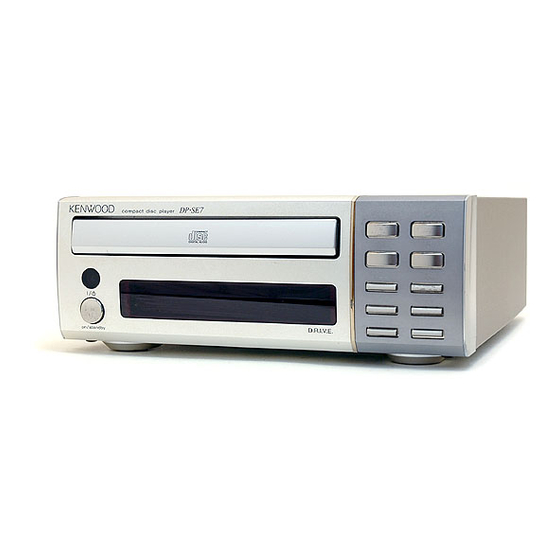
DP-SE7
compact disc player
'
Panel *
(A60-)
Rectangular receptacle
(E08-0312-05)
SYSTEM
CONTROL
OPTICAL
Phono jack
(E63-0122-05)
Panel
(A29-0872-03)
D.R.I.V.E.
Front glass
Escutcheon
(B10-2372-03)
(B07-2363-04)
Power cord bushing
(J42-0083-05)
AC power cord *
(E30-)
Refer to DP-SA7 service manual (B51-5243-00) if you require
Disassembly for repair in detail.
©1997-10/B51-5371-00 (K/K) 3191
Panel *
(A60-)
0
6
7
repeat
4
¢
1
¡
space
time
Knob
(K29-6743-03)
Illustration is DP-SE7Mtype.
* Refer to parts list on page 17.
Advertisement

Related Manuals for Kenwood DP-SE7


Summary of Contents for Kenwood DP-SE7
- Page 1 * Refer to parts list on page 17. KENWOOD-Crop. certifies this equipment conforms to DHHS Regulations No. 21 DFR 1040. 10, Chapter 1, Subchapter J. Refer to DP-SA7 service manual (B51-5243-00) if you require DANGER : Laser radiation when open and interlock defeated.
-
Page 2: Table Of Contents
DP-SE7/SE7(G)/SE9 CONTENTS / EXTERNAL VIEW Contents CONTENTS / EXTERNAL VIEW ....... 2 SCHEMATIC DIAGRAM ..........9 CIRCUIT DESCRIPTION ..........3 EXPLODED VIEW ............15 ADJUSTMENT ............6 PARTS LIST..............17 PC BOARD ..............7 SPECIFICATIONS ........Back cover Side plate Panel Knob (A50-1303-12) (A60-1266-02) (K29-6742-04) -
Page 3: Circuit Description
DP-SE7/SE7(G)/SE9 CIRCUIT DESCRIPTION 1. Microprocessor 1-1. Microprocessor periphery block diagram (X32) IC2 D.S.P. CXD 2507AQ SLT SW CLK, DTA, LAT SENSE S. CLK M. ON SCOR MUTE XLON SUBQ (SLTSW) (FOK , GFS) MOTOR CONTROL TERMINAL µPD78044FGF CD mecha SYSTEM... - Page 4 DP-SE7/SE7(G)/SE9 CIRCUIT DESCRIPTION 1-2 Pin description (uPD78044FGF-071 : X25, IC4) PIN No. PIN NAME DESCRIPTION Grid 2G~8G FL Digit control (Grid 2G~8G) Power supply (+5) SQCK Q-data read clock output. STBY Not use (OPEN) SUBQ Q-data (or SLT SW) input...
-
Page 5: Adjustment
DP-SE7/SE7(G)/SE9 CIRCUIT DESCRIPTION 2. Test mode MODE "0 0" : Use for Test or alignment Setting the test mode : While pressing the "REPEAT" key, plug the AC cord into wall output. Display Operation Remarks (1)Focus servo .........ON (2) Tracking servo ........OFF... - Page 6 DP-SE7/SE7(G)/SE9 ADJUSTMENT INPUT OUTPUT PLAYER ALIGNMENT ALIGN ITEM FIG. SETTINGS SETTINGS SETTINGS POINTS While pressing the "REPEAT" key, turn the AC ON. { Refer to test mode (MODE 0 0) } On the power from 0.08 to 0.15 mW, Press the...
- Page 7 DISPLAY UNIT (X14-4520-00) : DP-SE7..K (X14-4520-21) : DP-SE7..MET (X14-4530-21) : DP-SE9 (A/2)
-
Page 8: Pc Board
PC BOARD(Component side view) ELECTRIC UNIT (X25-6000-00) : DP-SE7 (X25-6000-01) : DP-SE9 CD PLAYER UNIT (X32-3400-00) Refer to the schematic diagram for the value of resistors and capacitors. - Page 9 CD PLAYER UNIT (X32-3400-00) : CXA1782BQ : CXD2507AQ : BA6398FP 7.1V : 2SC4081(R,S) : 2SA1611(M5,M6) or 2SA1586(Y,GR) Q3,4 : DTA124EUA or UN5112 D1-4 : MA111 : DA204U 4CH BTL DRIVER (BOTTOM VIEW) 2.3V 2.5V 3.2V 7.1V SPINDLE MOTOR 3.6V SLED MOTOR 7.1V MGND...
- Page 10 ELECTRIC UNIT (X25-6000-XX) MODEL NAME UNIT No. 1pin 2pin DP-SE7/SE7(G) X14-4520-21 DP-SE9 X14-4530-21 4.7K 4.7K OPEN: 0V CLOSE: 4.7V OPEN: 4.7V CLOSE: 0V R108 LOADING MOTOR 4.5V DRIVER SENS -30V AVR -27.5V (SE7) R107 4.5V -5.7V DATA -29.5V (SE9) -30V -30V 4.7V...
- Page 11 DISPLAY UNIT (X14-4520-21) (B/2) : DP-SE7/DP-SE7(G) CAUTION: For continued safety, replace safety critical components only (X14-4530-21) (B/2) : DP-SE9 with manufacturer's recommended parts (refer to parts list). indicates safety critical components. For continued protection against risk of fire, MODEL NAME UNIT No.
-
Page 12: Exploded View
DP-SE7/SE7(G)/SE9 EXPLODED VIEW (MECHANISM) Parts with exploded numbers larger than 700 are not supplied. -
Page 13: Time Space Repeat
(DP-SE9) X32-3400 (20P) (DP-SE9) time space repeat on/standby (27P) 645x2 X14-4530 (A/2) (27P) (20P) (27P) X14-4520 (B/2) (DP-SE7) SYSTEM ø3x6(BLK) : N09-1445-05 CONTROL repeat X25-6000-00 ø3x8 : N09-1522-05 ø2.6x8 : N82-2608-46 OPTICAL ø3x6 : N89-3006-46 ø3x8(BLK) : N89-3008-45 LINE OUT PUT... -
Page 14: Side Plate
R : Mexico T1 : GRAY L : Scandinavia K : USA P : Canada R : Mexico 7 : DP-SE7 Y : PX(Far East, Hawaii) T : Europe E : Europe G : Germany T2 : GOLD Y : PX(Far East, Hawaii) - Page 15 1/10W DTC124EUA DIGITAL TRANSISTOR L : Scandinavia K : USA P : Canada R : Mexico 7 : DP-SE7 L : Scandinavia K : USA P : Canada R : Mexico 7 : DP-SE7 Y : PX(Far East, Hawaii) T : Europe...
- Page 16 SEMI FIXED VARIABLE RESISTOR E40-3251-05 PIN ASSY L : Scandinavia K : USA P : Canada R : Mexico 7 : DP-SE7 L : Scandinavia K : USA P : Canada R : Mexico 7 : DP-SE7 Y : PX(Far East, Hawaii)
- Page 17 MOTOR CHASSIS ASSY(MB) T42-0875-08 MOTOR GEAR ASSY(MB) L : Scandinavia K : USA P : Canada R : Mexico 7 : DP-SE7 Y : PX(Far East, Hawaii) T : Europe E : Europe G : Germany 9 : DP-SE9 Y : AAFES(Europe) X : Australia M : Other Areas indicates safety critical components.