Table of Contents
Advertisement
Quick Links
Advertisement
Table of Contents

Summary of Contents for Zennio ZSY-IPR-PL
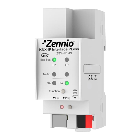
- Page 1 Zennio KNX-IP Router PLess Zennio KNX-IP Interface PLess Router and Interface KNX to IP ZSY-IPR-PL ZSY-IPI-PL Application Program version Zennio KNX-IP Router PLess: [1.1] Application Program version Zennio KNX-IP Interface PLess: [1.0] User Manual version: [1.1]_b www.zennio.com...
-
Page 2: Table Of Contents
Zennio KNX-IP Router / Interface PLess CONTENTS Contents ..........................2 Document Updates ........................ 3 Introduction ........................4 Zennio KNX-IP Router/Interface PLess ..............4 Installation ......................6 Using the Device as a Programmer ............... 7 1.3.1 Parallel Downloads .................... 7 1.3.2 Limitations ......................8 Description ........................ -
Page 3: Document Updates
The IP address of the tunnelling addresses in use is displayed. [1.1]_b Changes in the document: • Minor corrections Changes in the Zennio KNX-IP Router PLess application program: [1.1]_a • Character restriction for “Host Name” parameter. • Internal code optimisation. -
Page 4: Introduction
The main differences between the two devices are: Zennio KNX-IP Interface PLess: simple KNX to IP interface solution. Zennio KNX-IP Router PLess: can be used as line or area coupler to provide data connection between the upper KNXnet/IP line and the lower KNX twisted-pair bus line. - Page 5 Zennio KNX-IP Router / Interface PLess High capacity buffer for the reception of telegrams from the Ethernet network. Web interface to display the device settings, to switch to the programming mode and for firmware updates. 7 lighting indicators (LEDs): two bus state indicators per line (with detection of abnormal situations: excessive bus load, message retransmissions, etc.),...
-
Page 6: Installation
After the connection, the device can be conveniently mounted on the DIN rail by the usual procedure The programming button (10) shown in Figure 2 may be pressed to set Zennio KNX-IP Router PLess in programming mode. After a short press, the programming LED (9) will light in red. -
Page 7: Using The Device As A Programmer
Zennio KNX-IP Router / Interface PLess 1.3 USING THE DEVICE AS A PROGRAMMER Zennio KNX-IP Router PLess and Zennio KNX-IP Interface PLess can be used in ETS as a programming interface. In addition to an IP address, they must be assigned a KNX individual address for this purpose. -
Page 8: Limitations
ETS is not the one configured for the line but the general one. 1.3.2 LIMITATIONS It is important to note that Zennio KNX-IP Router PLess and Zennio KNX-IP Interface PLess, when being used as programmer, do not allow bus monitoring (the ETS bus monitor will not be available). -
Page 9: Description
Note: this functionality does not apply to Zennio KNX-IP Interface PLess. Zennio KNX-IP Router PLess can be used as a line coupler (for coupling both a line to a mainline) or as an area coupler (for coupling a main line to an area line, also referred to as backbone line). - Page 10 3.2.1 Figure 5 Line Coupling On the other hand, Zennio KNX-IP Router PLess can be incorporated to the ETS project topology as any other device. This step is not compulsory if the default configuration meets the requirements of the integrator. However, should they require modifying any parameters or filter table the device must be assigned a physical address prior to downloading the new parameterisation.
-
Page 11: Telegram Filtering
Zennio KNX-IP Router / Interface PLess 2.3 TELEGRAM FILTERING Note: this functionality does not apply to Zennio KNX-IP Interface PLess. Zennio KNX-IP Router PLess provides two complementary filter types: Group address filtering: ETS automatically generates a group address table for the project loaded. This table is transferred to the line coupler during complete ETS downloads over it. - Page 12 Zennio KNX-IP Router / Interface PLess Physical address filtering: when the device receives a telegram where the destination address is a physical/individual address (for example, during downloads), it will compare such address with its own physical address (no particular filter table is required for physical address filtering, but a simple comparison).
-
Page 13: Led Indicators
Zennio KNX-IP Router / Interface PLess 2.4 LED INDICATORS Zennio KNX-IP Router / Interface PLess incorporates seven LED lights on the top of the device that make it easy to monitor the status of the buses and to detect typical communication problems, as detailed next. - Page 14 ➢ ON (red and green = orange): all group addresses routed (filtering disabled). ➢ ON (red): all group addresses blocked. Note: these LEDs are non-functional in Zennio KNX-IP Interface PLess. Physical Address (PA) Filter Status LED: shows the current configuration of the individual address routing: ➢...
- Page 15 ➢ ON (green and orange = yellow): all physical addresses routed (filtering disabled). ➢ ON (orange): all physical addresses blocked. Notes: ➢ These LEDs are non-functional in Zennio KNX-IP Interface PLess. ➢ Please be careful not to confuse yellow and orange. Programming LED: ➢ OFF = normal operation.
-
Page 16: Manual Function Button
Zennio KNX-IP Router / Interface PLess 2.5 MANUAL FUNCTION BUTTON Zennio KNX-IP Router / Interface PLess features an additional pushbutton on the top cover, next to the status LEDs (see (5) in Figure 2), which permits: Activating the Manual Operation Mode (see section 2.5.1), only in Zennio KNX-IP Router PLess. -
Page 17: Hard Reset To Factory Defaults
Zennio KNX-IP Router / Interface PLess 2.5.2 HARD RESET TO FACTORY DEFAULTS The manual function button permits performing a hard reset of the device, which will set it back to the factory default state, including the initial individual address. The... -
Page 18: Web Interface
LAN segment than the PC. On the other hand, the MAC address must be printed on the cover of the device. Note: Zennio KNX-IP Router PLess allows using port 80 instead of 8080 by enabling it in parameters. In such case, it can be omitted from the access URL. -
Page 19: Knx
It can be configured in ETS. Serial number: shows the internal serial number of the device. KNX Busload (only in Zennio KNX-IP Router PLess): shows a graph that reflects the KNX bus load in the past 60 minutes; see Figure 10. The red curve represents the local maximum while the green one indicates the local average load on the KNX bus. - Page 20 Figure 10 Web interface (KNX bus load) 2.6.2.1 ADDICIONAL INDIVIDUAL ADDRESSES (TUNNELING ADDRESSES) Zennio KNX-IP Router / Interface PLess requires a specific individual address when acting as a programming interface (tunneling) other than the address of the device itself. Up to four simultaneous connections are possible, which implies that up to four different individual addresses must be configured.
- Page 21 Zennio KNX-IP Router / Interface PLess Figure 12 Configuration of the first tunneling address in ETS4. Figure 13 Configuration of the first tunneling address in ETS5. http://www.zennio.com Technical Support: http://support.zennio.com...
-
Page 22: Firmware Update
Zennio KNX-IP Router / Interface PLess 2.6.3 FIRMWARE UPDATE The “Update” section of the web interface permits updating the internal firmware of the device whenever Zennio releases firmware version (through http://www.zennio.com website) by following these steps (please see Figure 14): Authorise the update: ➢... - Page 23 Zennio KNX-IP Router / Interface PLess During the Boot mode’ the TP line status LED indicator blinks in green. Notes: The Boot mode can be alternatively accessed by disconnecting the power supply and re-connecting it while pressing the Programming or the Manual Function buttons, or both together.
-
Page 24: Ets Parameterisation
When intending to use the device as a programming interface, it will be necessary to access the ETS settings and select the desired interface In the case of Zennio KNX-IP Router PLess, note that, depending on where the device is placed, the upper levels of the topology need to be configured as KNXnet / The backbone line, in case of working as an area coupler. - Page 25 Finally, the configuration process begins by entering the Parameters tab of the device. The following sections provide a detailed explanation about each of the different parameters of the device. Note: Zennio KNX-IP Router / Interface PLess does not require any communication objects. http://www.zennio.com Technical Support: http://support.zennio.com...
-
Page 26: General
Zennio KNX-IP Router / Interface PLess 3.1 GENERAL When entering the parameter edition of Zennio KNX-IP Router / Interface PLess for the first time, a window similar to Figure 18 will be shown. Figure 18 General tab. As shown in Figure 18, this screen contains the following parameters: Host Name: string of up to 30 characters to easily identify the device in ETS or from a KNXnet/IP system. -
Page 27: Ip Configuration
3.2 IP CONFIGURATION Figure 19 IP Configuration tab Zennio KNX-IP Router / Interface PLess is provided with the DHCP protocol [Do Not Use / Use] enabled by default, and therefore can gain an IP address automatically as long as a DHCP server is available in the local network. From ETS, it is possible to disable the use of the DHCP and manually set an IP address for the device, as well as the subnet mask, the IP address of the network gateway and that of the DNS server. -
Page 28: Knx Multicast Address
LED lighting in red colour. To exit this status, it is necessary to disconnect the Ethernet cable and restore the factory defaults (section 2.5.2). In the particular case of Zennio KNX-IP Router PLess, an option is also provided to select the desired access port to the web interface [80 / 8080]. -
Page 29: Main Line
Zennio KNX-IP Router / Interface PLess 3.4 MAIN LINE Note: this functionality does not apply to Zennio KNX-IP Interface PLess. Figure 21 Main Line (IP) configuration tab. This screen permits parameterising the behaviour of Zennio KNX-IP Router PLess regarding the telegrams received from the main line (Ethernet). -
Page 30: Line
“Transmit All”. 3.5 LINE Note: this functionality does not apply to Zennio KNX-IP Interface PLess. This screen permits parameterising the behaviour of Zennio KNX-IP Router PLess regarding the telegrams received from the KNX line. - Page 31 Zennio KNX-IP Router / Interface PLess Figure 22 KNX line (TP) configuration tab. The following parameters are specific for the line (they are not available for the main line): Physical Addresses: Repetition if Errors on Line: sets the desired reaction upon transmission errors in the line (e.g.: busy receiver, acknowledgement...
- Page 32 Configuration from Line [Enable/Disable]: enables or disables performing ETS downloads over the Zennio KNX-IP Router from the line. If disabled, programming this device from ETS will only be possible via IP.
- Page 33 Join and send us your inquiries about Zennio devices: http://support.zennio.com Zennio Avance y Tecnología S.L. C/ Río Jarama, 132. Nave P-8.11 45007 Toledo (Spain). Tel. +34 925 232 002 www.zennio.com info@zennio.com...