Panasonic VariCam LT Operating Manual
Hide thumbs
Also See for VariCam LT:
- Operating manual (182 pages) ,
- White paper (22 pages) ,
- Operating manual (2 pages)

Related Manuals for Panasonic VariCam LT


Summary of Contents for Panasonic VariCam LT
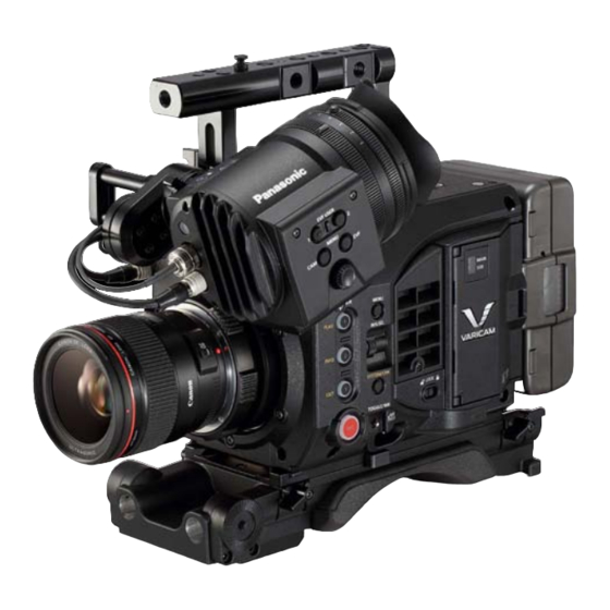
- Page 1 Operating Guide Version 6.0 * The photograph is an example of a system. W0316HM6028 -YI VQT5M58A-6(E)
- Page 2 Electronic HD color view finder that can be used is referred to as “AU-VCVF10G”. Refer to the support desk at the following website for the latest information regarding the electric HD color view finder. http://pro-av.panasonic.net/ r Combining the products f This document describes with assumption to use in the following combination of products.
-
Page 3: Table Of Contents
Contents Contents Selecting the resolution, codec, and video format for Chapter 1 Overview recording Before using the camera When [FREQUENCY] is set to [23.98p] Accessories/options When [FREQUENCY] is set to [24.00p] When [FREQUENCY] is set to [25.00p] Camera When [FREQUENCY] is set to [29.97p] Electronic HD color view finder (optional: AU-VCVF10G) When [FREQUENCY] is set to [50.00p] Shoulder mount module (optional: AU-VSHL2G) - Page 4 Contents Convenient shooting functions Wired LAN settings Checking network setting Zebra patterns display Changing network setting Displaying the center marker Displaying the safety zone marker Connecting the remote operation panel Displaying frame marker Setting for connection with remote operation panel Focus assist function Using the FTP client function False color mode...
-
Page 5: Chapter 1 Overview
Overview Chapter 1 Before using the camera, read this chapter. -
Page 6: Before Using The Camera
7 This product includes software licensed under MOZILLA PUBLIC LICENSE. For details on these descriptions (originally provided in English) and how to obtain the source code, visit the following website: http://pro-av.panasonic.net/ We do not accept inquiries about the details of the source code obtained by the customer. -
Page 7: Accessories/Options
Chapter 1 Overview — Accessories/options Accessories/options Camera f Mount cap (already attached to the camera module) f Control panel f Control panel mounting part f Glass for IR recording f Control panel mounting part clamping screw (4 pcs.) Electronic HD color view finder (optional: AU-VCVF10G) f Slider unit f Slider unit mounting screw (2 pcs.) f BNC cable... -
Page 8: Use Of The Camera On A System
Refer to the support desk at the following website for the latest information regarding the electric HD color view finder. http://pro-av.panasonic.net/ Refer to the support desk at the following website for the latest information regarding the lens that can be used. -
Page 9: Chapter 2 Description Of Parts
Description of Parts Chapter 2 This chapter describes the names, functions, and operations of parts on the camera. -
Page 10: Camera
Chapter 2 Description of Parts — Camera Camera Left side 11 12 14 15 16 17 18 19 1 Accessory mounting holes For attaching accessories. f Mounting hole size - 3/8-16 UNC 2 Handle 3 Lens flange back adjustment hole Used when adjusting the lens flange back. -
Page 11: Right Side
Chapter 2 Description of Parts — Camera 16 Speaker EE audio can be monitored during recording while playback audio can be monitored during playback. The alarm is output in sync with flashing/lighting of the warning indicator. Audio from the speaker automatically is turned off when headphones are connected to the <PHONES> terminal. 17 Card slot cover open/close lever Opens the card slot cover. -
Page 12: Front
Chapter 2 Description of Parts — Camera 13 <VF SDI> terminal An output terminal of 3G/HD SDI for connecting the viewfinder. Use the BNC cable supplied with the viewfinder or the double-shielded cable equivalent to 5C-FB when connecting a cable to this terminal. 14 <DC OUT>... -
Page 13: Top
Chapter 2 Description of Parts — Camera 3 Battery contact terminals Contact terminals for the battery. 4 <INPUT 1/2> terminal Terminal for connecting a microphone. 5 <INPUT 3>/<INPUT 4> terminal Connect the audio equipment or the microphone. 6 <DC OUT/RS> terminal Terminal for DC 12 V output and REC trigger input. -
Page 14: Electronic Hd Color View Finder
Chapter 2 Description of Parts — Electronic HD color view finder Electronic HD color view finder Left side 1 <EVF USER 1>/<EVF USER 2> buttons User-selected functions can be assigned to each button. Pressing a button performs the assigned function. Functions are set on the viewfinder menu. -
Page 15: Rear
Chapter 2 Description of Parts — Electronic HD color view finder DC IN Data communication (from the viewfinder to the camera body) Data communication (from the camera body to the viewfinder) +12 V Cable connector HR10A-7R-4SC (73) (Hirose Electric Co.) Rear 1 Eye sensor Screen is displayed on the viewfinder when an eye is brought close. -
Page 16: Shoulder Mount Module
Chapter 2 Description of Parts — Shoulder mount module Shoulder mount module Left side 1 Support rod lock knob Secures the rod in place. 2 Accessory attachment (rosette) For attaching accessories. f Mounting screw size - M6 (screw length 9 mm or shorter) 3 Stopper Pressed when removing the slide rail from the shoulder mount module. -
Page 17: Grip Module
Chapter 2 Description of Parts — Grip module Grip module Left side 1 <USER GRIP2> button The function that user has selected can be assigned. Pressing a button performs the assigned function. 2 Arm mounting section For attaching an arm. 1 <REC>... -
Page 18: Pl Lens Mount Module
Chapter 2 Description of Parts — PL lens mount module PL lens mount module Left side 1 Mounting screw The screw to fix the PL lens mount module to the camera. 2 Mount fixing ring Fixes the PL lens mount module to the camera. 3 Tightening hole The mount fixing ring can be tightened using an Allen wrench. -
Page 19: Chapter 3 Preparation
Preparation Chapter 3 Attach the module following the procedure in this chapter before using. The mounting of accessories is also described in this chapter. -
Page 20: Mounting The Module
Chapter 3 Preparation — Mounting the module Mounting the module Mounting the control panel The control panel is used by connecting the control panel cable to the <CONTROL PANEL> terminal at the rear of the camera. Normal operation may not be possible when the control panel is mounted or removed while the power is turned on. Set the power switch to <... -
Page 21: Mounting The Electronic Hd Color View Finder
Chapter 3 Preparation — Mounting the module Mounting the electronic HD color view finder Lock Release Fig. 2 Fig. 1 Attach the slider unit to the viewfinder mounting holes on top of the camera using the two supplied screws. (Fig. 1) Slide the viewfinder plate from above into the slider unit. -
Page 22: Mounting The Shoulder Mount Module
Chapter 3 Preparation — Mounting the module Mounting the shoulder mount module Slide rail lock knob Lock Release Stopper Fig. 1 Fig. 2 Disassembling Mounting Stopper opening Fig. 3 Fig. 4 Release the fixing by turning the slide rail lock knob anticlockwise. (Fig. 1) The angle of the slide rail lock knob can be changed by turning while pulling forward. -
Page 23: Mounting The Grip Module
Chapter 3 Preparation — Mounting the module Mounting the grip module Grip arm Grip Fig. 1 Fig. 2 <LENS/GRIP> terminal Fig. 3 Fig. 4 Attach the grip arm to the grip. (Fig. 1) Attach the grip arm to the accessory attachment (rosette) on the shoulder mount module. (Fig. 2) Connect the cable to the <LENS/GRIP>... -
Page 24: Attaching And Removing Accessories
Chapter 3 Preparation — Attaching and removing accessories Attaching and removing accessories Eye cup/eye piece filter The eye cup and eye piece filter can be removed. Always use the camera with these attached. a: Eye cup b: Eye piece filter Attaching a tripod When mounting the camera on a tripod, use the optional tripod adaptor (SHAN-TM700). -
Page 25: Rain Cover
Chapter 3 Preparation — Attaching and removing accessories NOTE t If the tripod adaptor pin does not return to its original position after the camera has been removed, hold the red lever down and move the black lever in the direction of the arrow again, in order to return the pin to its original position. The camera cannot be mounted if the pin remains in the center. -
Page 26: Power Supply
Chapter 3 Preparation — Power supply Power supply A battery or an external DC power supply can be used as the power supply. Using batteries Connection of the following batteries to the camera has been verified. r Anton/Bauer batteries HYTRON140 DIONIC HC/DIONIC HCX/DIONIC HD r IDX batteries ENDURA HL9... -
Page 27: Using The External Dc Power Supply
If the +12 V power supply is mistakenly connected to the GND terminal, it may cause fire or malfunction. DC IN +12 V Panasonic parts No.:K1AA104H0037 Manufacturer Parts No.: HA16RA-4P(77) (Hirose Electric Co.) NOTE t When both the battery and the external DC power supply are connected, the power supply from the external DC power supply has priority. The battery may be removed while using the external DC power supply. -
Page 28: Switching Between External Dc Power Supply And Battery Power Supply
Chapter 3 Preparation — Power supply Switching between external DC power supply and battery power supply Status for both the battery power supply and the external DC power supply are monitored within the camera. Status of each power supply can be confirmed in the control panel and the indicator. -
Page 29: Mounting And Adjusting The Lens
Chapter 3 Preparation — Mounting and adjusting the lens Mounting and adjusting the lens EF lens Mounting the lens Lens fixing ring Marks Mount cap Fig. 1 Fig. 2 Fig. 3 Turn the lens fixing ring and remove the mount cap. (Fig. 1) Align the mark (red circle) on the lens mount with the mark (red circle) on the lens, and mount the lens. -
Page 30: Pl Lens
Chapter 3 Preparation — Mounting and adjusting the lens PL lens The PL lens can be used by replacing the lens mount. Replacing the lens mount EF mount Tightening hole Mount fixing ring (Hexagon hole) Mounting screw (Round hole, 2 locations) Mounting Mounting screw... -
Page 31: Lens Flange Back Adjustment
Chapter 3 Preparation — Mounting and adjusting the lens Mounting the lens Lens fixing ring Mount cap Fig. 1 Fig. 2 Cable clamp <LENS/GRIP> terminal Fig. 3 Fig. 4 Turn the lens fixing ring and remove the mount cap. (Fig. 1) Align the convex portion at the upper right of the lens mount with the concave portion at the lens mount to mount the lens. -
Page 32: Connecting To The Dc Output Terminal
Chapter 3 Preparation — Connecting to the DC output terminal Connecting to the DC output terminal Connecting the <DC OUT/RS> terminal to the external recording start/stop switch The <DC OUT/RS> terminal can supply 1.0 A current. Recording start/stop can be controlled by connecting an external switch to this terminal. An LED connected to this terminal can also be used as a tally lamp. -
Page 33: Charging The Built-In Battery
Chapter 3 Preparation — Charging the built-in battery Charging the built-in battery The date/time set in the camera is maintained by the built-in battery. The built-in battery may be consumed when the power of the camera is not turned on for approximately a half year. The built-in battery is exhausted when [BACKUP BATT EMPTY] is displayed in the viewfinder for approximately five seconds when the power switch is set to <... -
Page 34: Setting The Date/Time Of The Internal Clock
Chapter 3 Preparation — Setting the date/time of the internal clock Setting the date/time of the internal clock The date/time and time zone are recorded as metadata in the content (clip) while shooting. The date/time metadata will affect the playback order by the thumbnail. -
Page 35: Inspections Before Shooting
Chapter 3 Preparation — Inspections before shooting Inspections before shooting Before shooting, perform the following inspections to ensure that the system operates properly. Confirm that the assembled modules and the handles are fixed securely. Insert expressP2 memory card in the main slot, and Class10 or higher SDXC/SDHC memory card in the sub slot, and close the slot cover. -
Page 36: Video Recording And Color Grading
Video Recording and Color Chapter 4 Grading This chapter describes the video combinations that can be recorded and the color grading (in-camera color grading) that can be performed using the camera. -
Page 37: Dual-Recording
Chapter 4 Video Recording and Color Grading — Dual-recording Dual-recording The camera has two built-in recorders. Main slot Sub slot r Main recorder Card slot P2 card slot (main slot) Compatible memory cards expressP2 memory card P2 memory card (with some restrictions) f The P2 memory card cannot be used with the 4K format, ProRes format, [AVC-Intra2K 444] format, [AVC-Intra444] format, or when the variable frame rate function is enabled. -
Page 38: File Name Style
Chapter 4 Video Recording and Color Grading — Dual-recording File name style The file name style for recorded clips can be set in [MENU] → [REC SETTINGS] → [FILE NAME STYLE]. [CINE] Start recording Stop recording Example: [AVC-Intra4K 422] [MAIN CODEC] CLIP1:A001C002_160401_I40B The file name is the same Example: [AVC-Proxy G6]... - Page 39 Chapter 4 Video Recording and Color Grading — Dual-recording [P2] Start recording Stop recording Example: [AVC-Intra4K 422] CLIP1: 451QM200 CLIP2: 451QM201 [MAIN CODEC] Example: [AVC-Proxy G6] (The recording media is SDHC) [PROXY CODEC] CLIP1: 451QM200 CLIP2: 451QM201 The video of the junction point and the file name are the same. Fig.
-
Page 40: Selecting The Resolution, Codec, And Video Format For Recording
Chapter 4 Video Recording and Color Grading — Selecting the resolution, codec, and video format for recording Selecting the resolution, codec, and video format for recording You can select the recording resolution, recording codec, and recording frame rate. f [FREQUENCY]: System frequency f [SDI RAW]: RAW output format f [MAIN PIXEL]: Resolution f [MAIN CODEC]: Recording format... - Page 41 Chapter 4 Video Recording and Color Grading — Selecting the resolution, codec, and video format for recording [MAIN PIXEL] [MAIN CODEC] [VFR PROXY REC] [ProRes 422] 1fps - 60fps [PROXY SLOT]: [MAIN & SUB]/[MAIN] f [VFR up to 60p]* [PROXY SLOT]: [SUB] f [VFR up to 60p]* f [NORMAL+Audio]* : 23.98fps...
- Page 42 Chapter 4 Video Recording and Color Grading — Selecting the resolution, codec, and video format for recording When [SDI RAW] is set to [4K/12bit] [HIGH SPEED] cannot be set. [MAIN PIXEL] [MAIN CODEC] [VFR PROXY REC] [AVC-Intra2K 444] — [2048×1080] ([NORMAL+Audio]* : 23.98fps) * [OFF]...
- Page 43 Chapter 4 Video Recording and Color Grading — Selecting the resolution, codec, and video format for recording When [SDI RAW] is set to [UHD/12bit] [HIGH SPEED] cannot be set. [MAIN PIXEL] [MAIN CODEC] [VFR PROXY REC] [AVC-Intra444] — [1920×1080] ([NORMAL+Audio]* : 23.98fps) * [OFF] —...
-
Page 44: When [Frequency] Is Set To [24.00P]
Chapter 4 Video Recording and Color Grading — Selecting the resolution, codec, and video format for recording Cannot be selected when [VFR] is set to [ON]. The [VFR PROXY REC] item is not displayed in the menu. When [SDI RAW] is set to [2K/10bit] [MAIN PIXEL] will be set to [2048×1080 CROP]. - Page 45 Chapter 4 Video Recording and Color Grading — Selecting the resolution, codec, and video format for recording [MAIN PIXEL] [MAIN CODEC] [VFR PROXY REC] [ProRes 422 HQ] 1fps - 60fps [PROXY SLOT]: [MAIN & SUB]/[MAIN] f [VFR up to 60p]* [PROXY SLOT]: [SUB] f [VFR up to 60p]* f [NORMAL+Audio]*...
-
Page 46: When [Frequency] Is Set To [25.00P]
Chapter 4 Video Recording and Color Grading — Selecting the resolution, codec, and video format for recording [MAIN PIXEL] [MAIN CODEC] [VFR PROXY REC] [ProRes 422] 1fps - 60fps [PROXY SLOT]: [MAIN & SUB]/[MAIN] f [VFR up to 60p]* [PROXY SLOT]: [SUB] f [VFR up to 60p]* f [NORMAL+Audio]* : 24.00fps... - Page 47 Chapter 4 Video Recording and Color Grading — Selecting the resolution, codec, and video format for recording [MAIN PIXEL] [MAIN CODEC] [VFR PROXY REC] [ProRes 4444] 1fps - 25.00fps [PROXY SLOT]: [MAIN & SUB]/[MAIN] f [VFR up to 50p]* [PROXY SLOT]: [SUB] f [VFR up to 50p]* f [NORMAL+Audio]* : 25.00fps...
- Page 48 Chapter 4 Video Recording and Color Grading — Selecting the resolution, codec, and video format for recording The frame rate will be the same as [MAIN CODEC]. Audio is recorded. The [VFR PROXY REC] item is not displayed in the menu. Cannot be selected when [VFR] is set to [ON].
- Page 49 Chapter 4 Video Recording and Color Grading — Selecting the resolution, codec, and video format for recording When [SDI RAW] is set to [UHD/12bit] [HIGH SPEED] cannot be set. [MAIN PIXEL] [MAIN CODEC] [VFR PROXY REC] [AVC-Intra444] — [1920×1080] ([NORMAL+Audio]* : 25.00fps) * [OFF] —...
-
Page 50: When [Frequency] Is Set To [29.97P]
Chapter 4 Video Recording and Color Grading — Selecting the resolution, codec, and video format for recording Cannot be selected when [VFR] is set to [ON]. The [VFR PROXY REC] item is not displayed in the menu. When [SDI RAW] is set to [2K/10bit] [MAIN PIXEL] will be set to [2048×1080 CROP]. - Page 51 Chapter 4 Video Recording and Color Grading — Selecting the resolution, codec, and video format for recording [MAIN PIXEL] [MAIN CODEC] [VFR PROXY REC] [ProRes 4444 XQ] 1fps - 29.97fps [PROXY SLOT]: [MAIN & SUB]/[MAIN] f [VFR up to 60p]* [PROXY SLOT]: [SUB] f [VFR up to 60p]* f [NORMAL+Audio]*...
- Page 52 Chapter 4 Video Recording and Color Grading — Selecting the resolution, codec, and video format for recording [MAIN PIXEL] [MAIN CODEC] [VFR PROXY REC] [AVC-Intra100] 1fps - 120fps [PROXY SLOT]: [SUB] f ([NORMAL+Audio]* : 29.97fps)* [AVC-LongG50] — [PROXY SLOT]: [SUB] f ([NORMAL+Audio]* : 29.97fps)* [AVC-LongG25]...
- Page 53 Chapter 4 Video Recording and Color Grading — Selecting the resolution, codec, and video format for recording [MAIN PIXEL] [MAIN CODEC] [VFR PROXY REC] [OFF] 1fps - 60fps [PROXY SLOT]: [MAIN & SUB]/[MAIN] f [VFR up to 60p]* [PROXY SLOT]: [SUB] f [VFR up to 60p]* f [NORMAL+Audio]* : 29.97fps...
-
Page 54: When [Frequency] Is Set To [50.00P]
Chapter 4 Video Recording and Color Grading — Selecting the resolution, codec, and video format for recording [MAIN PIXEL] [MAIN CODEC] [VFR PROXY REC] [ProRes 422 LT] 1fps - 60fps [PROXY SLOT]: [MAIN & SUB]/[MAIN] f [VFR up to 60p]* [PROXY SLOT]: [SUB] f [VFR up to 60p]* f [NORMAL+Audio]*... - Page 55 Chapter 4 Video Recording and Color Grading — Selecting the resolution, codec, and video format for recording [MAIN PIXEL] [MAIN CODEC] [VFR PROXY REC] [2048×1080] [AVC-Intra2K 422] 1fps - 50fps [PROXY SLOT]: [MAIN & SUB]/[MAIN] f [VFR up to 50p]* [PROXY SLOT]: [SUB] f [VFR up to 50p]* f [NORMAL+Audio]*...
- Page 56 Chapter 4 Video Recording and Color Grading — Selecting the resolution, codec, and video format for recording When [SDI RAW] is set to [4K/10bit] [HIGH SPEED] cannot be set. [MAIN PIXEL] [MAIN CODEC] [VFR PROXY REC] [AVC-Intra4K-LT] 1fps - 50fps [PROXY SLOT]: [MAIN &...
-
Page 57: When [Frequency] Is Set To [59.94P]
Chapter 4 Video Recording and Color Grading — Selecting the resolution, codec, and video format for recording [MAIN PIXEL] [MAIN CODEC] [VFR PROXY REC] [ProRes 422] 1fps - 50fps [PROXY SLOT]: [MAIN & SUB]/[MAIN] f [VFR up to 50p]* [PROXY SLOT]: [SUB] f [VFR up to 50p]* f [NORMAL+Audio]* : 50fps... - Page 58 Chapter 4 Video Recording and Color Grading — Selecting the resolution, codec, and video format for recording [MAIN PIXEL] [MAIN CODEC] [VFR PROXY REC] [3840×2160] [AVC-Intra4K-LT] 1fps - 59.94fps [PROXY SLOT]: [MAIN & SUB]/[MAIN] f [VFR up to 60p]* [PROXY SLOT]: [SUB] f [VFR up to 60p]* f [NORMAL+Audio]* : 59.94fps...
- Page 59 Chapter 4 Video Recording and Color Grading — Selecting the resolution, codec, and video format for recording When [SDI RAW] is set to [4K/10bit] [HIGH SPEED] cannot be set. [MAIN PIXEL] [MAIN CODEC] [VFR PROXY REC] [AVC-Intra4K-LT] 1fps - 59.94fps [PROXY SLOT]: [MAIN &...
- Page 60 Chapter 4 Video Recording and Color Grading — Selecting the resolution, codec, and video format for recording When [SDI RAW] is set to [UHD/10bit] [HIGH SPEED] cannot be set. [MAIN PIXEL] [MAIN CODEC] [VFR PROXY REC] [AVC-Intra4K-LT] 1fps - 59.94fps [PROXY SLOT]: [MAIN &...
-
Page 61: When [Frequency] Is Set To [50.00I]
Chapter 4 Video Recording and Color Grading — Selecting the resolution, codec, and video format for recording [MAIN CODEC] [HIGH SPEED] [VFR PROXY REC] [AVC-Intra100] — 1fps - 120fps [PROXY SLOT]: [SUB] f [NORMAL+Audio]* : 59.94fps [AVC-LongG50] — — [PROXY SLOT]: [SUB] f ([NORMAL+Audio]* : 59.94fps)* [AVC-LongG25]... -
Page 62: Color Setting
Chapter 4 Video Recording and Color Grading — Color setting Color setting Applies the LUT to the recording image and monitor image. It also sets the mode such as V-Log or V-709. COLOR screen setting The following settings can be set in the COLOR screen. These can also be set from [MENU]. f [MAIN COLOR]: Color setting for main recording f [Grading SEL]: Grading function setting f [PROXY COLOR]: Color setting for proxy recording... -
Page 63: [Main Color] Setting
Chapter 4 Video Recording and Color Grading — Color setting [MAIN COLOR] setting Sets the video (color of entire camera system) that is recorded in the main slot. Fig. 1 Fig. 2 [MAIN COLOR] setting is displayed in the status display area at the center of the COLOR screen. [MAIN COLOR] is the item to be set as the master color space for that project only once before the production is started. -
Page 64: [3D Lut] Setting
Chapter 4 Video Recording and Color Grading — Color setting [3D LUT] setting Selects the 3D LUT function. 3D LUT function will function in following cases. f When [MAIN COLOR] is set to [V-Log], and [Grading SEL] is set to anything other than [OFF]. f When [MAIN COLOR] is set to [SHADING], and [GAMMA SELECT] is set to [V-Log]. -
Page 65: [Cdl] Setting
Chapter 4 Video Recording and Color Grading — Color setting [CDL] setting Selects the CDL function. The CDL function is enabled when [MAIN COLOR] is set to [V-Log] and [Grading SEL] is set to [Internal] or [External App]. r [CDL] top screen ([Grading SEL] = [Internal]) r [CDL] top screen ([Grading SEL] = [External App]) r [Slope] screen ([Offset], [Power]) Various parameters can be adjusted from this screen when [Grading SEL] is set to [Internal]. - Page 66 Chapter 4 Video Recording and Color Grading — Color setting r [Saturation] screen Various parameters can be adjusted from this screen when [Grading SEL] is set to [Internal]. This can be adjusted in 0.01 steps with the control panel operation button. It is reflected to video in real time.
-
Page 67: [Sdi Set]
Chapter 4 Video Recording and Color Grading — Color setting [SDI SET] Sets the color of the video output from the <SDI OUT 1>/<SDI OUT 2>/<VF SDI> terminal. f The item that can be selected is switched every time the control panel operation button is pressed. For the item that can be selected, refer to “Control combinations through settings”... -
Page 68: Image Quality Adjustment
Chapter 4 Video Recording and Color Grading — Image quality adjustment Image quality adjustment When [MENU] → [SYSTEM SETTINGS] → [COLOR SETTINGS] → [MAIN] is set to [SCENE1]/[SCENE2]/[SCENE3]/[SCENE4]/[SCENE5]/[SHADING], the image quality of the video to be recorded can be adjusted in the camera. f The image quality adjustment of the video to be recorded is set in [MENU] →... - Page 69 Chapter 4 Video Recording and Color Grading — Image quality adjustment Following items can be selected in [GAMMA SELECT]. [V-709], [V-406060], [V-452080], [V-452080L], [VIDEO45], [VIDEO50] When [MAIN] is set to [SHADING], [V-Log] or [BC GAMMA] can be selected in [GAMMA] → [GAMMA SELECT]. This can be set only when [GAMMA] →...
- Page 70 Chapter 4 Video Recording and Color Grading — Image quality adjustment [EI] Sets the sensitivity of the video. Dual native ISO The camera is equipped with two [NATIVE ISO], [800ISO] and [5000ISO], which are called as dual native ISO. By installing the sensitivity switching circuit inside the image sensor, a high sensitivity and low noise [5000ISO] is realized. However, the sensitivity will drop 1Stop when [MAIN PIXEL] is set to [2048×1080 CROP]/[1920×1080 CROP] and [MAIN CODEC] is set to [AVC-Intra2K-LT]/[AVC-Intra-LT].
-
Page 71: [White]
Chapter 4 Video Recording and Color Grading — Image quality adjustment [dB] There are two gain modes of [NORMAL] and [HIGH]. The standard sensitivity equivalent to [NATIVE ISO] is set as 0 dB. However, when the gamma curve is set to [VIDEO45]/[VIDEO50]/[BC GAMMA], the dynamic range will be set to 600%, which is less than [V-Log] or other gamma curve. -
Page 72: [Black]
Chapter 4 Video Recording and Color Grading — Image quality adjustment r White pattern f A white object (white cloth or white wall) near the subject may also be used as the white pattern. f Required size of white pattern is as follows. 1/2 or more of the screen width 1/2 or more of the screen height f Keep bright spotlights out of the screen. -
Page 73: [Gamma]
Chapter 4 Video Recording and Color Grading — Image quality adjustment [GAMMA] Set to optimize the tone of video. Selectable items vary depending on the [MENU] → [SYSTEM SETTINGS] → [COLOR SETTINGS] → [MAIN] setting. Output (%) -7.5 Input/Stop [V-Log] [V-709] [V-406060] ([SCENE2]: VARICAM-LOOK) [V-452080] ([SCENE3]: VARICAM-LOOK), [V-452080L]... -
Page 74: [Knee]
Chapter 4 Video Recording and Color Grading — Image quality adjustment f [BC GAMMA]: This is the gamma curve with 600% dynamic range equivalent to the generally used video camera. The gamma factor can be adjusted in the range of [0.150] to [0.750]. -
Page 75: [White Clip]
Chapter 4 Video Recording and Color Grading — Image quality adjustment [WHITE CLIP] This function sets the brightest part of video signals to be not brighter than a certain level. White clip level Output Input Select [ON] in [MENU] → [SCENE FILE SETTINGS] → [WHITE CLIP] → [SW]. Set the level with [LEVEL]. -
Page 76: [Chroma]
Chapter 4 Video Recording and Color Grading — Image quality adjustment r Relationship between color composition of video signal and color difference signal [- I WIDTH] Q axis [- I CENTER] [- Q WIDTH] B-Y/0° [- Q PHASE] I axis Fig. -
Page 77: [Linear Matrix]
Chapter 4 Video Recording and Color Grading — Image quality adjustment [LINEAR MATRIX] Adjusts the linear matrix. Change of color against each axis of the linear matrix is as following figure. (R-G)_P (G-B)_N (B-R)_N (B-R)_P (G-B)_P (R-G)_N (G-R)_N (R-B)_P (B-G)_P (B-G)_N (R-B)_N (G-R)_P... -
Page 78: [Color Correction]
Chapter 4 Video Recording and Color Grading — Image quality adjustment [COLOR CORRECTION] This function sets color saturation and phase. Effect is applied individually against 24 phases of the video. It can be set to individual color hue. (Yl-R)-R (Yl-R) Yl-(Yl-R) (G-Yl)-Yl (G-Yl) -
Page 79: Memory Card
Chapter 4 Video Recording and Color Grading — Memory card Memory card Insert memory card When using the camera for the first time, be sure to set the time data beforehand. (page 34) Insert the P2 card into the main slot and the SD memory card into the sub slot. Main slot Eject button Card slot cover... -
Page 80: To Prevent Unintentional Erasing
Chapter 4 Video Recording and Color Grading — Memory card NOTE t Do not remove the P2 card after inserting it, while it is being accessed, or being detected (card access LED flashing in orange). Otherwise, it may result in a malfunction. t [TURN POWER OFF] is displayed in the viewfinder screen or the center of the control panel or in the warning message area at the top left of each output indicator, and a warning is displayed with the warning lamp, etc., when the P2 card being accessed is removed. -
Page 81: Recording Time Of Memory Card
NOTE t AJ-P2C002SG (2 GB) cards cannot be used. t Refer to our support desk at the following website for the latest information not included in this document. http://pro-av.panasonic.net/ r Sub recorder Sub recording format Recording time when using a 64 GB SD memory... -
Page 82: Formatting A P2 Card
Chapter 4 Video Recording and Color Grading — Memory card t Follow the steps below to use general IT tools such as Microsoft Windows Explorer or Apple Finder to transfer the data to a computer. Be sure to use P2 Viewer Plus to write data back to a P2 card. - Transfer the corresponding CONTENTS folder and LASTCLIP.TXT file together as a set. -
Page 83: Special Recording Functions
Chapter 4 Video Recording and Color Grading — Special recording functions Special recording functions HD cutout high speed recording A high speed recording up to 240p can be performed by cutting out the 2K or HD pixel region of the image sensor when [2048×1080 CROP] or [1920×1080 CROP] is selected in [MENU] →... -
Page 84: Ir Recording
Chapter 4 Video Recording and Color Grading — Special recording functions IR recording The following video representation can be achieved by replacing the IR cut glass (blue glass) mounted in the optical block with a supplied IR recording glass (clear glass). f Night shooting using the IR light f Infrared photography using the IR filter (only IR optical transmittance) Fig. -
Page 85: Pre-Recording
Chapter 4 Video Recording and Color Grading — Special recording functions NOTE t Up to 100 text memos can be recorded to a single clip. Pre-recording This function enables recording of video and audio from a fixed amount of time (approx. three seconds) before the operation to start recording is performed. -
Page 86: One-Shot Recording
Chapter 4 Video Recording and Color Grading — Special recording functions One-shot recording Recording takes place once for the set amount of time. Set [MENU] → [REC SETTINGS] → [REC FUNCTION] → [REC MODE] to [ONE SHOT]. f When [VFR] is set, one-shot recording is not available. Set the following related items from [MENU] →... -
Page 87: Chapter 5 Operation
Operation Chapter 5 This chapter describes the method to change each setting and confirmation method of the setting status. -
Page 88: Control Panel Operation
Chapter 5 Operation — Control panel operation Control panel operation Basic camera operations can be performed using the control panel. a: <HOME> button b: <PLAY> button c: <TC> button d: <INFO> button e: <VIEW> button f: <EXIT> button g: <MENU> button h: Jog dial button i: <LOCK>... - Page 89 Chapter 5 Operation — Control panel operation f Level meter display Displays the level represented by 19 bars. (2 dB increments) f Standard level bar At the −18 dB position or the −20 dB position The setting in [MENU] → [AUDIO SETTINGS] → [AUDIO LEVEL] → [HEADROOM] will be the standard. 6 Warning/error displays : Warning (details are displayed on the time code display in the following cases) f [SYSTEM ERROR !]...
- Page 90 Chapter 5 Operation — Control panel operation 4 Battery and <DC IN> power supply display This is the display when a battery is connected to the battery holder and an AC adaptor ([DC POWER SUPPLY]) is connected to the <DC IN> terminal.
-
Page 91: Home Screen
Chapter 5 Operation — HOME screen HOME screen The Home screen displays the basic camera settings and is used to change those settings. [FPS] Sets the frame rate. Selects from the predefined frame rate. Up to 150 (128 for [25.00p]/[50.00p]) can be registered. Presets can be added/deleted using [ADD]/[DELETE]. - Page 92 Chapter 5 Operation — HOME screen [NORMAL] Sets [GAIN MODE] to [NORMAL]. (When [dB] is set) [HIGH] Sets [GAIN MODE] to [HIGH]. (When [dB] is set) [SYSTEM] Sets the camera’s system. [DAILIES] Sets the data to superimpose on the video to be recorded in the sub recorder. [WATER MARK]: Superimposes the set character string.
-
Page 93: Play Screen
Chapter 5 Operation — PLAY screen PLAY screen The Play screen is the screen for playing recorded videos. You can select clips by turning the jog dial button. Play the clip selected in the middle by pressing the jog dial button. At the end of the clip, the display will return to the list display. -
Page 94: Tc Screen
Chapter 5 Operation — TC screen TC screen The TC screen is the screen for setting the time code. [TC/UB/Dur.] Switches between the HOME screen and status display. [TC]: Time code [UB]: User bits [Dur.]: Duration [FREE/REC RUN] Switches between free run and recording run. This is fixed to recording run when the variable frame rate function is enabled. -
Page 95: Info Screen
Chapter 5 Operation — INFO screen INFO screen The INFO screen displays information about the camera. [DIAGNOSTICS] Displays camera statuses such as warnings. [SWITCHES] The switch information assigned to each USER switch by [MENU] → [SYSTEM SETTINGS] → [USER SWITCHES] is listed. -
Page 96: View Screen
Chapter 5 Operation — VIEW screen VIEW screen Displays video. For status display contents, configure [MENU] → [OUTPUT SETTINGS] → [VF SDI INDICATOR]. – 96 –... -
Page 97: Menu Screen
Chapter 5 Operation — MENU screen MENU screen Displays the [MENU]. (page 134) [MENU] is also displayed in the output from the <SDI OUT 1> terminal and the <SDI OUT 2> terminal depending on the [MENU] → [OUTPUT SETTINGS] → [SDI OUT] → [MENU DISP] setting. –... -
Page 98: Operation Of The Camera Buttons
Chapter 5 Operation — Operation of the camera buttons Operation of the camera buttons Basic camera operation can be performed with the buttons on the camera. There are buttons with different operations when the control panel is connected or not connected. 1 <USER 1>/<PLAY>... - Page 99 Chapter 5 Operation — Operation of the camera buttons r When the control panel is connected f When the <USER 3> button Turns ON/OFF the function selected in [MENU] → [SYSTEM SETTINGS] → [USER SWITCHES] → [USER3]. However, the enable/disable differs depending on the assigned function and its status. f When the <EXT>...
- Page 100 Chapter 5 Operation — Operation of the camera buttons r When the control panel is not connected f When outputting the camera video to the viewfinder connected to the <VF SDI> terminal It will become the dial for controlling the iris of the EF lens. However, this will be the audio level increase/decrease operation when the direct volume control is enabled.
-
Page 101: Chapter 6 Audio Recording
Audio recording Chapter 6 This chapter describes how to prepare and adjust audio recorded at the time of shooting. -
Page 102: Preparing For Audio Input
Chapter 6 Audio recording — Preparing for audio input Preparing for audio input Prepare the camera for connecting audio input devices. When using a stereo microphone Microphones such as the stereo microphone kit AJ-MC900G (optional) can be mounted. Fig. 1 Fig. -
Page 103: Using Audio Devices
Chapter 6 Audio recording — Preparing for audio input Select [INPUT1] in [CH1 IN], and [INPUT2] in [CH2 IN]. To record the stereo microphone audio input of the <INPUT 1/2> terminal to audio channels 3/4, switch to [CH3/4] in [MONITOR SEL], and then select [INPUT1] in [CH3 IN], and [INPUT2] in [CH4 IN]. -
Page 104: Selecting Audio Input And Adjusting Recording Levels
Chapter 6 Audio recording — Selecting audio input and adjusting recording levels Selecting audio input and adjusting recording levels The camera supports independent 4-channel sound recording in all recording formats. Selecting audio input signals Press the <HOME> button to display the HOME screen. From [SYSTEM] →... -
Page 105: Audio Monitor
Chapter 6 Audio recording — Selecting audio input and adjusting recording levels From [SYSTEM] → [AUDIO], set [AUDIO IN]. For [CH3/4], switch to [CH1/2] in [MONITOR SEL]. Select [MANUAL] in [CH1 LEVEL] or [CH2 LEVEL]. If [AUTO] is selected, [A] is displayed on the [AUDIO VOL] screen and manual adjustment is not possible. Select [AUDIO VOL] in [SYSTEM] →... - Page 106 Chapter 6 Audio recording — Selecting audio input and adjusting recording levels Adjust the audio level by turning the <IRIS/SEL> dial button or the <IRIS> dial on the grip module. Switches the channel to operate the volume by pressing the USER button (<USER 1>, <USER 2>, <USER 3>, <USER GRIP1>, <USER GRIP2>) that [AUDIO MONITOR CH] is assigned as necessary.
-
Page 107: Chapter 7 Viewfinder
Viewfinder Chapter 7 This chapter describes the viewfinder screen display and how to make adjustments. -
Page 108: Adjusting And Setting The Viewfinder
Chapter 7 Viewfinder — Adjusting and setting the viewfinder Adjusting and setting the viewfinder The camera’s panel is OLED (organic EL). Positioning your eye near the viewfinder will trigger the eye sensor to automatically display the image. Adjustment method a: Lock lever (left/right position) b: Lock lever (front/back position) c: Visibility adjustment ring d: Zoom ring... -
Page 109: Viewfinder Status Display
Chapter 7 Viewfinder — Viewfinder status display Viewfinder status display In addition to video, the viewfinder displays messages, a center marker, safety zone marker, zebra patterns, and other information that indicate the camera settings and operation status. Lamp display 1 Green tally lamp Lights up in green when green tally signals are received. - Page 110 Chapter 7 Viewfinder — Viewfinder status display [MENU] settings from the viewfinder [MENU] of the camera can be directly set with the viewfinder operation. Press and hold the <CAM MENU> button of the viewfinder for at least two seconds. The camera [MENU] is displayed. [MENU] is also displayed on the control panel of the camera.
- Page 111 Chapter 7 Viewfinder — Viewfinder status display r [USER SW 1]/[USER SW 2] Selects the function assigned to the <EVF USER 1>/<EVF USER 2> button. This is the common setting as the content displayed and set with [MENU] → [OUTPUT SETTINGS] in the camera. Description of settings [CLEAN VIEW]: Switches to display only video or superimposes the display of markers or indicators.
-
Page 112: Convenient Shooting Functions
Chapter 7 Viewfinder — Convenient shooting functions Convenient shooting functions Zebra patterns display The camera can display two types of zebra patterns. The zebra pattern can be set in [MENU] → [OUTPUT SETTINGS] → [VF SDI EI ASSIST]. Item Description of settings [ZEBRA SW] Sets if the zebra signal is superimposed or not to the output from the <VF SDI>... - Page 113 Chapter 7 Viewfinder — Convenient shooting functions Expanded display Set [MENU] → [OUTPUT SETTINGS] → [VF SDI FOCUS ASSIST] → [EXPAND1 SW]/[EXPAND2 SW] to [ON]. f The display mode can be set in [MENU] → [OUTPUT SETTINGS] → [VF SDI FOCUS ASSIST] → [EXPAND MODE]/[- POS1]/[- VALUE1]/[- POS2]/ [- VALUE2].
-
Page 114: False Color Mode
Chapter 7 Viewfinder — Convenient shooting functions False color mode Check the exposure using the false color. Set [MENU] → [OUTPUT SETTINGS] → [VF SDI FOCUS ASSIST] → [FALSE COLOR SW] to [ON]. Image will be displayed with colors sored by luminosity signals. Images of other levels are displayed in black and white. The false color can be displayed through output from the <VF SDI>... -
Page 115: Chapter 8 Output And Screen Display
Output and Screen Display Chapter 8 This chapter describes video output. -
Page 116: Output
Chapter 8 Output and Screen Display — Output Output Output format list f HD (1920×1080) is always output as the output from the <SDI OUT 1>/<SDI OUT 2>/<VF SDI> terminals regardless of the [MENU] → [SYSTEM SETTINGS] → [SYSTEM MODE] → [MAIN PIXEL] settings. It is output in HD letterbox (black band at top and bottom of the output video) when [MAIN PIXEL] is set to [4096×2160] or [2048×1080]. -
Page 117: Screen Status Display
Chapter 8 Output and Screen Display — Screen status display Screen status display Status display (STATUS) This is the status screen displayed in the <SDI OUT 1>, <SDI OUT 2>, and <VF SDI> output, and the control panel (VIEW screen). 1920 x 1080 999min ProRes444/G6... - Page 118 Chapter 8 Output and Screen Display — Screen status display f RAW is displayed in the system pixel display area when [MENU] → [SYSTEM SETTINGS] → [SYSTEM MODE] → [SDI RAW] is set to anything other than [OFF]. f The recording command status against the external RAW recorder is displayed instead of the main slot card recording status when [MENU] → [SYSTEM SETTINGS] →...
-
Page 119: Chapter 9 Other Useful Functions
Other Useful Functions Chapter 9 This chapter describes other useful features such as function buttons, etc. -
Page 120: Getting Position Information Using The Gps
Chapter 9 Other Useful Functions — Getting position information using the GPS Getting position information using the GPS The camera has a built-in GPS. Positioning information can be recorded through GPS. The GPS antenna is built inside the top of the camera. Do not hold the handle or block the upper section of the camera with an obstruction when the GPS function is in use. -
Page 121: Assigning Functions To The User Buttons
Chapter 9 Other Useful Functions — Assigning functions to the USER buttons Assigning functions to the USER buttons Selected function can be assigned to the USER buttons (<USER 1> to <USER 3>, <TOGGLE/WB> (USER4), <USER GRIP1> to <USER GRIP2>) and the control panel operation buttons (USER5 to USER10). - Page 122 Chapter 9 Other Useful Functions — Assigning functions to the USER buttons Item Description [AUDIO MONITOR Switches the audio channel to output to the <PHONES> terminal. Switches the setting of [MENU] → [AUDIO SETTINGS] → [AUDIO OUTPUT] → [MONITOR CH]. Calls the function to adjust the audio input with the <IRIS/SEL>...
-
Page 123: Handling Setting Data
Chapter 9 Other Useful Functions — Handling setting data Handling setting data File structure of the setting data The scene files ([SCENE1] to [SCENE5], and [SHADING]) can be saved in the camera according to the scene file number. The scene file ([SCENE1] to [SCENE5], and [SHADING]) data can be saved as a file in the SD memory card, which can be loaded and used. The setting value that can be saved as a scene file is the content of [MENU] →... -
Page 124: Performing Operations On Sd Memory Cards
- Use of Panasonic SD memory cards and miniSD/microSD cards is recommended. Also, make sure that the format is performed on the camera. - Refer to our support desk at the following website for the latest information not included in this document. - Page 125 Chapter 9 Other Useful Functions — Handling setting data Enter the text to set with the keyboard. Select [OK] with the jog dial button and press the jog dial button. The confirmation screen is displayed. Select [YES] and press the jog dial button. Saving of the file is started.
-
Page 126: Setting The Time Data
Chapter 9 Other Useful Functions — Setting the time data Setting the time data The camera provides time codes, user bits, and date and time (real time) data as time data, and they are recorded in the frame in sync with video. They are also recorded as data for clip metadata files. -
Page 127: Setting The Time Code
Chapter 9 Other Useful Functions — Setting the time data Retention of user bits in memory User bit settings are automatically recorded and are retained even if the power is turned off. Frame rate information The relationship between frame rates, image pull-down, and time codes/user bits is as follows. Verification information on the right-hand six digits REC mark Fixed values... - Page 128 Chapter 9 Other Useful Functions — Setting the time data Example of connections for external locking As shown in the figure, connect both the reference video signal and the reference time code. Reference time code <TC IN/OUT> terminal Reference video signal <GENLOCK IN>...
-
Page 129: Supplying The Time Code Externally
Chapter 9 Other Useful Functions — Setting the time data Supplying the time code externally You can supply the output time codes to an external recording device from the camera by matching the camera videos or the playback videos. Connection example for supplying to external device r When locking external devices to the camera <SDI OUT 1>/<SDI OUT 2>... - Page 130 Chapter 9 Other Useful Functions — Setting the time data NOTE t Sets the <TC IN/OUT> terminal to output or input in [MENU] → [REC SETTINGS] → [TC] → [TC IN/OUT SEL]. t By setting [MENU] → [REC SETTINGS] → [TC] → [TC OUT REF] to [RECORDING] on both cameras, the two cameras will be able to record with the same time code on the video at the same time.
-
Page 131: Connection Through The
Chapter 9 Other Useful Functions — Connection through the <USB DEVICE> terminal Connection through the <USB DEVICE> terminal Connecting to a computer in the USB device mode Connecting to a computer USB cable (optional) Fig. 1 Connect the USB cable to the <USB DEVICE> terminal (device). (Fig. 1) Set the [MENU] →...Terminal -
Page 132: Chapter 10 Menu Operations
Menu Operations Chapter 10 This chapter describes how to operate the camera menus, the structure, and details of the setting menu. -
Page 133: Setting Menu Structure
Chapter 10 Menu Operations — Setting menu structure Setting menu structure Menu configuration The setting menu is configured as follows. [SYSTEM SETTINGS] Sets the system in general. The system frequency, number of recorded pixels, recording format, and recording method are set here. [CAMERA SETTINGS] Sets the basic camera setting. -
Page 134: Setting Menu Display
Chapter 10 Menu Operations — Setting menu display Setting menu display Setting menu basic operations You can change camera settings using the setting menu according to the shooting scene and recording details. Set data are written and saved in the internal memory of the camera. Operate with the control panel. -
Page 135: Menu List
Chapter 10 Menu Operations — Menu list Menu list [SYSTEM SETTINGS] Sets the system in general. Item Description of settings [SYSTEM MODE] [FREQUENCY] Sets the system frequency. The basic system of the camera is determined by five settings of [FREQUENCY]/[SDI RAW]/[MAIN PIXEL]/[MAIN CODEC]/[HIGH SPEED]. - Page 136 Chapter 10 Menu Operations — Menu list Item Description of settings [SDI OUT 1] Sets the output image from the <SDI OUT 1> terminal. Selectable items vary depending on the [MAIN] setting. When [MAIN] is set to [V-Log] and [GRADING] is set to [Internal] or [External App] [V-Log]/[GRADING] When [MAIN] is set to [V-Log] and [GRADING] is set to [SHADING] [BAKED IN]/[V-Log]...
- Page 137 Chapter 10 Menu Operations — Menu list Item Description of settings [SLOPE-B] Sets the value of [SLOPE-B]. [0.50] - [2.00] (0.01 step) f Factory setting: [1.00] [OFFSET-R] Sets the value of [OFFSET-R]. [−0.50] - [0.50] (0.01 step) f Factory setting: [0.00] [OFFSET-G] Sets the value of [OFFSET-G].
- Page 138 Chapter 10 Menu Operations — Menu list Item Description of settings [IMAGE INVERT] [PROXY & SDI OUT] Sets if the video to be recorded in the proxy and the SDI output video is to be inverted. The thumbnail of the clip to be recorded in the main slot is reversed when set to [ON]. (The recorded video is not reversed.) [ON], [OFF] f Factory setting: [OFF]...
- Page 139 Chapter 10 Menu Operations — Menu list Item Description of settings [USER8] Sets the function to be assigned to the control panel operation button. The control panel operation button functions as a USER button. Assign [SIX USER BUTTONS] to the <USER 1> to <USER 3> buttons. [INHIBIT], [EXPAND1], [EXPAND2], [OPEN IRIS F.A.], [IN COLOR F.A.], [SQ.
- Page 140 Chapter 10 Menu Operations — Menu list Item Description of settings [SYS CHECK] Sets if the <SYSTEM CHK> button is to be locked or not with the <LOCK> switch on the camera. [LOCK]: It will be locked. [UNLOCK]: It will not be locked. f Factory setting: [LOCK] [TOGGLE] Sets if the <TOGGLE/WB>...
- Page 141 Chapter 10 Menu Operations — Menu list Item Description of settings [FAN] [FAN SPEED] Select the rotation speed of the fan. [REC AUTO]: The rotation speed is lowered simultaneously with start of recording. However, the fan will rotate in appropriate speed for each by [MAIN CODEC] when it reaches the specified temperature. The fan will rotate at the maximum speed when not recording.
-
Page 142: [Camera Settings]
Chapter 10 Menu Operations — Menu list [CAMERA SETTINGS] Sets the basic camera function. [WHITE]/[BLACK]/[EI] is enabled only when [MENU] → [SYSTEM SETTINGS] → [COLOR SETTINGS] → [MAIN] is set to [V-Log]. Item Description of settings [FPS] [VFR SW] Enables/disables the variable frame rate function. [ON]: Enables the variable frame rate function. - Page 143 Chapter 10 Menu Operations — Menu list Item Description of settings [GAIN SELECT] Sets the value when [dB] is selected. [−12dB], [−10dB], [−8dB], [−6dB], [−4dB], [−2dB], [0dB], [2dB], [4dB], [6dB], [8dB], [10dB], [12dB], [14dB] When [GAMMA] → [GAMMA SELECT] is set to [VIDEO45]/[VIDEO50]/[BC GAMMA]. This will be set to [−6dB], [−4dB], [−2dB], [0dB], [2dB], [4dB], [6dB], [8dB], [10dB], [12dB], [14dB], [16dB], [18dB], or [20dB].
-
Page 144: [Scene File Settings]
Chapter 10 Menu Operations — Menu list [SCENE FILE SETTINGS] Sets the detailed image quality adjustment of the camera video. [WHITE]/[BLACK]/[EI] are enabled only when [MENU] → [SYSTEM SETTINGS] → [COLOR SETTINGS] → [MAIN] is set to anything other than [V-Log]. Item Description of settings [NAME EDIT]... - Page 145 Chapter 10 Menu Operations — Menu list Item Description of settings [800BASE ISO] Sets the value when [800BASE] is selected. [200ISO], [250ISO], [320ISO], [400ISO], [500ISO], [640ISO], [800ISO], [1000ISO], [1250ISO], [1600ISO], [2000ISO], [2500ISO], [3200ISO], [4000ISO], [5000ISO], [6400ISO], [8000ISO], [10000ISO], [12800ISO] This will be [200ISO], [250ISO], [320ISO], [400ISO], [500ISO], [640ISO], [800ISO], [1000ISO], [1250ISO], [1600ISO], [2000ISO], [2500ISO], [3200ISO], [4000ISO], [5000ISO], or [6400ISO] when [MAIN CODEC] is set to [AVC-Intra2K-LT]/[AVC-Intra-LT], and [MAIN PIXEL] is set to [2048×1080 CROP]/[1920×1080 CROP].
- Page 146 Chapter 10 Menu Operations — Menu list Item Description of settings [KNEE] [KNEE SW] Enables/disables knee operation. (page 74) [ON], [OFF] f Factory setting: [OFF] [KNEE MODE] Sets the knee operation mode. [D RANGE]: Determines the dynamic range that can be represented by the [KNEE SLOPE] value. The dynamic range that can be represented does not change even if the [KNEE POINT] value changes.
- Page 147 Chapter 10 Menu Operations — Menu list Item Description of settings [(R-G)_P] Adjusts the linear matrix. [−127] - [127] f Factory setting: [0] [(R-B)_N] Adjusts the linear matrix. [−127] - [127] f Factory setting: [0] [(R-B)_P] Adjusts the linear matrix. [−127] - [127] f Factory setting: [0] [(G-R)_N]...
- Page 148 Chapter 10 Menu Operations — Menu list Item Description of settings [P5(SAT)] Corrects the color saturation between yellow and green. [−63] - [63] f Factory setting: [0] [P5(PHASE)] Corrects the hue between yellow and green. [−63] - [63] f Factory setting: [0] [P6(SAT)] Corrects the color saturation between “between yellow and green”...
-
Page 149: [Rec Settings]
Chapter 10 Menu Operations — Menu list Item Description of settings [P14(SAT)] Corrects the color saturation between blue and magenta. [−63] - [63] f Factory setting: [0] [P14(PHASE)] Corrects the hue between blue and magenta. [−63] - [63] f Factory setting: [0] [P15(SAT)] Corrects the color saturation between “between blue and magenta”... - Page 150 Chapter 10 Menu Operations — Menu list Item Description of settings [TC] [SET TC] Sets the default value of the time code to record. Hour: [00] - [23] Minute: [00] - [59] Second: [00] - [59] Frame: [00] - [23] (for [24p], [23.98p]), [00] - [24] (for [50i], [50p], [25p]), [00] - [29] (for [59.94i], [59.94p], [29.97p]) f Factory setting: [00] (various items) [SET UB]...
- Page 151 Chapter 10 Menu Operations — Menu list Item Description of settings [VOLUME] Sets the volume of the beep sound when starting or stopping the recording. [LOUD], [MEDIUM], [SMALL] f Factory setting: [MEDIUM] [DAILIES PREVIEW] Displays the setting of [WATER MARK]/[FRAME MARK]/[WINDOW BURN] together with the current camera video for five seconds.
-
Page 152: [Audio Settings]
Chapter 10 Menu Operations — Menu list [AUDIO SETTINGS] Sets the audio recording function. Item Description of settings [AUDIO RECORD] Sets if the recording and output of the audio of the camera is to be performed or not. [ON], [OFF] f Factory setting: [ON] [AUDIO INPUT] [INPUT 3 LINE/MIC SEL] Sets the audio input signal from the device connected to the <INPUT 3>... - Page 153 Chapter 10 Menu Operations — Menu list Item Description of settings [CH2 LEVEL] Sets if the recording level adjustment method for audio channel 2 is to be automatic or manual. [AUTO]: Adjust automatically. [MANUAL]: Enables manual adjustment. f Factory setting: [AUTO] [CH3 LEVEL] Sets if the recording level adjustment method for audio channel 3 is to be automatic or manual.
-
Page 154: [Output Settings]
Chapter 10 Menu Operations — Menu list [OUTPUT SETTINGS] Sets the display contents of the output video and output from the <SDI OUT 1>/<SDI OUT 2>/<VF SDI> terminal. Item Description of settings [SDI OUT] [RAW OUTPUT] Sets if the RAW output from the <SDI OUT 1>/<SDI OUT 2> terminal will be dual output (DUAL) or single output (SINGLE). - Page 155 Chapter 10 Menu Operations — Menu list Item Description of settings [VF SDI OUT] [VF SDI OUT FORMAT] Selects the signal to be output from the <VF SDI> terminal. It is output in the HD (1920×1080) format regardless of the [MAIN PIXEL] setting. The items that can be set differ depending on the settings of [FREQUENCY] and [MAIN CODEC].
- Page 156 Chapter 10 Menu Operations — Menu list Item Description of settings [EI] Switches display/hide of EXPOSURE INDEX. [ON], [OFF] f Factory setting: [ON] [WHITE] Switches display/hide of the color temperature. [ON], [OFF] f Factory setting: [ON] [IRIS] Switches display/hide of the iris value. [ON], [OFF] f Factory setting: [ON] [FOCUS]...
- Page 157 Chapter 10 Menu Operations — Menu list Item Description of settings [SAFETY MARKER] Selects the type of frame for the safety zone marker. [1]: Box [2]: Corners [OFF]: Does not display. f Factory setting: [OFF] [SAFETY AREA] Sets the size of the safety zone marker. [80%] - [100%] (1% step, fixed aspect ratio) f Factory setting: [90%] [FRAME MARK]...
- Page 158 Chapter 10 Menu Operations — Menu list Item Description of settings [FILTER] Displays/hides the optical filter transmittance. [ON], [OFF] f Factory setting: [ON] [EXTENDER] Displays/hides the extender. [ON], [OFF] f Factory setting: [ON] [Y GET] Displays/hides brightness of Y GET. [ON], [OFF] f Factory setting: [ON] [TC]...
- Page 159 Chapter 10 Menu Operations — Menu list Item Description of settings [FRAME SIG] Sets frame marker aspect ratio. [1.33:1], [1.44:1], [1.56:1], [1.78:1], [1.85:1], [2.00:1], [2.201:1], [2.35:1], [2.39:1] f Factory setting: [2.39:1] [FRAME COLOR] Sets the color of the frame marker. [WHITE], [BLACK], [RED], [GREEN], [BLUE], [YELLOW] f Factory setting: [WHITE] [FRAME LEVEL]...
-
Page 160: [File]
Chapter 10 Menu Operations — Menu list Item Description of settings [OPEN IRIS FOCUS [OPEN IRIS FOCUS Switches enable/disable of the open iris focus assist function. ASSIST] [ON], [OFF] f Factory setting: [OFF] [VALUE] Sets the time for the open iris focus is to assist. [10SEC], [30SEC] f Factory setting: [10SEC] [VF SDI EI ASSIST]... -
Page 161: [Peripheral]
Chapter 10 Menu Operations — Menu list [PERIPHERAL] Applies settings related to functions used in conjunction with peripheral devices, such as network and GPS devices. Item Description of settings [GPS] Configures internal GPS settings. [ON]: Activates the GPS operation. Outputs the location information as a signal to the <SDI OUT> terminal and records it as clip metadata. - Page 162 Chapter 10 Menu Operations — Menu list Item Description of settings [SSID INPUT MODE] Sets the setting method of SSID. When [TYPE] in [WIRELESS PROPERTY] is set to [INFRA], this item can be set. [SELECT]: Selects from the access point list. [MANUAL]: For entering the access point manually.
-
Page 163: Initial Value Of The Scene File
Chapter 10 Menu Operations — Initial value of the scene file Initial value of the scene file Initial value and the selectable item for [CAMERA SETTINGS]/[SCENE FILE SETTINGS] will differ depending on the [MENU] → [SYSTEM SETTINGS] → [COLOR SETTINGS] → [MAIN] setting. [CAMERA SETTINGS] [MAIN] setting [SCENE1]... - Page 164 Chapter 10 Menu Operations — Initial value of the scene file [MAIN] setting [SCENE1] [SCENE2] [SCENE3] [SCENE4] [SCENE5] [V-Log] [SHADING] ([V-709]) ([V-LOOK1]) ([V-LOOK2]) ([BC-LOOK1]) ([BC-LOOK2]) f [VALUE] [3200K+0.0GMg] [3200K+0.0GMg] [3200K+0.0GMg] [3200K+0.0GMg] [3200K+0.0GMg] [3200K+0.0GMg] f [ADD] — — — — — —...
- Page 165 Chapter 10 Menu Operations — Initial value of the scene file [MAIN] setting [SCENE1] [SCENE2] [SCENE3] [SCENE4] [SCENE5] [V-Log] [SHADING] ([V-709]) ([V-LOOK1]) ([V-LOOK2]) ([BC-LOOK1]) ([BC-LOOK2]) f [PHASE] [0]* [LINEAR MATRIX] f [SW] [OFF] [OFF] [OFF] [OFF] [OFF] [OFF]* f [(R-G)_N] [0]* f [(R-G)_P] [0]*...
- Page 166 Chapter 10 Menu Operations — Initial value of the scene file [MAIN] setting [SCENE1] [SCENE2] [SCENE3] [SCENE4] [SCENE5] [V-Log] [SHADING] ([V-709]) ([V-LOOK1]) ([V-LOOK2]) ([BC-LOOK1]) ([BC-LOOK2]) f [P17(SAT)] [0]* f [P17(PHASE)] [0]* f [P18(SAT)] [0]* f [P18(PHASE)] [0]* When [MAIN] is set to [SCENE1] to [SCENE5], this can be selected only when [GAMMA] → [GAMMA SELECT] is set to [VIDEO45]/[VIDEO50]. When [MAIN] is set to [SHADING], this cannot be selected when [GAMMA] →...
-
Page 167: Menu Operations
Chapter 10 Menu Operations — Menu operations Menu operations r Operation f UI: Settings can be performed using the control panel. f SW: Settings can be performed using switches and buttons. f VF: Settings can be performed using viewfinder menu and buttons. f l: Items for operation. - Page 168 Chapter 10 Menu Operations — Menu operations Operation Item [USER3] — — [USER TOGGLE(USER4)] — — [USER5] — [USER6] — [USER7] — [USER8] — [USER9] — [USER10] — [USER GRIP1] — — [USER GRIP2] — — [LENS RET SW] — —...
-
Page 169: [Camera Settings]
Chapter 10 Menu Operations — Menu operations [CAMERA SETTINGS] Operation Item [FPS] [VFR SW] — — [VALUE] — [ADD] — — [DELETE] — — [WHITE] [AWB] — — [VALUE] [ADD] [DELETE] — — [BLACK] [ABB] — — — [NR] [ISO800] —... - Page 170 Chapter 10 Menu Operations — Menu operations Operation Item [ABB OFFSET] — — — [EI] [MODE] — — [ISO SELECT] — — [NATIVE ISO] [800BASE ISO] [5000BASE ISO] [GAIN MODE] [GAIN SELECT] [GAIN OFFSET SW] — — — [GAIN OFFSET LEVEL] —...
-
Page 171: [Rec Settings]
Chapter 10 Menu Operations — Menu operations Operation Item [P3(SAT)] — — — [P3(PHASE)] — — — [Yl (SAT)] — — — [Yl (PHASE)] — — — [P4(SAT)] — — — [P4(PHASE)] — — — [P5(SAT)] — — — [P5(PHASE)] —... -
Page 172: [Audio Settings]
Chapter 10 Menu Operations — Menu operations Operation Item [TC OUT] — — — [TC OUT REF] — — — [REC META DATA] [LOAD] — — — [RECORD] — — — [USER CLIP NAME] — — — [CAM INDEX] — —... -
Page 173: [Output Settings]
Chapter 10 Menu Operations — Menu operations Operation Item [CH2 VOL] — — [CH3 VOL] — — [CH4 VOL] — — [CH1 LIMITER] — — — [CH2 LIMITER] — — — [CH3 LIMITER] — — — [CH4 LIMITER] — — —... - Page 174 Chapter 10 Menu Operations — Menu operations Operation Item [SDI OUT MARKER] [SDI OUT 1 SW] — — — [SDI OUT 2 SW] — — — [PB MARKER SW] — — — [MARKER & CHAR LEVEL] — — — [CENTER MARKER] —...
-
Page 175: [File]
Chapter 10 Menu Operations — Menu operations Operation Item [- POS2] — — — [- VALUE2] — — — [FOCUS IN COLOR SW] — [- PEAKING VALUE] — — — [- COLOR SEL] — — — [- MONO] — — —... - Page 176 Chapter 10 Menu Operations — Menu operations Operation Item [SECONDARY DNS] — — — [DHCP SERVER] — — — [WIRELESS PROPERTY] [MAC ADDRESS] — — — [TYPE] — — — [SSID INPUT MODE] — — — [SSID] — — — [BAND] —...
-
Page 177: Target Items For Saving And Initialization
Chapter 10 Menu Operations — Target items for saving and initialization Target items for saving and initialization r Target items for scene file/setup file/initialization f SCENE: Items saved in scene files. f SETUP: Items saved in setup files. f INITIALIZE: Items initialized by [MENU] → [SYSTEM SETTINGS] → [INITIALIZE] → [LOAD FACTORY DATA]. f l: Is a target. -
Page 178: [Camera Settings]
Chapter 10 Menu Operations — Target items for saving and initialization Item SCENE SETUP INITIALIZE [USER5] — [USER6] — [USER7] — [USER8] — [USER9] — [USER10] — [USER GRIP1] — [USER GRIP2] — [LENS RET SW] — [SIDE LOCK] [REC(FRONT)] —... -
Page 179: [Scene File Settings]
Chapter 10 Menu Operations — Target items for saving and initialization Item SCENE SETUP INITIALIZE [DELETE] — — — [WHITE] [AWB] — — — [VALUE] — [ADD] — — [DELETE] — — — [BLACK] [ABB] — — — [NR] [ISO800] —... - Page 180 Chapter 10 Menu Operations — Target items for saving and initialization Item SCENE SETUP INITIALIZE [GAIN MODE] — [GAIN SELECT] — [GAIN OFFSET SW] — [GAIN OFFSET LEVEL] — [GAMMA] [GAMMA SELECT] — [MASTER GAMMA] — [R GAMMA] — [B GAMMA] —...
-
Page 181: [Rec Settings]
Chapter 10 Menu Operations — Target items for saving and initialization Item SCENE SETUP INITIALIZE [P5(SAT)] — [P5(PHASE)] — [P6(SAT)] — [P6(PHASE)] — [G (SAT)] — [G (PHASE)] — [P7(SAT)] — [P7(PHASE)] — [P8(SAT)] — [P8(PHASE)] — [P9(SAT)] — [P9(PHASE)] —... -
Page 182: [Audio Settings]
Chapter 10 Menu Operations — Target items for saving and initialization Item SCENE SETUP INITIALIZE [COUNTER RESET] — — — [PROPERTY] — — — [REC BEEP SOUND] [MODE] — [VOLUME] — [DAILIES PREVIEW] — — — [WINDOW BURN SW] — [WINDOW BURN SETTINGS] [UPPER LEFT] —... -
Page 183: [Output Settings]
Chapter 10 Menu Operations — Target items for saving and initialization Item SCENE SETUP INITIALIZE [MONITOR SEL] — [MONITOR DELAY] — [MONITOR VOL] — [ALARM] — [OUTPUT SETTINGS] Item SCENE SETUP INITIALIZE [SDI OUT] [RAW OUTPUT] — [SDI REC REMOTE] —... - Page 184 Chapter 10 Menu Operations — Target items for saving and initialization Item SCENE SETUP INITIALIZE [FRAME LEVEL] — [USER BOX] — [USER BOX WIDTH] — [USER BOX HEIGHT] — [USER BOX H POS] — [USER BOX V POS] — [VF SDI INDICATOR] [VF SDI SW] —...
-
Page 185: [File]
Chapter 10 Menu Operations — Target items for saving and initialization Item SCENE SETUP INITIALIZE [VALUE] — [VF SDI EI ASSIST] [ZEBRA SW] — [- ZEBRA1 DETECT] — [- ZEBRA2 DETECT] — [- ZEBRA2] — [WFM SW] — [- TYPE] —... - Page 186 Chapter 10 Menu Operations — Target items for saving and initialization Item SCENE SETUP INITIALIZE [IP ADDRESS] — [SUBNET MASK] — [DEFAULT GATEWAY] — [PRIMARY DNS] — [SECONDARY DNS] — [DHCP SERVER] — [4G/LTE PROPERTY] [APN] — [USER ID] — [PASSWORD] —...
-
Page 187: Chapter 11 Network Connection
Network Connection Chapter 11 This chapter describes how to use the camera by connecting to network. -
Page 188: Network Connection
The camera can be connected to the network via wireless LAN, wired LAN, or 4G/LTE. For details on wireless modules that can be connected, visit the support desk at the following website: http://pro-av.panasonic.net/ To use wireless LAN, attach AJ-WM30/AJ-WM50 (optional) to the <USB HOST> terminal. -
Page 189: Preparing For Connection
When using a wireless module other than AJ-WM30/AJ-WM50, refer to “For wireless module other than AJ-WM30/AJ-WM50” (page 190). Cautions when using wireless module AJ-WM30/AJ-WM50 Read the operating manual of the wireless module thoroughly and understand it before using. For the latest information, visit the following website: http://pro-av.panasonic.net/ – 189 –... -
Page 190: For Wireless Module Other Than Aj-Wm30/Aj-Wm50
For the USB 2.0 extension cable (optional), using a cable of A type male/female, 0.5 m or shorter, and with double shielding process for noise suppression is recommended. t For details on wireless modules that can be connected, refer to the support desk at the following website: http://pro-av.panasonic.net/en/sales_o/p2/server/4glte.html http://pro-av.panasonic.net/en/sales_o/p2/server/wireless_module.html – 190 –... -
Page 191: For Wired Lan
Chapter 11 Network Connection — Preparing for connection For wired LAN Connect a LAN cable (optional). LAN cable (cross cable) (optional) Connect the LAN cable to the <LAN> terminal on the right side. – 191 –... -
Page 192: Network Settings
Chapter 11 Network Connection — Network settings Network settings Configuration of various settings are required to use the wireless LAN or the wired LAN. Configure the settings according to the function to use. Wireless LAN settings This section describes the settings to connect the camera to mobile devices (iPad/iPhone), computers, or wireless access point via wireless LAN. [DIRECT] mode Use the following procedures when accessing to the network function of the camera directly from a smartphone, tablet, or computer. - Page 193 Chapter 11 Network Connection — Network settings [SECONDARY DNS]: Secondary DNS server setting (Factory setting: [0.0.0.0]) (When [DHCP] is set to [ENABLE] and can be acquired from the DNS server, the DNS server value which is acquired externally is overwritten. When the value is [0.0.0.0], the server is not set.) Select [WLAN] in [MENU] →...
-
Page 194: 4G/Lte Setting
The status of SSID connection destination list is current at the time the list was displayed and is not automatically refreshed. t Connections to all routers are not guaranteed. For the routers that the connection was verified, visit the following website: http://pro-av.panasonic.net/ r SSID connection destination list screen 1 Selection status A checkmark [l] is displayed on the currently selected SSID. -
Page 195: Wired Lan Settings
Chapter 11 Network Connection — Network settings Wired LAN settings The settings to connect to computers using the wired LAN are as follows. Set each item in [MENU] → [PERIPHERAL] → [LAN PROPERTY] as necessary. [DHCP] and [DHCP SERVER] are mutually exclusive. [MAC ADDRESS]: MAC address of wired LAN (cannot be changed) [DHCP]: Setting whether to use automatic acquisition via DHCP ([ENABLE]: Use automatic acquisition/[DISABLE]: Does not use automatic acquisition (Factory setting: [ENABLE]) -
Page 196: Checking Network Setting
Chapter 11 Network Connection — Network settings Checking network setting Check in the MENU screen Fig. 1 Select [STATUS DISPLAY] in [MENU] → [PERIPHERAL] → [NETWORK TOOLS]. Displays the current status of the network device. (Fig. 1) Check in the INFO screen Fig. -
Page 197: Changing Network Setting
Chapter 11 Network Connection — Network settings Changing network setting Switching network Switches wireless LAN and wired LAN. Fig. 1 Press the <INFO> button to display the INFO screen. Select [PERIPHERAL] and press the jog dial button. Select [NETWORK] and select from [LAN], [WLAN], [4G/LTE], and [OFF]. The setting is switched. -
Page 198: Connecting The Remote Operation Panel
For the latest information regarding the version of the software supporting the remote operation panel, refer to the support desk of the following website. http://pro-av.panasonic.net/ t For details on operating the ROP setup software, refer to AK-HRP200G operation manaul. -
Page 199: Using The Ftp Client Function
Chapter 11 Network Connection — Using the FTP client function Using the FTP client function To use the FTP client function, network configuration (wireless LAN, wired LAN) and FTP client settings are necessary in advance. FTP client function setting The proxy clip can be transferred to the server equipment on the network by connecting the camera to the network using a wireless LAN (wireless access point connection), 4G/LTE, or wired LAN. - Page 200 Chapter 11 Network Connection — Using the FTP client function Press the control panel operation button under the [EXEC FTP] display. Copying starts. NOTE t Specify up to folder name for the destination folder. t The proxy clip in the sub slot cannot be transferred. t The proxy clip recorded for long time may not be able to transfer depending on the environment of the destination.
-
Page 201: Chapter 12 Maintenance
Maintenance Chapter 12 This chapter describes the maintenance method and warning system of the camera. -
Page 202: Warning System
Chapter 12 Maintenance — Warning system Warning system If an error is detected immediately after the camera is turned on or during operation, the viewfinder and warning lamp indicate the error. Deal with the error by following the indications. Cases indicated by error codes Viewfinder status Error code Description... - Page 203 Chapter 12 Maintenance — Warning system Viewfinder status display Description Behavior and cause f The current operation will continue. f Insert a card that can be recorded. A card that cannot record is inserted in the main slot or [REC IMPOSSIBLE] expressP2 memory card for the main slot, and sub slot.
- Page 204 Chapter 12 Maintenance — Warning system Display Description Behavior and cause [CANNOT REPAIR!] Content that cannot be repaired is selected. Check the selected content. A settings file of the same name exists on the SD [CANNOT SAVE! FILE NAME IN USE] Use another name to save the file.
-
Page 205: Updating The Camera Firmware
Use the camera or P2 Viewer Plus to format the SD memory card. Fig. 1 Download the firmware from the website. http://pro-av.panasonic.net/ Save the downloaded firmware to an SD memory card. Insert the SD memory card with the firmware into the sub slot. -
Page 206: Cleaning And Storing
Chapter 12 Maintenance — Cleaning and storing Cleaning and storing Cleaning the camera body f Either remove the battery or disconnect the DC cable from the power outlet before cleaning. f Do not use benzene or thinner to clean the camera. Using benzine or thinner may cause deformation or peeling off of the paint of the camera body. f Wipe with a soft and clean cloth. - Page 207 Specification Chapter 13 This chapter describes the specifications of this product.
-
Page 208: Chapter 13 Specification Specifications
Chapter 13 Specification — Specifications Specifications Dimensions 266 mm (10-1/2 inches) Optical Center 184 mm (7-1/4 inches) 243.5 mm (9-19/32 inches) 247 mm (9-3/4 inches) 94 mm (3-23/32 inches) 111 mm (4-3/8 inches) 60 mm (2-3/8 inches) 111 mm (4-3/8 inches) 285 mm (11-1/4 inches) 95 mm (3-3/4 inches) 67 mm (2-21/32 inches) -
Page 209: Specifications
Chapter 13 Specification — Specifications Specifications General Power DC e 12 V (11.0 V – 17.0 V) 47 W (body only) Power consumption 77 W (with all optional accessories connected and maximum power supplied from each output terminal) indicates safety information. Ambient operating temperature 0 °C - 40 °C (32 °F - 104 °F) Ambient operating humidity... -
Page 210: Digital Audio
Chapter 13 Specification — Specifications Recording and playback time ([MAIN CODEC]) When using expressP2 memory card 256 GB, when [FREQUENCY]=[23.98p] f AVC-Intra 4K 422, 23.98 fps Approx. 90 minutes f AVC-Intra 4K 422, [VFR]: [ON], 30 fps Approx. 73 minutes f AVC-Intra 4K-LT, [VFR]: [ON], 60 fps Approx. - Page 211 Chapter 13 Specification — Specifications <LENS/GRIP> terminal 12-pin <LAN> terminal 100BASE-TX/10BASE-T <USB DEVICE> terminal USB 2.0 devices, type B connector, 4-pin <USB HOST> terminal USB 2.0 host, type A connector, 4-pin <CONTROL PANEL> terminal 20-pin, control panel contact terminals EF mounting contact 8-pin Control panel (LCD) 3.5-type QHD color monitor (approx.
-
Page 212: Index
Index Index Assembling Lens Grip module Adjustment Shoulder mount module Mounting (EF lens) Viewfinder Mounting (PL lens) Audio input Lens flange back adjustment Audio devices Recording level adjustment Menu Signal selection Setting menu Stereo microphone [AUDIO SETTINGS] Network Settings Battery Wired LAN Mounting Wireless LAN... - Page 213 Index Device mode User bits USER button Viewfinder Adjustment Lamp display Status display Warning system Zebra patterns – 213 –...
- Page 214 Web Site: http://www.panasonic.com © Panasonic Corporation 2016...