Table of Contents
Advertisement
Quick Links
Download this manual
See also:
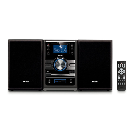
User Manual
DAB Micro System
©
Copyright 2008 Philips Consumer Electronics B.V. Eindhoven, The Netherlands
All rights reserved. No part of this publication may be reproduced, stored in a retrieval system or
transmitted, in any form or by any means, electronic, mechanical, photocopying, or otherwise without
the prior permission of Philips.
Published by SL 0820 Service Audio
Version 1.0
TABLE OF CONTENTS
PCBs Location & Version Variations ..................................... 1-2
Specifi cations ....................................................................... 1-3
Measurement Setup ............................................................. 1-4
Service Aids, Safety Instruction, etc ...........................1-5 to 1-7
Software Version Checking ..................................................... 2
Set Block Diagram ................................................................... 3
Set Wiring Diagram ................................................................. 4
Main Board & MCU Board ....................................................... 5
Key & LCD Board .................................................................... 6
Power Board ............................................................................ 7
Power AMP Board ................................................................... 8
ECO Power Board ................................................................... 9
Headphone & AUX & USB Board .......................................... 10
Set Mechanical Exploded View & Parts List .......................... 11
Printed in The Netherlands
Subject to modification
MCB395
Page
CLASS 1
LASER PRODUCT
© 3141 785 32850
/05
Advertisement
Table of Contents

Related Manuals for Philips MCB395/05


Summary of Contents for Philips MCB395/05
-
Page 1: Table Of Contents
LASER PRODUCT © Copyright 2008 Philips Consumer Electronics B.V. Eindhoven, The Netherlands All rights reserved. No part of this publication may be reproduced, stored in a retrieval system or transmitted, in any form or by any means, electronic, mechanical, photocopying, or otherwise without the prior permission of Philips. - Page 2 1 - 2 PCBS LOCATION POWER BOARD POWER AMP BOARD MAIN BOARD KEY & LCD BOARD MCU BOARD ECO POWER BOARD VERSION VARIATIONS Type /Versions: MCB395 Service policy Board in used: MAIN BOARD POWER BOARD POWER AMP BOARD KEY & LCD BOARD ECO POWER BOARD DAB MODULE USB &...
-
Page 3: Specifications
1 - 3 SPECIFICATIONS SPEAKERS AMPLIFIER 2-way Bass reflex system Output power ........2 x 50 W RMS ............100 W + 100 W MPO GENERAL INFORMATION Signal-to-noise ratio ......62 dBA (IEC) Frequency response ..40 – 15000 Hz, ± 3 dB AC Power ........ -
Page 4: Measurement Setup
1 - 4 MEASUREMENT SETUP Tuner FM Bandpass LF Voltmeter 250Hz-15kHz e.g. PM2534 e.g. 7122 707 48001 RF Generator e.g. PM5326 S/N and distortion meter e.g. Sound Technology ST1700B Use a bandpass filter to eliminate hum (50Hz, 100Hz) and disturbance from the pilottone (19kHz, 38kHz). Tuner AM (MW,LW) Bandpass LF Voltmeter... - Page 5 1 - 5 SERVICE AIDS WARNING All ICs and many other semi-conductors are susceptible to electrostatic discharges (ESD). Careless handling during repair can reduce life drastically. When repairing, make sure that you are connected with the same potential as the mass of the set via a wrist wrap with resistance.
- Page 6 1 - 6 INSTRUCTIONS ON CD PLAYABILITY Customer complaint "CD related problem" Set remains closed! check playability playability ok ? For flap loaders (= access to CD drive possible) "fast" lens cleaning cleaning method is recommended check playability playability ok ? Play a CD for at least 10 minutes check playability...
- Page 7 1 - 7 INSTRUCTIONS ON CD PLAYABILITY PLAYABILITY CHECK LIQUID LENS CLEANING Before touching the lens it is advised to clean the surface of the lens by blowing clean air over it. For sets which are compatible with CD-RW discs This to avoid that little particles make scratches on use CD-RW Printed Audio Disc ....7104 099 96611 the lens.
-
Page 8: Software Version Checking
2 - 1 2 - 1 SOFTWARE VERSION CHECKING Software checking: 1) MCU version : at standby mode, press and hold "ALBUM -" & "STOP" buttons at the same time. e.g. V2.01G... -
Page 9: Set Block Diagram
3 - 1 3 - 1 SET BLOCK DIAGRAM... -
Page 10: Set Wiring Diagram
4 - 1 4 - 1 SET WIRING DIAGRAM... - Page 11 5 - 1 5 - 1 CIRCUIT DIAGRAM - MAIN BOARD CD PART...
- Page 12 5 - 2 5 - 2 CIRCUIT DIAGRAM - MAIN BOARD DAB PART...
- Page 13 5 - 3 5 - 3 CIRCUIT DIAGRAM - MAIN BOARD TUNER PART...
- Page 14 5 - 4 5 - 4 CIRCUIT DIAGRAM - MAIN BOARD INTERFACE PART...
- Page 15 5 - 5 5 - 5 LAYOUT DIAGRAM - MAIN BOARD TOP VIEW...
- Page 16 5 - 6 5 - 6 LAYOUT DIAGRAM - MAIN BOARD BOTTOM VIEW...
- Page 17 5 - 7 5 - 7 PCB LAYOUT - MCU BOARD...
- Page 18 5 - 8 5 - 8 CIRCUIT DIAGRAM - MCU BOARD...
- Page 19 5 - 9 5 - 9 CIRCUIT DIAGRAM - MCU BOARD MEMORY PART...
-
Page 20: Key & Lcd Board
6 - 1 6 - 1 CIRCUIT DIAGARM - KEY & LCD BOARD KEY PART... - Page 21 6 - 2 6 - 2 CIRCUIT DIAGARM - KEY & LCD BOARD LCD PART...
- Page 22 6 - 3 6 - 3 LAYOUT DIAGARM - KEY & LCD BOARD TOP VIEW...
- Page 23 6 - 4 6 - 4 LAYOUT DIAGARM - KEY & LCD BOARD BOTTOM VIEW...
-
Page 24: Power Board
7 - 1 7 - 1 CIRCUIT DIAGARM - POWER BOARD PART 1... - Page 25 7 - 2 7 - 2 CIRCUIT DIAGARM - POWER BOARD SUB MCU PART...
- Page 26 7 - 3 7 - 3 LAYOUT DIAGARM - POWER BOARD TOP VIEW...
- Page 27 7 - 4 7 - 4 LAYOUT DIAGARM - POWER BOARD BOTTOM VIEW...
-
Page 28: Power Amp Board
8 - 1 8 - 1 CIRCUIT DIAGARM - POWER AMP BOARD... - Page 29 8 - 2 8 - 2 LAYOUT DIAGARM - POWER AMP BOARD...
-
Page 30: Eco Power Board
9 - 1 9 - 1 CIRCUIT DIAGRAM - ECO POWER BOARD... - Page 31 9 - 2 9 - 2 LAYOUT DIAGRAM - ECO POWER BOARD...
- Page 32 10 - 1 10 - 1 CIRCUIT DIAGRAM - HEADPHONE BOARD CIRCUIT DIAGRAM - AUX BOARD LAYOUT DIAGRAM - HEADPHONE BOARD LAYOUT DIAGRAM - AUX BOARD...
- Page 33 10 - 2 10 - 2 CIRCUIT DIAGRAM - USB BOARD LAYOUT DIAGRAM - USB BOARD...
- Page 34 11 - 1 11 - 1 SET MECHANICAL EXPLODED VIEW 12 11 10 CDMECH DAMP 54 55...
- Page 35 11 - 2 MECHANICAL & ACCESSORIES PARTS LIST 996510012826 DECORATION LENS BOTT PANEL REM 996510003938 REMOTE CONTROL 996510012799 996510016285 CD DOOR WOODEN SPEAKER BOX(L+R) 996510016270 DECORATION LENS MIDD PANEL W2 996510016286 FFC R/A TYPE 16PIN L=230MM 996510012851 996510016287 VOLUME KNOB FFC CABLE L=160MM 26PINS 996510016271 996510016288...
-
Page 36: Electrical Parts List
11 - 3 ELECTRICAL PARTS LIST C402 996510016290 994000003215 E.CAP 3300UF 16V 13X26MM M% IC502 RDS IC SAA6581T 996510012837 996510003731 C627 CBB CAP HMFS-5 0.68UF 63V IC503 IC V REGULATOR LD1117-3.3 996510012837 996510012838 C628 CBB CAP HMFS-5 0.68UF 63V IC600 I.C TDA8920BTH SOT566-3 996510012836 996510003730... - Page 37 11 - 4 ELECTRICAL PARTS LIST 996510003738 IC MAX809STR SOT-23 VD533 996510003727 DIODE 1SV262 VD534 996510003727 DIODE 1SV262 VR701 996510001059 ENCODER EC121102X2B-HA1-082 X300 996510003839 X'TAL 32.768KHZ 12.5PF X501 996510003724 X'TAL 75KHZ 20PF +/-20PPM X502 994000003209 X'TAL 4.332MHZ HC-49/S X801 994000005742 X'TAL 8.4672 MHZ 20PF 996510003735 X'TAL 24.000MHZ 20PF +/-20PPM...