Table of Contents
Advertisement
Owner's Manual
Distributed I/O
System-
Piccolo Interface
Unit (PIU) and
Piccolo-XR Unit
6802974C40-R
MOTOROLA and the Stylized M Logo are registered in the U.S.
Patent and Trademark Office. All other product or service names
are the property of their respective owners.
Copyright © 2009 Motorola
All Rights Reserved
6802974C40-R
@6802974C40@
Advertisement
Table of Contents

Related Manuals for Motorola Piccolo-XR

Summary of Contents for Motorola Piccolo-XR
- Page 1 System- Piccolo Interface Unit (PIU) and Piccolo-XR Unit 6802974C40-R MOTOROLA and the Stylized M Logo are registered in the U.S. Patent and Trademark Office. All other product or service names 6802974C40-R are the property of their respective owners. @6802974C40@ Copyright © 2009 Motorola...
- Page 2 In the event of a defect, malfunction or failure to conform to specifications established by seller, or if appropriate, to specifications accepted by Seller in writing, during the period shown, Motorola, at its option, will either repair or replace the product or refund the purchase price thereof, and such action on the part of Motorola shall be the full extent of Motorola’s liability hereunder.
- Page 3 Accordingly, any copyrighted Motorola computer programs contained in the Motorola products described in this instruction manual may not be copied or reproduced in any manner without the express written permission of Motorola.
- Page 4 This page left intentionally blank.
-
Page 5: Table Of Contents
PIU Electrical Connections............12 PIU Antenna Connection .............18 Piccolo–XR Installation ...............19 Piccolo–XR Screw Mounting Options ........20 Piccolo–XR Electrical Connections..........22 THE DIOS PIU AND PICCOLO-XR UNITS ......27 PIU Overview................27 PIU Communication Ports............28 PIU Connectors................29 PIU LED Operation ..............29 PIU Adapter Operation ...............30 Piccolo-XR Overview ..............35... -
Page 6: Contents
Contents APPENDIX A: PIU and PICCOLO-XR SPECIFICATIONS..37 PIU Specifications.................37 Environmental ................37 Mechanical ..................37 PIU Board..................38 Power....................39 PICCOLO XR Specifications ............42 Environmental ................42 Mechanical ..................42 PICCOLO XR Board..............42 Communication Ports ..............43 Power....................44 Regulatory Standards ..............46 Radio Network Freq Band Rated Power .......46 APPENDIX B: MODELS and ACCESSORIES...... -
Page 7: Introduction
The PIU functions as an interface between the host application (irrigation SW and HW) and the Piccolo–XR units. The PIU and Piccolo-XR are portable devices, which are used in fixed installations. The PIU uses one of its communication ports to link to the host application and radio communication to link to the Piccolo–XR units. - Page 8 Unit RS485 Piccolo RS232 Interface Unit Piccolo-XR Units I/O's Figure 1 DIOS –General System View The battery-operated Piccolo–XR unit is available in various models with different options of Inputs and Outputs. The Piccolo–XR unit can operate DC latch solenoids (outputs), read status and calculate flow of dry contact meters (inputs).
- Page 9 Introduction PIU - Piccolo Interface Unit The Piccolo Interface Unit (PIU; see Figure 2) is connected to the IRRInet Field Unit (FU) via RS232 or RS485 serial ports. Each PIU supports up to 256 Piccolo–XR units, with any available I/O combination, limited by the capacity of the IRRInet software only.
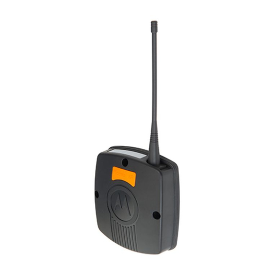
- Page 10 Introduction Figure 2 PIU – General View Piccolo–XR The Piccolo–XR is an intelligent, microprocessor based unit that can be used to monitor and control local units in a multi unit communication network. Piccolo–XR units communicate data to a PIU while functioning as intelligent nodes in Distributed I/O monitor and control systems.
-
Page 11: Safety Handling Instructions
For safety handling instructions, see the Product Safety and RF Energy Exposure Booklet for PIU and Piccolo XR Units, Motorola publication no. 6802974C70, which is distributed with the devices. The radio frequency band used by the DIOS system has not been harmonized throughout the entire European Economic Area (EEA). - Page 12 Introduction This page left intentionally blank.
-
Page 13: Installation
INSTALLATION General SAFETY SUMMARY The PIU and Piccolo–XR must be installed by qualified and authorized technicians, specifically qualified to handle high voltage if the installation C a u t i o n involves high-voltage connections/installations. If the PIU will be installed outdoors, an outdoor plastic housing complying with UL60950 standard clause 6 is required. -
Page 14: Piu Installation
Installation PIU Installation PIU Dimensions The unit dimensions are (see Figure 4): Width – 4.25" (108 mm), Height – 4.96" (126 mm), Height including antenna – 11.46" (291.1 mm), Depth – 1.67" (42 .6mm), Weight – 0.558 lb (253g) maximum. Figure 4 Dimensions of PIU Unit The PIU is enclosed in a plastic housing, allowing 3 mounting... -
Page 15: Mounting The Piu On A Wall Using Screws
Installation Before installing the PIU, verify that there is sufficient space around the unit according to the specific installation. Mounting the PIU On A Wall Using Screws 1. Secure two screws (not supplied) of maximum 0.37" (9.5 mm) head size to the wall, 3.256" (82.7 mm) apart. The wall-mounting template in Appendix D can be used to determine the space between both screws. -
Page 16: Mounting The Piu Using A Bracket
Installation Mounting the PIU Using a Bracket 1. Using four M3x6 or M3x8 screws, attach a bracket (not supplied) to the back of the PIU. The upper two bracket holes must be 3.19" (81 mm) apart, and the lower two bracket holes must be 2.40" (61 mm) apart and 2.13"... -
Page 17: Piu Din Rail Mounting
Installation PIU DIN Rail Mounting To mount the PIU on a DIN rail (not supplied), slide the PIU onto the rail at the grooves on the back of the unit. See Figure 7 and Figure 8. Figure 7 DIN Rail Attachment – Back View Figure 8 DIN Rail Attachment –... -
Page 18: Piu Electrical Connections
Installation PIU Electrical Connections Verify that all power connections are made in NOTE! accordance with the applicable local standards. PIU Ground Connections Use the FKN8254B cable to connect the grounding cable directly to the TB connector of the PIU as shown in Figure 9. The grounding connector is also used as an NOTE! ON/OFF switch, and the unit cannot be powered on... - Page 19 The PIU can be powered by various types of supply sources: Internal (9VDC) battery; External 6V or 12V DC battery; Motorola power supplies – controllers. For example: IRRInet XL, IRRInet XM, IRRIcom, MOSCAD; 24VAC. The unit DC voltage range is 6 to 16 volts. NOTE!
- Page 20 Installation Installation of an Internal Battery 1. Release the screw at the top of the battery chamber door, and slide the door out, as shown in Figure 10. 2. Connect the 9V battery cable (FKN8204B) to the DC power input connector on the back of the unit. 3.
- Page 21 Installation External Battery Power Connections The unit must be powered by a limited power source (12V DC) in accordance with standard UL/IEC 60950-1. See Power in Appendix A below. C a u t i o n This connection is used for normal operation of the PIU, when radio communication is required, or when RS485 or RS232 ports are used.
- Page 22 Installation External Power Supply Connections Use the applicable cable from the V152AH PIU installation kit to connect the PIU to Motorola standard controller power supply. 1. Release the screw at the top of the battery chamber door and slide the door out, as shown in Figure 10.
- Page 23 Installation 24VAC Power Connections The PIU must be connected to a power source equivalent to one or more of the following: a. A listed Direct plug-in unit. C a u t i o n b. A Class II power source (defined by the National Electrical Code (NEC) and the Canadian Electrical Code (CEC).
-
Page 24: Piu Antenna Connection
Installation PIU Antenna Connection Flexible Antenna: Attach the flexible monopole antenna to the antenna connector at the top of the unit. See Appendix C for detailed information. Pole Antenna: Attach the FKN8258B antenna cable to the antenna connector at the top of the unit. Connect the other end of the antenna cable to a customer-supplied pole antenna. -
Page 25: Piccolo-Xr Installation
Installation Piccolo–XR Installation Piccolo–XR Dimensions The unit dimensions are (see Figure 13): Width – 4.6" (117 mm) Height – 5.00" (127 mm) Hight including antenna – 11.46 (291.1 mm) " Depth –1.63" (41.5mm) Weight – 0.54 lb (240 gr) maximum. Figure 13 Dimensions of the Piccolo–XR Unit... -
Page 26: Piccolo-Xr Screw Mounting Options
Installation The Piccolo–XR unit can be attached to any vertical or horizontal surface using screws. Before mounting the Piccolo– XR, verify that sufficient clearance is left around the unit. Allow 8" (20 cm) clearance off the bottom of the Piccolo–XR case for the user cable and 6.3"... - Page 27 Installation 98mm 49mm Figure 14 Piccolo–XR Mounting Screw holes – Back View Figure 15 Piccolo–XR Mounting Options...
-
Page 28: Piccolo-Xr Electrical Connections
Installation Piccolo–XR Electrical Connections Verify that all power connections are made in NOTE! accordance with the applicable local standards. Wire (1)-Red Wire (2)-Black 1A Fuse User Cable-FKN8199B 6 V DC Battery Wire (17)-Yellow I/O's Ground Figure 16 Piccolo–XR Ground and DC Power Connections Piccolo–XR Ground Connections Connect the yellow wire (17) of the FKN8199B user cable to the PGND, as shown in Figure 16. - Page 29 Installation Power Connections The unit must be powered by a limited power source (6V DC) in accordance with standard UL/IEC 60950-1. See Power in Appendix A below. C a u t i o n The Piccolo–XR is powered by an external 6V DC battery source.
- Page 30 Installation User Cable-FKN8199B Solenoids Output Common Wire (9) Gray Sensors Input Common Wire (6) Green Figure 17 Piccolo–XR I/O Connections For proper operation, the Piccolo–XR unit must be NOTE! connected either to a flexible antenna or to a pole antenna. See Appendix C for antenna installation details.
- Page 31 Installation Table 1: Pin assignment of the Piccolo–XR user cable (FKN8199B) Connector PIN No COLOR DESCRIPTION Battery 6V (+) Black Battery 6V (–) Brown Solenoid 2 Orange Input 4 White Input 6 Green Input Common Blue Solenoid 3 Violet Solenoid 4 Gray Solenoid Common Pink...
- Page 32 Installation Table 2: Pin assignment of the Piccolo–XR user cable (FKN8199B) Connector DESCRIPTION PIN No COLOR Input 1 Light Green Input 2 Black/White Input 3 Brown/White Input 4 Orange Input 5 Red/White Input 6 White Input 7 Orange/White Input 8 Green/White Input Common Green...
-
Page 33: The Dios Piu And Piccolo-Xr Units
THE DIOS PIU AND PICCOLO-XR UNITS PIU Overview The PIU unit (see Figure 18) is comprised of the following: • Internal radio interfaces and a radio modem • A logic board • Communication ports LEDs 24V AC PGND/ RS485 Adaptor... -
Page 34: Piu Communication Ports
The DIOS PIU and Piccolo-XR Units DC Power In Figure 19 PIU Unit DC Power Connection– Rear View PIU Communication Ports The PIU has four ports: Only one of the two RS ports (232 and 485) can be NOTE! operated at a time, i.e. they do not operate together. -
Page 35: Piu Connectors
The DIOS PIU and Piccolo-XR Units PIU Connectors The PIU connectors (see Figure 18): • RS232 (RJ45, 8 pin) • RS485 (RJ10, 4 pin) • Adapter port (RJ10, 4 pin) • PGND And Power Switch (TB 3 pin) • 24 V AC PWR IN (2 pin) •... -
Page 36: Piu Adapter Operation
The DIOS PIU and Piccolo-XR Units PIU Adapter Operation The PIU can be used as an adapter to perform the following functions: • Communicating with the Piccolo–XR for configuration, monitoring or hardware test. • Downloading new software to a Piccolo–XR unit. - Page 37 The DIOS PIU and Piccolo-XR Units PIU Adapter Toolkit PC Piccolo-XR RS232 Communication RS232 Cable Connectors To PC RS485 Adapter To Piccolo XR Figure 20 PIU Adapter – Piccolo–XR Communication Mode Connections The grounding connector is also used as an ON/OFF...
- Page 38 The DIOS PIU and Piccolo-XR Units Downloading new software to a Piccolo–XR unit 1. Connect the PIU adapter RS232 port to the computer using the FTN6597B cable (see Figure 21). 2. Connect the PIU adapter unit to an external 12VDC battery or to an internal 9V battery.
- Page 39 The DIOS PIU and Piccolo-XR Units Communicating with a PIU unit 1. Connect the PIU unit RS232 port to the computer with the FTN6597B cable (see Figure 22). 2. Connect the PIU unit to an external 12VDC battery or to an internal 9V battery. (See page 12 for power options.)
- Page 40 The DIOS PIU and Piccolo-XR Units Downloading new software to a PIU 1. Connect the PIU adapter RS232 port to the computer with the FTN6597B cable (see Figure 23). 2. Connect the PIU adapter to an external 12VDC battery or to an internal 9V battery. (See page 12 for power options).
-
Page 41: Piccolo-Xr Overview
The DIOS PIU and Piccolo-XR Units Piccolo-XR Overview The Piccolo -XR Remote Terminal Unit (RTU) is comprised Logic board, which includes: • I/Os • Radio interface • Power supplies • Communication ports Radio 26 pin Connector Figure 24 Piccolo-XR Unit... -
Page 42: Piccolo-Xr Connector
The DIOS PIU and Piccolo-XR Units Piccolo-XR Connector The Piccolo -XR has one D-type 26 pin connector (see Figure 24). See Table 1 and Table 2 on pages 25–26 for more information Input/Output options A variety of I/O options is available for use with the Piccolo-XR, increasing the system flexibility. -
Page 43: Appendix A: Piu And Piccolo-Xr Specifications
APPENDIX A: PIU and PICCOLO-XR SPECIFICATIONS PIU Specifications Environmental -30 C to +60 C (-22 F to +140 F) Operating Temperature -40 C to +85 C (-40 F to + 185 F) Storage Temperature Relative Operating Humidity 0 to 95% without condensation @ +50 C (122 F) -
Page 44: Piu Board
APPENDIX A: PIU AND PICCOLO-XR SPECIFICATIONS PIU Board Communication Ports RS232 Serial RS-232 RS485 Multi Drop 2 Wire Adapter Serial interface between PIU as adapter and PICCOLO–XR (UART levels) Boot-Strap Software programming port Internal Radio RF Frequency UHF 450–470 MHz (actually 450.0125-469.9875) OR... -
Page 45: Power
APPENDIX A: PIU AND PICCOLO-XR SPECIFICATIONS 2KHz 15% TX deviation: RX BER BER<1% (See Note 5 on p. 41.) Red, Orange, Green LEDs (SW Programmable) Power Input Voltage External Source 6.00 to 16.00 VDC e.g. lead acid (DC Power In) battery or solar panel, typically used in irrigation systems. - Page 46 APPENDIX A: PIU AND PICCOLO-XR SPECIFICATIONS PIU Mode (Using a 12 V or 6 V external power source) Radio Transmission (TX power-10 mW) 25 – 40 mA (PWR IN =14 V) 65 – 90 mA (PWR IN = 6 V) (TX power-100 mW) 30 –...
-
Page 47: Environmental
APPENDIX A: PIU AND PICCOLO-XR SPECIFICATIONS Note 1: Power In = 9 V DC (Adapter), RS232 = shutdown, RS485 = disable, Radio (On Board Circuits) = off, internal Radio is off. RS232 cable connected. Note 2: Power Supply = 14 V DC (PIU), RS232 = shutdown, RS485 = disable, Radio (On Board Circuits) = off, internal Radio is off. -
Page 48: Piccolo Xr Specifications
APPENDIX A: PIU AND PICCOLO-XR SPECIFICATIONS Mechanical 127x117x41.5 mm 1 mm Dimensions (5.00"x4.60"x1.63") 240 gr 24 gr (0.54 lb 0.05 lb) Weight User Connection 17 pin User Cable (26 pin D-type connector) Wire Gauge 22 AWG PICCOLO XR Board... - Page 49 APPENDIX A: PIU AND PICCOLO-XR SPECIFICATIONS Internal Radio RF Frequency UHF 450–470 MHz or * ** UHF 430-450 MHz (Service Toolkit programmable) Duty Cycle ratio < 10% (relative to a 1 hour period for ISM band only) Channel spacing 12.5 KHz...
-
Page 50: Power
APPENDIX A: PIU AND PICCOLO-XR SPECIFICATIONS Radio Transmission Radio Off 1.2 – 1.5 mA (See Notes 6, 7 p. 44.) (TX power-10mW) 65 – 90 mA (See Notes 8, 9 p. 44.) (TX power-100mW) 100 – 150 mA (See Notes 8, 9 p. 44.) 30 –... - Page 51 APPENDIX A: PIU AND PICCOLO-XR SPECIFICATIONS Note 11: For radio functionality external Power In minimum voltage=5 V. Unlicensed Frequency Restrictions (For UHF 430-450 MHz radio only) When using a frequency in the unlicensed ISM range (433.0625-434.7875 MHz, not including 443.95 MHz and 444.8625 MHz), certain...
-
Page 52: Regulatory Standards
APPENDIX A: PIU AND PICCOLO-XR SPECIFICATIONS Regulatory Standards US and Canada Grant of Equipment Authorization IMPORTANT: Unauthorized repairs or modifications could result in permanent damage to the equipment and void your warranty and your authority to operate this device under Part 15 of the FCC Rules. - Page 53 APPENDIX A: PIU AND PICCOLO-XR SPECIFICATIONS Piccolo XR Units, Motorola publication no. 6802974C70, which is distributed with the devices. European Union Notification The CE mark is the official marking required by the European Community for all Electric and Electronic equipment that will be sold, or put into service for the first time, anywhere in the European community.
- Page 54 APPENDIX A: PIU AND PICCOLO-XR SPECIFICATIONS Conformity for RoHS Compliance This Motorola product is in compliance with the essential requirements and other relevant provisions of Directive 2002/95/EC, Restriction of the use of certain Hazardous Substances (RoHS) in electrical and electronic equipment.
-
Page 55: Appendix B: Models And Accessories
APPENDIX B: MODELS and ACCESSORIES General The following tables describe the available models, options and accessories. DIOS Models Model Piccolo Interface Unit (PIU) F4604B Piccolo–XR DC F4614B PIU Options Option ADD: RS-485 Option (indoor) V440AD ADD: RS-232 Cable 3 m V666AA ADD: Antenna for PIU, 450-470 MHz V208AJ... - Page 56 Appendix B: Models and Accessories Piccolo-XR Options Option ADD: 1 DI / 1DO Option V608AE ADD: 2 DI / 2DO Option V379AK ADD: 4 DI / 4DO Option V118AJ ADD: 7 DI / 1 DO Option V115AN ADD: 8 DI / 0 DO V508AF ADD: Antenna for Piccolo–XR,...
-
Page 57: Appendix C: Antenna
APPENDIX C: ANTENNA General The PIU and Piccolo–XR units can be connected either to a flexible or to a pole antenna. The antenna connector (see Figure 25), located at the top of the unit, is used for both antenna types. Piccolo - XR Antenna SMA Connector SMA Connector... -
Page 58: Pole Antenna
Appendix C: Antenna Pole Antenna The pole antenna installation must comply with the following requirements in order to ensure optimal performance and guarantee that human exposure to radio frequency electromagnetic energy is within the guidelines set forth by the applicable local regulations. The antenna must be mounted outdoors, preferably on a tower, if possible. -
Page 59: Pole Antenna Installation
Appendix C: Antenna Pole Antenna installation SMA to SMA option Antenna Antenna Support Rubber Washer Lock Adjustable Washer Straps SMA Connector SMA to SMA Antenna Cable Rubber Sleeve SMA Connector Figure 27 SMA to SMA type PIU/Piccolo–XR Pole Antenna 1. Connect a flexible antenna to the antenna support plate using rubber washers, lock washer and a nut (see Figure 27). - Page 60 Appendix C: Antenna SMA TO N-TYPE Antenna Antenna Support Rubber Washer Lock Washer SMA Connector Adjustable N-Type Straps Connector SMA to N-Type Antenna Cable N-Type Washer Figure 28 SMA to N-Type Pole Antenna 1. Connect a flexible antenna to the antenna support plate using rubber washers, lock washer and a nut (see Figure 28).
- Page 61 Appendix C: Antenna Pole Antenna Dimension Figure 29 shows recommended dimensions for a supporting plate for the pole antenna. 200mm 270mm Figure 29 PIU/Piccolo–XR Pole Antenna Supporting Plate Dimensions...
- Page 62 Appendix C: Antenna This page left intentionally blank.
-
Page 63: Appendix D: Piu/Piccolo-Xr Mounting Templates
APPENDIX D: PIU/PICCOLO–XR MOUNTING TEMPLATES Use the following template for PIU wall mounting. 3.26" 82.7mm Figure 30 PIU Wall Mounting Template (Full Size) Figure 31 PIU Back... - Page 64 Appendix D: PIU/Piccolo – XR Mounting Templates The following is a template that can be used for mounting the Piccolo–XR unit. 2.126" 54mm Figure 32 Piccolo–XR Mounting Template (Full Size)
- Page 68 MOTOROLA and the Stylized M Logo are registered in the U.S. Patent and Trademark Office. All other product or service names are the property of their respective owners. Copyright © 2009 Motorola All Rights Reserved 6802974C40-R @6802974C40@ August 2009...