Table of Contents
Advertisement
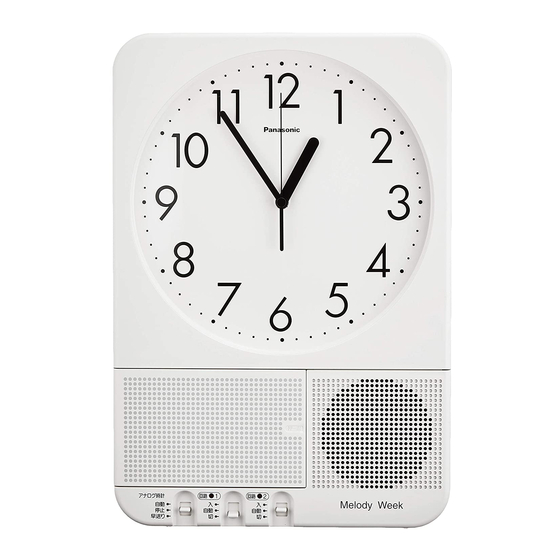
Pa n aso n ic
Office Clock (Electronic Bell Timer with Recording Function)
'
Thank you for purchasing MATSUSHITA Melody Week, Model TD736/738/739.
Precautions for a person
in charge of installation
Precautions
for user
Melody Week
Instruct i on/Installat i on Manual �-----
Model: TD736 (110 V AC)
TD738 (220 V AC)
TD739 (240 V AC)
• Be sure to read the Installation Part of this manual before installing
the Melody Week properly.
• A person in charge of installation shall be qualified as electric
engineering technician.
• Hand over this Instruction/ Installation Manual to a user without fail.
• Be sure to read the Instruction Part of this manual before using the
Melody Week properly.
• Keep this Instruction / Installation Manual without fail.
/
- -
Infringement of Copyright:
Musical compositions that you
recorded may fringe a copyright.
You cannot use them without the
permission of the right holder.
• Precautions for safety
• Contents
• Operation Part
• Installation Part
For store
Pl
•
•
•
•
0
•
. . . .
. .
P2
,
P4
•
•
0
•
•
•
. . . . . .
P28
Advertisement
Table of Contents

Related Manuals for Panasonic Melody Week

Summary of Contents for Panasonic Melody Week
- Page 1 Model: TD736 (110 V AC) TD738 (220 V AC) TD739 (240 V AC) Thank you for purchasing MATSUSHITA Melody Week, Model TD736/738/739. Precautions for a person • Be sure to read the Installation Part of this manual before installing in charge of installation the Melody Week properly.
- Page 2 Melody Week becomes out of order. eoo not disasse m ble or m odi f y the Melody Week. ------Failure to observe this warning may cause an electric shock or fire. ------...
-
Page 3: Table Of Contents
+++++ +++++ Contents Warnings f or sa f ety · · · · · · · · · · · · · · · · · · · · · · · · · · · · · · · · · · · · · · · · · · · · · · · · · · · · · · · · · · · · · · · · · · · · C ontents ·... - Page 4 ••••• + +++ + Contents I installat ion Part Prec auti ons befo re inst allat ion · · · · · · · · · · · · · · · · · · · · · · · · · · · · · · · · · · · · · · · · · · · · · · · · · · · · · · ·· Installatio n method ·...
-
Page 5: The Melod Y Week Has The F Oll Owing F Eatures
(Refer to page 31 ). 6. Capable of announcing visitors When an external switch (sensor, etc.) signal is entered, the Melody Week can be used for announcement of visitors (Refer to page 24). 7. Capable of making announcements using a microphone Announcements can be made by connecting a microphone (Refer to page 5). - Page 6 Name of each part and its function Minute hand Hour hand • Main unit Analo g clock • Pull the right hand 1 1 2 side of the main unit to open the cover. Panasoni 3· Second hand Speaker Microphone input jack Channel 2 �...
- Page 7 Terminal block Melody signal jack Power lamp (green) (see pages 31, 32) (see pages 32) Time setting knob (see page 10) • Adjust the hands on the Incoming linehole Rating plate analog clock. Main unit battery (see page 25) Main unit battery connector (removed during transportation)
-
Page 8: Lcd Display
Program unit release button � display ____ ��--- :: _ . , . , . , Panasonic Program No. Sun. Mon. Tue. We . Thu. Fri. Sat. ! S u mmerTimel Output Time [- _,, J I II I '1�1, �1� 1,, _, - Year•... -
Page 9: P Reparation
The analog clock signal connector is pulled out during transportation. Set the Power failure back-up going. The Melody Week will continue clock operation even at power failure and/or when a program unit is removed from the main unit. This function has been turned OFF at a factory. - Page 12 Program Setting • How to set the weekly program (an example of making a new setting or adding a setting) Example: Using channel 1, play melody No.1 and output a control signal to switch ON the lights for 22 seconds at 8:30 on Monday thru Friday every week. Program No.
-
Page 13: How To Check, Change, Or Clear The Weekly Progra M
• How to check, change, or clear the weekly program Example: To check, change or clear the contents of the program number 15 set for the channel 1. Mode select Program No. Mon. Tue. Wed. Thu. Fri. OutputTlme 30 [ 22 ] !!�t�... -
Page 14: P Rogra M Setting
Program Setting • How to set the holiday program (procedure for setting a new program or adding a program) Example: Interrupt the scheduled program for May 5 on channel 1. Mode select Set the switch to the[!i[I - -M o - �... -
Page 15: How To Check, Change, Or Clear The Ho L Iday Program
• How to check, change, or clear the holiday program Example: To change the holiday schedule from December 25 to January 7 or clear it at the channel-1. Set the Mode select � 1 � switch to themm] [� -- ·-· M onth IHoliday!Calllposition. - Page 18 Recording, Playing and Editing the Melodies Press the .,./II button to ·· • 5 : start recording. �;uWed. Lf f Start o . Pause The recording time is MelodyC, counted. To stop recording for a ..'nl,,. J..t �;uWed..I ,,. brief period of time, :- u ..
-
Page 19: How To Play The Melody
• How to play the melody Mode select Play/Rec./Edit position. ' I / ..._ Play _..., Rec. _..., Edit , The LCD display returns to / I ' the Play/Rec./Edit initial screen. Press the[illn!Jbutton. n :, :, The LCD display shows the Sun. -
Page 20: How To Adjust The Sound Level
Recording, Playing and Editing the Melodies • How to adjust the sound level (effective only when the program unit is attached to the main unit) The sound level of the melody can be adjusted so that each melody is played at similar sound level (Default melodies are set at the same sound level). - Page 21 • How to edit (clear, fore-cut, back-cut) the recorded melodies When recorded melodies or announcements (No.5 to 8) are cleared or recorded, unnecessary fore or back parts, which have been recorded with backward and forward allowance made, can only be cleared. theli•if=tiMi •...
-
Page 26: Interrupt Input
Priori t y of Melody Ou t pu t There are five kinds of methods to produce melody outputs. Priority of melody output for different operations shall be as follows: (1) Channel 1 output select switch (2) Channel 2 output select switch, (3) Channel 1 program (4) Channel 2 program (5) Interrupt input (annunciation of visitor) R e n/ ac in g t h e b at t e r y... - Page 27 P r ogram examples Wiring diagrams below only indicate connections to other equipment. They do not show the actual channel. [Example 1]: Playing melodies through an internal speaker and an external speaker Speaker • !J)j Example: Play "The Bell of Westminster Abbey" at 9:00 AM on Monday to Friday. Program Do not set.
- Page 30 Setting up the main unit • Temporarily attaching the mounting screws Put this sheet on the wall where the Melody Week will be installed using i+�,, , ¥1 adhesive tape or pins. Drill holes for plugs in a position on the pattern sheet.
- Page 31 Output specifications • Melody output External speaker output (80) Output capable of expanding only one external speaker • Max. output: 3W (load impedance of 80) • Compatible speaker: 80, 3W or more (Since maximum rated output of a built-in amplifier is 3W, use a speaker with rated output of 3W or more.) -�MtW 1.
- Page 32 --- ------' "'-'""l--n Note: Remove jumper lines which are indicated by a dotted line and connected between the terminals of the electro-magnetic switch. If the jumper lines are connected as it is, the Melody Week is not operated properly. -31-...
- Page 33 ' f§ When the melody signal is amplified by an amplifier Amplifier Start-up Speaker signal input output Speaker Power supply -�MtW The melody signal wire should be used exclusively. If the melody signal wire is put in the same pipe arrangement as a telephone line, speaker wires or power wiring, noise may be produced.
- Page 34 Wiring method No special provisions 600V vinyl insulated wire Supply voltage: • Single wire: Dia.1.2 to 1.6 mm 110 V AC, 220 V AC or • Twisted wire: 1.25 to 2 mm 240 V AC± 10 % Same as above Depends on loads 100 m Dia.
- Page 35 " 3 Connection to the terminals Make connections in the following manners as shown below. -�MtW • Appropriate tightening torque: 0.8 to 1.2 N · m (8.2 to 12.2 Kgf · cm) 1. Turn off the power before make connections. 2.
- Page 36 Wiring example Unit:mm. • Main unit 3 - 21(Incomin ( Incoming ) 2- 28.2 line hole 2 · · . . _ . · l 3� ('I) · . 8 · 5 . . · · · . . 7 Steady rest hole •...
-
Page 37: Useful Life
Specifications Models TD736 TD738 TD739 Power supply voltage 110VAC 220VAC 240VAC Frequency Common use for 50/60 Hz Driving method Electronic type (except for analog clock: step motor driving method) Rated power consumption Approx. 1 O W (Max. 20 W for melody output) Accuracy of time Crystal oscillation type: ±5 seconds /month (at 25°C) Power supply at power failure... - Page 40 Program unit for TD736, TD738 or TD739 TD73601507 Nickel-metal-hydride battery TD73602457 Instruction / Installation manual TD73608107 For maintenance parts, contact your dealer or a person in charge of installation. Panasonic Corporation 1048,Kadoma,Osaka, 571-8686, Japan Phone : (06) 6908-1131 Instruction manual No.: TD73608107 Ta1010-1121 -39-...