Table of Contents
Advertisement
Quick Links
Advertisement
Table of Contents

Related Manuals for Make Noise phonogene


Summary of Contents for Make Noise phonogene
- Page 1 PHONOGENE v2.7...
-
Page 2: Table Of Contents
Overview -----------------------------------------------------------------------6 Panel Controls ---------------------------------------------------------------7 Getting Started ------------------------------------------------------10 Recording Process ------------------------------------------------------11 Splice --------------------------------------------------------------------12 Microsound -----------------------------------------------------------------13 Chronological Inspection of Sound DNA ----------------------14 PHONOGENE Firmware v.372 Update -----------------------------------------15 Hidden Functions and Routines ---------------------------------16 Patch Examples ---------------------------------------------------------17 Advanced Patch Techniques --------------------------------------22 Venturing Further ----------------------------------------------------------26... -
Page 3: Fcc
This equipment generates, uses, and can radiate radio frequency energy and, if not installed and used in accordance with the instruction manual, may cause harmful interference to radio communications. makenoisemusic.com Make Noise Co., 414 Haywood Road, Asheville, NC 28806... -
Page 4: Limited Warranty
Make Noise to be the fault of the user are not covered by this warranty, and normal service rates will apply. During the warranty period, any defective products will be repaired or replaced, at the option of Make Noise, on a return-to-Make Noise basis with the customer paying the transit cost to Make Noise. -
Page 5: Installation
Eurorack style bus board, minding the polarity so that the RED stripe on the cable is oriented to the NEGATIVE 12 Volt line on both the module and the bus board. On the Make Noise 6U or 3U Busboard, the negative 12 Volt line is indicated by the white stripe. -
Page 6: Overview
It is possible to render the source material completely unintelligible, to cut busted loops, to distort digitally, to obscure, to regenerate to the point of almost no signal integrity. This is the nature of the PHONOGENE. If you seek the perfect looping tool, in the most contemporary sense of the word “loop, ”... -
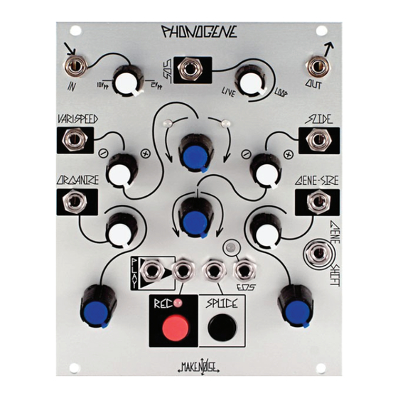
Page 7: Panel Controls
5. Signal Output: 10Vpp (depending upon Signal Input attenuator setting and source material), AC coupled. 6 & 7. Vari-Speed and Splice Indicator LEDs: These LEDs tell user in which direction the PHONOGENE is playing. The LEFT Blue (7) LED indicates reverse playback, right Orange LED (6) indicates forward playback. When no LEDs are lighted, playback is... - Page 8 Splice Indicator LEDs (6 & 7 ) ashes whenever this control ends a new Splice. 14. Play Pulse Input: at each rising edge signal applied to Play Pulse Input, PHONOGENE triggers playback. At end of loop or Splice, PHONOGENE looks at Play Pulse Input. If High, it plays again. If Low, PHONOGENE does not play. This Input is normalized to be High.
- Page 9 Nondestructive. At 0V there is no e ect. Range 0V to +8V. 26. Gene-Size Input Attenuator: unipolar attenuator for Gene Size. 27. Gene Shift: clock signal at this input advances PHONOGENE to next Gene, in chronological order. Always dependent upon the Gene Sizesetting. Needs at least 1.5V trigger signal to operate.
-
Page 10: Getting Started
Erase Routine It is best to start with a cleared memory. To Reset the PHONOGENE and start fresh you need to enter the Erase Routine, where you may erase Splice markers and the Audio Bu er (aka Loop, aka Recording, aka Sample). To erase all Splices, press and hold Splice button (18) until the Rec LED (17) starts ashing. -
Page 11: Recording Process
Sound On Sound Control (3, 4) sets the balance of the Live Signal and previously recorded Loop Signal. While the PHONOGENE does not record in reverse, it plays back in reverse while recording for Sound On Sound, so it is possible to have two sounds playing in opposite directions. -
Page 12: Splice
When Vari-Speed is set to greater or less then 12:00, playback starts from where it was halted. The Play Pulse IN also stops and starts playback, but in a very di erent way. At the end of each loop or splice, the PHONOGENE looks at the PLAY Pulse Input (14), if it is high, then PHONOGENE continues to play, if it is low, PHONOGENE stops at end of loop or splice. -
Page 13: Microsound
If the individual Samples that comprise a digitally recorded sound recording make up the DNA of the sound, then we would refer to these small clusters of samples as Genes. The PHONOGENE is a Single Gene device, meaning that one cluster of samples is heard at a time. -
Page 14: Chronological Inspection Of Sound Dna
Using the Gene-Shift Clock/ Pulse Input (27) it is possible to play through the Genes in Chronological order. This is Synchronous Granulation. At the rising edge of each Clock or Pulse, the PHONOGENE jumps to the next Gene and plays that Gene at the rate and direction determined by Vari-Speed, until the next Clock or Pulse arrives at the Gene-Size Input. -
Page 15: Phonogene Firmware V.372 Update
This is a great mode for building walls of sound, drones or making crude echo FX. » PHONOGENE still minds Splices and Vari-Speed, Gene Size, Shift, and Slide functions. Any modulation of these parameters are recorded. Be sure to set the Mix control according to your desired results. For example, live input processing requires the Mix to be set at around 50%, while massaging content that has been captured needs Mix set to 100% Wet. -
Page 16: Hidden Functions And Routines
REC button (16) once. PLAY Pulse Input (14): this input is normalized HIGH, so that with nothing patched, the PHONOGENE always plays according to Vari-Speed setting. Patching something to this input stops the PHONOGENE, if the applied signal is below 1.5V SOS CV IN (3): this control input is normalled to +10V and is connected directly to the SOS Attenuator (4), therefore with nothing patched the SOS CV IN, SOS Attenuator acts as a panel control for the parameter, by setting an o set. -
Page 17: Patch Examples
Patch a dummy cable, or a manual gate, such as Pressure Points Gate Output, to PHONOGENE Play Pulse Input (14). Let PHONOGENE play to end of recording. Once playback has reached the end and stopped, patch the MATHS Channel 1 End Of Rise OUT to PHONOGENE Splice Pulse Input (19). - Page 18 “loggish.” Set MATHS CH. 1 attenuverter full counter clockwise so that the resulting signal is inverted. Set MATHS CH. 4 full clockwise. Null MATHS CH. 2 and 3. Patch MATHS Sum Output to PHONOGENE Vari-Speed CV Input and set the associated attenuverter to about 2:00 Now, use the pressure applied to the PRESSURE PLATES to control the Playback Speed and Direction.
- Page 19 With nothing patched to Signal IN (2), and Vari-Speed (9) at around 70%, press Record and let it run to end. Set-up a clocked patch with a Sequenced Sound Source (VCO->LPG) patched to PHONOGENE Signal IN. Strike LPG with division of Master Clock.
- Page 20 EOS (multed) -> DPO Strike Wogglebug Stepped Random -> DPO 1v/Oct DPO Final -> PHONOGENE IN Engage Broken Echo mode. Adjust Wogglebug Chaos Balance control to taste to choose melodic range. Adjust SOS to ~1:00. Adjust or VC Gene Size, Varispeed, Slide and direction to “play” the patch. Granular exploration is recorded into the bu er,...
- Page 21 (Alternatively, use PHONOGENE’s End of Splice trigger to clock the ECHOPHON, multiply the ECHOPHON Tempo, and clock RENE with ECHOPHON Clock Out). Patch sequenced audio to PHONOGENE IN. Adjust SOS to between 9:00 and 3:00 according to tast. Each loop of the melody is slightly out of time with the previous as they stack on each other, creating rhythmic and phasing e ects.
-
Page 22: Advanced Patch Techniques
Make Noise system. These concepts are slightly more advanced in that they rst require you to record-- or edit, a sample into a looping “break,”... - Page 23 Gene’s as they are played back linearly. You may now compress the sample by slightly adjusting the Vari-Speed Panel Control counter-clockwise. This sounds best when the Wogglebug’s Clock is Multed to the PHONOGENE’s Play Input. Setting up the Sequencer:...
- Page 24 If you haven’t moved the Vari-Speed Panel Control from where it was set when you originally recorded, you may easily re-record a new loop by unpatching from the PHONOGENE’s Play and SLIDE CV Inputs, rotating the Sound On Sound Panel Control back to LIVE.
- Page 25 Now, with Organize counter-clockwise and its associated Attenuator full clockwise, patch PRESSURE POINTS Tuned Voltages Output Y to the Organize CV Input, and the CH.4 Common Gate Output to the PHONOGENE’s Play Input. Each Touch Plate may now be set to select and Trigger a new Splice, using the associated Row Y Tuned Voltage Panel Controls. Chain up to four PRESSURE POINTS to select up to (16) di erent Splices within the original sample.
-
Page 26: Venturing Further
Venturing Further:...