Table of Contents
Advertisement
Quick Links
S
ervice
M anua l
HIDE-AWAY DAB TUNER
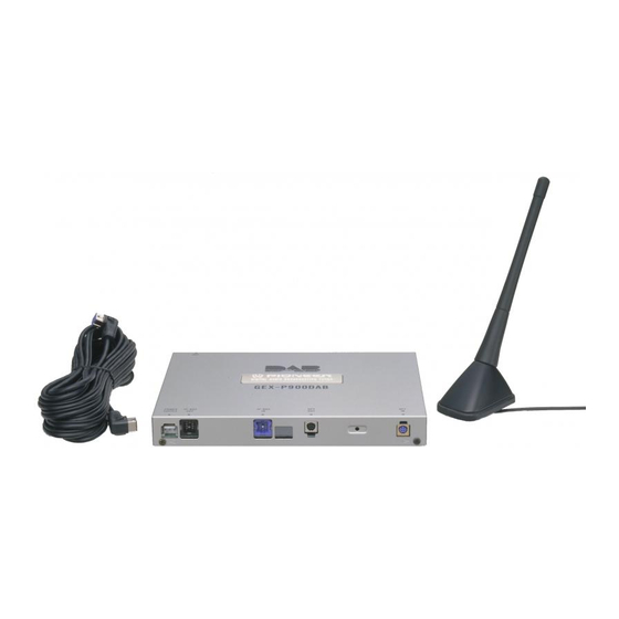
GEX-P900DAB
CONTENTS
1. SAFETY INFORMATION ............................................2
2. EXPLODED VIEWS AND PARTS LIST .......................2
3. SCHEMATIC DIAGRAM .............................................6
4. PCB CONNECTION DIAGRAM ................................24
5. ELECTRICAL PARTS LIST ........................................28
6. ADJUSTMENT..........................................................35
PIONEER ELECTRONIC CORPORATION
PIONEER ELECTRONICS SERVICE INC.
PIONEER ELECTRONIC [EUROPE] N.V.
PIONEER ELECTRONICS ASIACENTRE PTE.LTD. 501 Orchard Road, #10-00, Wheelock Place, Singapore 238880
C PIONEER ELECTRONIC CORPORATION 1998
4-1, Meguro 1-Chome, Meguro-ku, Tokyo 153-8654, Japan
P.O.Box 1760, Long Beach, CA 90801-1760 U.S.A.
Haven 1087 Keetberglaan 1, 9120 Melsele, Belgium
7. GENERAL INFORMATION .......................................37
7.1 IC ........................................................................37
7.2 TEST MODE........................................................52
7.3 EXPLANATION ...................................................54
7.3.1 CIRCUIT DESCRIPTION ............................54
7.3.2 BLOCK DIAGRAM .....................................59
8. OPERATIONS AND SPECIFICATIONS.....................60
K-FES. JULY 1998 Printed in Japan
ORDER NO.
CRT2193
EW
Advertisement
Table of Contents

Related Manuals for Pioneer GEX-P900DAB

Summary of Contents for Pioneer GEX-P900DAB
-
Page 1: Table Of Contents
P.O.Box 1760, Long Beach, CA 90801-1760 U.S.A. PIONEER ELECTRONIC [EUROPE] N.V. Haven 1087 Keetberglaan 1, 9120 Melsele, Belgium PIONEER ELECTRONICS ASIACENTRE PTE.LTD. 501 Orchard Road, #10-00, Wheelock Place, Singapore 238880 C PIONEER ELECTRONIC CORPORATION 1998 K-FES. JULY 1998 Printed in Japan... -
Page 2: Safety Information
GEX-P900DAB 1. SAFETY INFORMATION This service manual is intended for qualified service technicians; it is not meant for the casual do-it-yourselfer. Qualified technicians have the necessary test equipment and tools, and have been trained to properly and safely repair complex products such as those covered by this manual. - Page 3 GEX-P900DAB - PACKING SECTION PARTS LIST NOTE: - Parts marked by “*”are generally unavailable because they are not in our Master Spare Parts List. ∇ mark on the product are used for disassembly. - Screws adjacent to Mark No. Description Part No.
- Page 4 GEX-P900DAB 2.2 EXTERIOR...
- Page 5 GEX-P900DAB - EXTERIOR SECTION PARTS LIST Mark No. Description Part No. Mark No. Description Part No. 1 Screw BSZ26P060FMC 26 Connector(CN262) CKS3409 2 Screw BSZ30P060FMC 27 Connector(CN261) CKS3414 3 Screw BSZ30P060FZK 28 Shield CNC7512 4 Plate CAH1654 29 Holder CNC7518...
-
Page 6: Schematic Diagram
GEX-P900DAB 3. SCHEMATIC DIAGRAM 3.1 MAIN UNIT(1/3) Note: When ordering service parts, be sure to refer to “EXPLODED VIEWS AND PARTS LIST” or “ELECTRICAL PARTS LIST”. Large size SCH diagram Guide page Detailed page SYSTEM CONTROL... - Page 7 GEX-P900DAB SELECTOR ISOLATOR MUTE POWER SUPPLY, ASENSE,BSENSE CEK1033 1.4mH POWER SUPPLY...
- Page 8 GEX-P900DAB...
- Page 9 GEX-P900DAB...
- Page 10 GEX-P900DAB...
- Page 11 GEX-P900DAB...
- Page 12 GEX-P900DAB 3.2 MAIN UNIT(2/3) Large size SCH diagram BAND3,RF AMP Guide page L-BAND,RF AMP Detailed page ANT,DUMP POWER SUPPLY L-BAND DOWN CONVERTOR...
- Page 13 GEX-P900DAB 1st MIXER 2nd MIXER SAW FILTER NULL DETECTOR DIGITAL SECTION...
- Page 14 GEX-P900DAB...
- Page 15 GEX-P900DAB...
- Page 16 GEX-P900DAB...
- Page 17 GEX-P900DAB...
- Page 18 GEX-P900DAB 3.3 MAIN UNIT(3/3) Large size SCH diagram Guide page Detailed page DAB DECODER 3.3V to 5V LEVEL TRANSITION 5V to 3.3V LEVEL TRANSITION VCXO CLOCK CONTROL CLOCK CONTROL...
- Page 19 GEX-P900DAB 48/44.1kHz CONVERSION DIGITAL INTERFACE TRANSMITER SELECTOR SELECTOR OPT IN/OUT...
- Page 20 GEX-P900DAB...
- Page 21 GEX-P900DAB...
- Page 22 GEX-P900DAB...
- Page 23 GEX-P900DAB...
-
Page 24: Pcb Connection Diagram
GEX-P900DAB 4. PCB CONNECTION DIAGRAM 4.1 MAIN UNIT MAIN UNIT... - Page 25 GEX-P900DAB NOTE FOR PCB DIAGRAMS 1. The parts mounted on this PCB include all 2. Viewpoint of PCB diagrams necessary parts for several destination. Capacitor Connector For further information for respective SIDE A destinations, be sure to check with the schematic diagram.
- Page 26 GEX-P900DAB MAIN UNIT...
- Page 27 GEX-P900DAB SIDE B...
-
Page 28: Electrical Parts List
GEX-P900DAB 5. ELECTRICAL PARTS LIST NOTE: - Parts whose parts numbers are omitted are subject to being not supplied. - The part numbers shown below indicate chip components. Chip Resistor RS1/_S___J,RS1/__S___J Chip Capacitor (except for CQS..) CKS.., CCS.., CSZS..=====Circuit Symbol and No.===Part Name Part No. - Page 29 GEX-P900DAB =====Circuit Symbol and No.===Part Name Part No. =====Circuit Symbol and No.===Part Name Part No. ------ ------------------------------------------ ------------------------- ------ ------------------------------------------ ------------------------- Diode KV1841E Resonator 18.432MHz CSS1440 Diode KV1841E Semi-fixed 10kΩ(B) CCP1181 Diode KV1841E Filter CTF1452 Diode KV1841E Filter CTF1456 Diode...
- Page 30 GEX-P900DAB =====Circuit Symbol and No.===Part Name Part No. =====Circuit Symbol and No.===Part Name Part No. ------ ------------------------------------------ ------------------------- ------ ------------------------------------------ ------------------------- RS1/10S102J RS1/16S222J RS1/10S102J RS1/16S101J RS1/10S102J RS1/16S0R0J RS1/10S102J RS1/16S223J RS1/16S102J RS1/16S222J RS1/16S105J RS1/16S222J RS1/16S471J RS1/16S183J RS1/16S102J RS1/16S682J RS1/16S102J RS1/16S102J RS1/16S222J...
- Page 31 GEX-P900DAB =====Circuit Symbol and No.===Part Name Part No. =====Circuit Symbol and No.===Part Name Part No. ------ ------------------------------------------ ------------------------- ------ ------------------------------------------ ------------------------- RS1/16S473J RS1/16S102J RS1/16S473J RS1/16S272J RS1/16S101J RS1/16S681J RS1/16S153J RS1/16S152J RS1/16S332J RS1/16S151J RS1/16S184J RS1/16S682J RS1/16S274J RS1/16S471J RS1/16S220J RS1/16S103J RS1/16S473J RS1/16S473J RS1/16S271J...
- Page 32 GEX-P900DAB =====Circuit Symbol and No.===Part Name Part No. =====Circuit Symbol and No.===Part Name Part No. ------ ------------------------------------------ ------------------------- ------ ------------------------------------------ ------------------------- RS1/16S104J CCSQCH150J50 RS1/16S104J CCSRCH150J50 RS1/8S2R0J CCSRCH150J50 RS1/8S2R0J CKSRYB104K16 RS1/16S103J CKSRYB104K16 RS1/16S104J CKSRYB104K16 RS1/16S204J CKSRYB104K16 RS1/16S104J CKSRYB103K25 CCSRCH150J50 CAPACITORS CKSRYB222K50...
- Page 33 GEX-P900DAB =====Circuit Symbol and No.===Part Name Part No. =====Circuit Symbol and No.===Part Name Part No. ------ ------------------------------------------ ------------------------- ------ ------------------------------------------ ------------------------- CKSRYB102K50 CCSRCH820J50 CCSRCH101J50 CCSRCH820J50 CCSRCH101J50 CKSRYB102K50 CKSRYB102K50 CKSRYB102K50 CKSRYB102K50 CCSRCH4R0C50 CCSRCH330J50 CKSRYB102K50 CCSRCH101J50 CCSRCH101J50 CCSRCH101J50 CCSRCH101J50 CKSRYB102K50 CKSRYB102K50 CCSRCJ3R0C50...
- Page 34 GEX-P900DAB =====Circuit Symbol and No.===Part Name Part No. ------ ------------------------------------------ ------------------------- CKSRYB103K25 CEJA4R7M35 CKSRYB104K16 CKSRYB103K25 CEJA100M16 CKSRYB104K16 CKSQYB104K16 CKSQYB104K16 CKSQYB104K16 CKSRYB103K25 CEJA100M16 CEJA100M16 CKSRYB103K25 CKSRYB103K25 CCSRCH180J50 CCSRCH180J50 CCSRCH270J50 CKSRYB104K16 CEAS220M16 CKSRYB104K16 CEAS220M16 CEAS220M16 CKSQYB104K25 CKSRYB104K16 CEAS220M10 CKSRYB104K16 CEAS220M10 CEAS220M16 CKSQYB104K25...
-
Page 35: Adjustment
• Adjustment stick (with flat tip) 1. VCO ADJUSTMENT 1) Connect the GEX-P900DAB to a DC regulated power supply. Connect the head unit and the GEX-P900DAB with an IPBUS cable. 2) Set the power to ON, and enter DAB Service mode. - Page 36 GEX-P900DAB 2. TRK (Tracking) ADJUSTMENT 1) Connect the GEX-P900DAB to a DC regulated power supply. Connect the head unit and the GEX-P900DAB with an IPBUS cable. 2) Connect SG to ANT input. 3) Set the power to ON, and enter DAB Service mode.
-
Page 37: General Information
GEX-P900DAB 7. GENERAL INFORMATION 7.1 IC MN6577H TC74LVX244FT U2730B-BFS SAA3500 TC74HC74AF U2733B-CFS GGC1312 (M5M51008BFP85VLL) TC7WU04F U2759B-AFL SAA2502H TC74HC00AF U2750B-BFS AK4321VFP SM5844AF PD5440A TC74HC126AF TC9271F PQ30RV1 TC74HCT541AF NJM1496M PQ3RF23 TC7W00FU UPC277G2 - Pin Functions (MN6577H) Pin No. Pin Name Function and Operation... - Page 38 GEX-P900DAB *MN6577H IC's marked by* are MOS type. Be careful in handling them because they are very liable to be damaged by electrostatic induction. - Pin Functions (SAA3500) Pin No. Pin Name Function and Operation Connect to ground for proper operation.
- Page 39 GEX-P900DAB Pin No. Pin Name Function and Operation Serial output clock (384 kHz continuous) CFIC µC interface signal indicating FIC processing CMODE µC interface mode input I2C or L3 CDATA µC interface serial data I2C or L3 (5V compliant) CCLK µC interface clock input I2C or L3...
- Page 40 GEX-P900DAB *GGC1312(M5M51008BFP85VLL) A0-A16:Address input DQ1-DQ8:Data input/output OE:Output enable input S1,S2:Chip select input W:Write control input GND:Gnd NC:Not used VCC:Power supply SAA2502H FSCLK CLOCK GENERATOR MCLKIN DIGITAL MCLKOUT ANALOG VDD2 CONVERTER SPDIF TRST MCLK24 ENCODER SPDIF GND2 CCLK X22OUT SYNTHESIS SUB-BAND FILTER...
- Page 41 GEX-P900DAB - Pin Functions (SAA2502H) Pin No. Pin Name Function and Operation FSCLK Sample rate clock output; buffered signal Baseband audio data I S clock output Baseband audio I S data output Baseband audio data I S word select output...
- Page 42 GEX-P900DAB AK4321VFP TC74HC126AF TC74HCT541AF...
- Page 43 GEX-P900DAB TC7W00FU TC74LVX244FT TC74HC74AF...
- Page 44 GEX-P900DAB TC7WU04F TC74HC00AF SM5844AF MODE INPUT SIDE DIVISION DATA DOUT2 VDD1 INTERFACE TIMING VDD2 DOUT1 CONTROLLER BCKO2 DMUTE1 MUTE DIRECT MUTE OPERATIONAL CIRCUIT DMUTE2 BCKO1 DE-EMPHASIS OPERATIONAL MCOM LRCO FILTER ATT. SELECT FILTER MDT/FSI1 OCLK OPERATIONAL TIMING OUTPUT CONTROLLER OCKSL...
- Page 45 GEX-P900DAB TC9271F SERIAL CLOCK INTERFACE GENERATOR PARITY BIFAZEMARK GENERATOR MODULATOR CATEGORY CODE DATA INPUT CIRCUIT REGISTER UPC277G2 NJM1496M V – (+) SIGNAL INPUT GAIN ADJ. GAIN ADJ. (–) OUTPUT (–) SIGNAL INPUT BIAS (–) CARRIER INPUT (+) OUTPUT (+) CARRIER INPUT...
- Page 46 GEX-P900DAB - Pin Functions (U2730B-BFS) Pin No. Pin Name Function and Operation Not used Control input VCC1 Supply voltage VREF Reference pin of VCO TANK Tank pin of VCO Ground VCC2 Supply voltage Test output of main divider Test output of reference divider...
- Page 47 GEX-P900DAB - Pin Functions (U2733B-CFS) Pin No. Pin Name Function and Operation Three-state charge pump output Active filter output PLCK Lock indicating output (open collector) Reference input NREF Reference input (inverted) Address selection Clock (I Data (I NFDO Frequency doubler output (inverted, open collector)
- Page 48 GEX-P900DAB - Pin Functions (U2759B-AFL) Pin No. Pin Name Function and Operation IF1IN IF1 input THRPRE AGC-threshold for pre-amplifier Not used AGCPRE AGC for pre-amplifier Ground AGCT AGC time constant for IF amplifier Not used IF2OUT IF2 output 9-11 Not used...
- Page 49 GEX-P900DAB - Pin Functions (U2750B-BFS) Pin No. Pin Name Function and Operation Charge pump output of comparator Threshold input of comparator BDSW Band switch input C1VC Collector pin 1 of VCO B2VC Base pin 2 of VCO B1VC Base pin 1 of VCO...
- Page 50 GEX-P900DAB - Pin Functions (PD5440A) Pin No. Pin Name Function and Operation Not used Not used Not used Not used NULLIN NULL signal input Not used BYTE External data bus wides select input CNVSS Processor mode select input 10,11 Not used...
- Page 51 GEX-P900DAB Pin No. Pin Name Function and Operation VCC2 Power supply Not used VSS4 Power supply test&-test) 65-72 Testmode select SW 73-79 Not used testin Test input for manufacture line 81-88 MOUT 7-0 Not used Not used NULLSEL NULL detect circuit select...
-
Page 52: Test Mode
GEX-P900DAB 7.2 TEST MODE This unit is used together with a DAB control unit (e.g. DEX-P99R/EW, etc.). During Test mode, use the keys on the DAB control unit. All keys can be found on the remote control assembly, except the keys to enter Test mode. - Page 53 GEX-P900DAB • Estimated error rate of FIC (1st column), (2nd column) (3rd column) E - (4th column) • DAB mode (5th column) : Not identified. 1-4 : Transmission mode (DAB transmission mode) • AFC detection (6th column) 0 : AFC is not synchronized.
-
Page 54: Explanation
GEX-P900DAB 7.3 EXPLANATION 7.3.1 CIRCUIT DESCRIPTION - What is DAB? Digital Audio Broadcasting (DAB) is digital broadcasting for mobile communications using the MUSICAM (MPEG Audio) audio compression system. The system was developed by the EUREKA 147 in Europe. For the digital modula- tion system, DAB uses Coded Orthogonal Frequency Division Multiplex (COFDM) based on multicarrier. - Page 55 GEX-P900DAB - Why DAB is More Effective with Multipath Than FM? Different from FM, DAB systems are designed under the conditions that multipath exists. DAB disperses the portion that will be distorted by multipath, and corrects such part with error correction.
- Page 56 GEX-P900DAB 3) Guard interval The time 25% more than the sampling time required for processing DAB signals by FFT is called "guard interval." For multipath within the time of guard interval, errors can be corrected in most cases, regardless of the D/U ratio.
- Page 57 GEX-P900DAB - What is SFN? Single Frequency Network (SFN) functions in the same way as with Network Follow (NF) of RDS. The principle of SFN uses the advantage of DAB that signals can be received for multipath having delay within the time of guide interval.
- Page 58 GEX-P900DAB - Broadcasting Content DAB can be considered as a system that can transmit the conventional seven broadcasting stations using a single broadcasting wave. New styles of broadcasting can be offered by replacing the content of broadcasting in audio sig- nals with data.
-
Page 59: Block Diagram
GEX-P900DAB 7.3.2 BLOCK DIAGRAM... -
Page 60: Operations And Specifications
GEX-P900DAB 8. OPERATIONS AND SPECIFICATIONS - Connection Diagram 1. Antenna Unit 2. Antenna Input 3. This Unit 5. IP-BUS Output 8. Not used. (Optical 4. Power Supply (Black) Input (Blue)) 7. Not used. (Optical Output (Black)) 6. IP-BUS Input (Blue) 11. - Page 61 GEX-P900DAB Key Finder Head Unit (e.g. DEH-P945R) +/– button SOURCE/OFF button [/] button PTY button '/ button TA button DISPLAY button Remote Controller (e.g. DEH-P945R) Steering Remote Controller: • You can operate in the same way with the Steering Remote Controller supplied with the Head Unit.
- Page 62 GEX-P900DAB...
- Page 63 GEX-P900DAB...