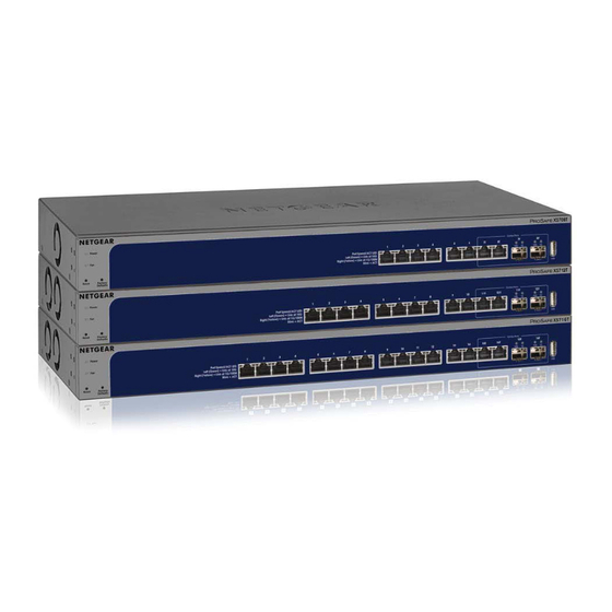
NETGEAR XS708T User Manual
8-port, 12-port, and 16-port
10-gigabit smart managed pro switch
Hide thumbs
Also See for XS708T:
- Hardware installation manual (32 pages) ,
- Installation manual (2 pages) ,
- Installation (2 pages)

Related Manuals for NETGEAR XS708T


Summary of Contents for NETGEAR XS708T
- Page 1 8-Port, 12-Port, and 16-Port 10-Gigabit Smart Managed Pro Switch M o d e l s X S 7 0 8 T, X S 7 1 2 T v 2 , a n d X S 7 1 6 T Us e r Manual August 2017 202-11652-02 350 East Plumeria Drive...
- Page 2 Thank you for purchasing this NETGEAR product. You can visit www.netgear.com/support to register your product, get help, access the latest downloads and user manuals, and join our community. We recommend that you use only official NETGEAR support resources. Conformity For the current EU Declaration of Conformity, visit http://kb.netgear.com/app/answers/detail/a_id/11621.
-
Page 3: Table Of Contents
Contents Chapter 1 Get Started Switch Management Interface Overview ....... 10 Change the Default IP Address of the Switch . - Page 4 XS708T, XS712Tv2, and XS716T Smart Managed Pro Switch User Manual View the Supported MIBs ......... . 80 Configure SNMP V3 Users.
- Page 5 XS708T, XS712Tv2, and XS716T Smart Managed Pro Switch User Manual View STP Statistics ..........163 Configure Multicast.
- Page 6 XS708T, XS712Tv2, and XS716T Smart Managed Pro Switch User Manual View the IPv6 Route Table......... 218 IPv6 Route Preferences .
- Page 7 XS708T, XS712Tv2, and XS716T Smart Managed Pro Switch User Manual Configure Port Authentication ........291 Configure Global 802.1X Settings .
- Page 8 XS708T, XS712Tv2, and XS716T Smart Managed Pro Switch User Manual Export a File From the Switch ........387 Export a File to a TFTP Server .
-
Page 9: Chapter 1 Get Started
Get Started This manual describes how you can configure and operate the NETGEAR 8-Port, 12-Port, and 16-Port 10-Gigabit Smart Managed Pro Switch Models XS708T, XS712Tv2, and XS716T by using the web-based management interface. The manual describes the software configuration procedures and explains the options that are available within those procedures. -
Page 10: Switch Management Interface Overview
Windows-based computer and is included on the resource CD. You can also download the SCC program from downloadcenter.netgear.com. If you do not use a Windows-based computer, get the IP address of the switch from the DHCP server in the network or use an IP scanner utility. -
Page 11: Discover A Switch In A Network With A Dhcp Server
XS708T, XS712Tv2, and XS716T Smart Managed Pro Switch User Manual Discover a Switch in a Network With a DHCP Server This section describes how to set up your switch in a network that includes a DHCP server. The DHCP client on the switch is enabled by default. When you connect the switch to your network, the DHCP server automatically assigns an IP address to the switch. -
Page 12: Discover A Switch In A Network Without A Dhcp Server
XS708T, XS712Tv2, and XS716T Smart Managed Pro Switch User Manual The Smart Control Center launches a browser that displays the login page of the selected device. Use your web browser to manage your switch. The default password is password. For... -
Page 13: Configure The Network Settings On Your Computer
XS708T, XS712Tv2, and XS716T Smart Managed Pro Switch User Manual Type your password to continue with the configuration change. Tip: You must enter the current password each time that you use the Smart Control Center to update the switch settings. The default password is password. - Page 14 XS708T, XS712Tv2, and XS716T Smart Managed Pro Switch User Manual To modify the network settings on your computer: Open the Control Panel and click the Network and Sharing Center option. Click the Local Area Connection link. The Local Area Connection Status pop-window opens.
- Page 15 XS708T, XS712Tv2, and XS716T Smart Managed Pro Switch User Manual WARNING: When you change the IP address of your administrative system, you lose your connection to the rest of the network. Be sure to write down your current network address settings before you change them.
-
Page 16: Access The Web Browser-Based Management Interface
XS708T, XS712Tv2, and XS716T Smart Managed Pro Switch User Manual Access the Web Browser–Based Management Interface You must be able to ping the IP address of the switch from your administrative system for web access to be available. If you used the Smart Control Center to set up the IP address and subnet mask, either with or without a DHCP server, use that IP address in the address field of your web browser. -
Page 17: Supported Web Browsers
XS708T, XS712Tv2, and XS716T Smart Managed Pro Switch User Manual Supported Web Browsers The following browsers were tested and support the web browser–based management interface. Later browser versions might function fine but were not tested. The supported web browsers include the following: •... -
Page 18: Navigation Tabs, Configuration Menus, And Page Menu
XS708T, XS712Tv2, and XS716T Smart Managed Pro Switch User Manual Help link Navigation tab Configuration menus Logout button Help page Buttons Page menu Configuration status and options Navigation Tabs, Configuration Menus, and Page Menu The navigation tabs along the top of the web interface give you quick access to the various switch functions. -
Page 19: Configuration And Status Options
XS708T, XS712Tv2, and XS716T Smart Managed Pro Switch User Manual Configuration and Status Options The area directly under the configuration menus and to the right of the links displays the configuration information or status for the page you select. On pages that contain configuration options, you might be able to enter information into fields, select options from menus, select check boxes, and select radio buttons. -
Page 20: Web Browser-Based Management Interface Device View
XS708T, XS712Tv2, and XS716T Smart Managed Pro Switch User Manual Web Browser–Based Management Interface Device View The Device View is a Java applet that displays the ports on the switch. This graphic tool ® provides an alternate way to navigate to configuration and monitoring options. The graphic tool also provides information about device ports, configuration and status, tables, and feature components. -
Page 21: Interface Naming Conventions
XS708T, XS712Tv2, and XS716T Smart Managed Pro Switch User Manual You can select a menu option to access the page that contains the configuration or monitoring options. If you right-click the graphic, but do not right-click a specific port, the main menu displays. -
Page 22: Configure Interface Settings
XS708T, XS712Tv2, and XS716T Smart Managed Pro Switch User Manual The following table describes the naming convention for all interfaces available on the switch. Table 3. Naming conventions for interfaces Interface Description Example Physical The physical ports are 10 Gigabit... - Page 23 XS708T, XS712Tv2, and XS716T Smart Managed Pro Switch User Manual The procedures in this section describe how to select the ports and LAGs to configure. The procedures assume that you are already logged in to the switch. If you do not know how to...
- Page 24 XS708T, XS712Tv2, and XS716T Smart Managed Pro Switch User Manual To configure a single port: Ensure that the page is displaying all ports, and not only the LAGs. Select the check box next to the port number. The row for the selected interface is highlighted, and the interface number appears in the heading row.
- Page 25 XS708T, XS712Tv2, and XS716T Smart Managed Pro Switch User Manual To configure multiple LAGs: Click the LAGS link or the All link to display the LAGs. Select the check box next to each LAG to configure. The check box associated with each interface is selected, and the row for each selected interface is highlighted.
-
Page 26: Context-Sensitive Help And Access To The Support Website
XS708T, XS712Tv2, and XS716T Smart Managed Pro Switch User Manual To configure multiple ports and LAGs: Click the All link to display all ports and LAGs. Select the check box associated with each port and LAG to configure. The rows for the selected ports and LAGs are highlighted. -
Page 27: User Guide
The Support page displays. To access the NETGEAR support site for the switch, click the Apply button. User Guide The user manual (the guide you are now reading) is available at the NETGEAR download center at downloadcenter.netgear.com. To access the user manual online from the web browser–based management interface: Connect your computer to the same network as the switch. -
Page 28: Register Your Product
We never sell or rent your email address and you can opt out of communications at any time. To register with NETGEAR when you are prompted, click the REGISTER NOW button. Or at any time you can visit the NETGEAR website for registration at https://my.netgear.com/registration/login.aspx. -
Page 29: Chapter 2 Configure System Information
Configure System Information This chapter covers the following topics: • View and Configure the Switch Management Settings • Use the Device View • Configure SNMP • Configure LLDP • Configure DHCP L2 Relay, DHCP Snooping, and Dynamic ARP Inspection... -
Page 30: View And Configure The Switch Management Settings
XS708T, XS712Tv2, and XS716T Smart Managed Pro Switch User Manual View and Configure the Switch Management Settings This section describes how to display the switch status and specify some basic switch information, such as the management interface IP address, system clock settings, and DNS information. - Page 31 XS708T, XS712Tv2, and XS716T Smart Managed Pro Switch User Manual Define the following fields: • System Name. Enter the name to identify this switch. You can use up to 255 alphanumeric characters. The default is blank. • System Location. Enter the location of this switch. You can use up to 255 alphanumeric characters.
- Page 32 XS708T, XS712Tv2, and XS716T Smart Managed Pro Switch User Manual View the Temperature Sensor Information You can view the current temperature of the temperature sensors. The temperature is instant and can be updated with the latest information about the switch when you click the Update button.
- Page 33 XS708T, XS712Tv2, and XS716T Smart Managed Pro Switch User Manual To view the fan status: Connect your computer to the same network as the switch. You can use a WiFi or wired connection to connect your computer to the network, or connect directly to a switch that is off-network using an Ethernet cable.
- Page 34 XS708T, XS712Tv2, and XS716T Smart Managed Pro Switch User Manual Launch a web browser. In the address field of your web browser, enter the IP address of the switch. If you do not know the IP address of the switch, see...
-
Page 35: View The System Cpu Status
XS708T, XS712Tv2, and XS716T Smart Managed Pro Switch User Manual The default password is password. The System Information page displays. Scroll down to the Versions section. To refresh the page, click the Update button. The following table describes the nonconfigurable information displayed in the Versions section of the System Information page. - Page 36 XS708T, XS712Tv2, and XS716T Smart Managed Pro Switch User Manual The CPU Utilization section shows the memory information, task-related information, and percentage of CPU utilization per task. The following table describes CPU Memory Status information. Table 9. CPU Memory Status information...
-
Page 37: View Usb Device Information
XS708T, XS712Tv2, and XS716T Smart Managed Pro Switch User Manual The login window opens. Enter the switch’s password in the Password field. The default password is password. The System Information page displays. Select System > Management > System CPU Status > CPU Threshold. - Page 38 XS708T, XS712Tv2, and XS716T Smart Managed Pro Switch User Manual To display the USB device information: Connect your computer to the same network as the switch. You can use a WiFi or wired connection to connect your computer to the network, or connect directly to a switch that is off-network using an Ethernet cable.
-
Page 39: Ip Configuration
XS708T, XS712Tv2, and XS716T Smart Managed Pro Switch User Manual The following table describes the USB Memory Statistics information. Table 10. USB Memory Statistics information Field Description Total Size The USB flash device storage size in bytes. Bytes Used The size of memory used on the USB flash device. - Page 40 XS708T, XS712Tv2, and XS716T Smart Managed Pro Switch User Manual Select the appropriate radio button to determine how to configure the network information for the switch management interface: • Dynamic IP Address (DHCP). Specifies that the switch must obtain the IP address through a DHCP server.
-
Page 41: Ipv6 Network Configuration
XS708T, XS712Tv2, and XS716T Smart Managed Pro Switch User Manual The updated configuration is sent to the switch. Configuration changes take effect immediately. IPv6 Network Configuration Use the IPv6 Network Configuration page to configure the IPv6 network interface, which is the logical interface used for in-band connectivity with the switch through all of the switch’s... -
Page 42: View The Ipv6 Network Neighbor
XS708T, XS712Tv2, and XS716T Smart Managed Pro Switch User Manual • DHCPv6. Next to Current Network Configuration Protocol, select the DHCPv6 radio button to enable the DHCPv6 client on the interface. The switch attempts to acquire network information from a DHCPv6 server. Selecting the None radio button disables the DHCPv6 client on the network interface. -
Page 43: Configure The Time Settings
XS708T, XS712Tv2, and XS716T Smart Managed Pro Switch User Manual Click the Clear button to clear the neighbor information and refresh the page to show the latest neighbor information. Click the Update button to update the page and show the latest neighbor information. - Page 44 XS708T, XS712Tv2, and XS716T Smart Managed Pro Switch User Manual Launch a web browser. In the address field of your web browser, enter the IP address of the switch. If you do not know the IP address of the switch, see...
- Page 45 XS708T, XS712Tv2, and XS716T Smart Managed Pro Switch User Manual Enter the switch’s password in the Password field. The default password is password. The System Information page displays. Select System > Management > Time > Time Configuration. The Time Configuration page displays.
- Page 46 XS708T, XS712Tv2, and XS716T Smart Managed Pro Switch User Manual The allowed range is 1 to 30. The default value is 5. In the Unicast Poll Retry field, specify the number of times to retry a unicast poll request to an SNTP server after the first time-out before the switch attempts to use the next configured server.
- Page 47 XS708T, XS712Tv2, and XS716T Smart Managed Pro Switch User Manual The System Information page displays. Select System > Management > Time > Time Configuration > SNTP Global Configuration. When you select the SNTP option as the clock source, the SNTP Global Configuration section is displayed below the Time Configuration section of the page.
- Page 48 XS708T, XS712Tv2, and XS716T Smart Managed Pro Switch User Manual Broadcasts received prior to the expiry of this interval are discarded. The allowed range is 6 to 10. The default value is 6. In the Unicast Poll Timeout field, specify the number of seconds to wait for an SNTP response to a unicast poll request.
- Page 49 XS708T, XS712Tv2, and XS716T Smart Managed Pro Switch User Manual In the address field of your web browser, enter the IP address of the switch. If you do not know the IP address of the switch, see Change the Default IP Address of the Switch on page 10.
- Page 50 XS708T, XS712Tv2, and XS716T Smart Managed Pro Switch User Manual Table 13. SNTP Global Status information (continued) Field Description Last Attempt Status The status of the last SNTP request or unsolicited message for both unicast and broadcast modes. If no message was received from a server, a status of Other is displayed.
- Page 51 XS708T, XS712Tv2, and XS716T Smart Managed Pro Switch User Manual The following is an example of strata: • Stratum 0. A real-time clock is used as the time source, for example, a GPS system. • Stratum 1. A server that is directly linked to a Stratum 0 time source is used. Stratum 1 time servers provide primary network time standards.
- Page 52 XS708T, XS712Tv2, and XS716T Smart Managed Pro Switch User Manual The System Information page displays. Select System > Management > Time > SNTP Server Configuration. From the Server Type menu, select the type of SNTP address to enter in the address field.
- Page 53 XS708T, XS712Tv2, and XS716T Smart Managed Pro Switch User Manual The SNTP Server Status table displays status information about the SNTP servers configured on your switch. The following table describes the SNTP Server Global Status information. Table 14. SNTP Server Status information...
- Page 54 XS708T, XS712Tv2, and XS716T Smart Managed Pro Switch User Manual The default password is password. The System Information page displays. Select System > Management > Time > SNTP Server Configuration. The SNTP Server Configuration page displays. Select the check box next to the configured server.
- Page 55 XS708T, XS712Tv2, and XS716T Smart Managed Pro Switch User Manual To configure the daylight saving time settings: Connect your computer to the same network as the switch. You can use a WiFi or wired connection to connect your computer to the network, or connect directly to a switch that is off-network using an Ethernet cable.
- Page 56 XS708T, XS712Tv2, and XS716T Smart Managed Pro Switch User Manual The updated configuration is sent to the switch. Configuration changes take effect immediately. The fields in the following tables are visible only when the DayLight Saving (DST) Recurring, Recurring EU, or Recurring USA radio button is selected.
- Page 57 XS708T, XS712Tv2, and XS716T Smart Managed Pro Switch User Manual Table 16. Daylight saving setting is Non Recurring (continued) Field Description Offset Specify the number of minutes to shift the summer time from the standard time. The valid range is 1–1440 minutes.
-
Page 58: Configure Denial Of Service Settings
XS708T, XS712Tv2, and XS716T Smart Managed Pro Switch User Manual The following table displays the nonconfigurable daylight saving status information. Table 17. Daylight Saving (DST) Status information Field Description Daylight Saving (DST) The Daylight Saving value, which is one of the following: •... - Page 59 XS708T, XS712Tv2, and XS716T Smart Managed Pro Switch User Manual The default password is password. The System Information page displays. Select System > Management > Denial of Service > Auto-DoS Configuration. The Auto-DoS Configuration page displays. Next to Auto-DoS Mode, select the Enable radio button.
- Page 60 XS708T, XS712Tv2, and XS716T Smart Managed Pro Switch User Manual Select the types of DoS attacks for the switch to monitor and block and configure any associated values: • Denial of Service Min TCP Header Size. Specify the minimum TCP header size allowed.
-
Page 61: Configure Dns Settings
XS708T, XS712Tv2, and XS716T Smart Managed Pro Switch User Manual • Denial of Service SMAC=DMAC. Enabling SMAC=DMAC DoS prevention causes the switch to drop packets with a source MAC address equal to the destination MAC address. • Denial of Service TCP FIN&URG&PSH. Enabling TCP FIN & URG & PSH DoS prevention causes the switch to drop packets with TCP Flags FIN, URG, and PSH set and TCP sequence number equal to 0. - Page 62 When the system is performing a lookup on an unqualified host name, this field is provides the domain name (for example, if default domain name is netgear.com and the user enters test, then test is changed to test.netgear.com to resolve the name). The name must not be longer than 255 characters.
- Page 63 XS708T, XS712Tv2, and XS716T Smart Managed Pro Switch User Manual The updated configuration is sent to the switch. Configuration changes take effect immediately. To refresh the page, click the Update button. The following table displays DNS Server Configuration information. Table 18. DNS Server Configuration information...
- Page 64 XS708T, XS712Tv2, and XS716T Smart Managed Pro Switch User Manual Its length cannot exceed 255 characters and it is a required field. In the IPv4/IPv6 Address field, enter the IP address to associate with the host name. Click the Add button.
-
Page 65: Configure Green Ethernet Settings
XS708T, XS712Tv2, and XS716T Smart Managed Pro Switch User Manual Enter the switch’s password in the Password field. The default password is password. The System Information page displays. Select System > Management > DNS > Host Configuration. The DNS Host Configuration page display. - Page 66 XS708T, XS712Tv2, and XS716T Smart Managed Pro Switch User Manual The default password is password. The System Information page displays. Select System > Management > Green Ethernet > Green Ethernet Configuration. Select the EEE Mode Disable or Enable radio button.
- Page 67 XS708T, XS712Tv2, and XS716T Smart Managed Pro Switch User Manual Do one of the following: • In the Go To Interface field, enter the port using the respective naming convention (for example, xg1 or l1), and click the Go button.
- Page 68 XS708T, XS712Tv2, and XS716T Smart Managed Pro Switch User Manual The default password is password. The System Information page displays. Select System > Management > Green Ethernet > Green Ethernet Details. From the Interface menu, select the interface. Use the EEE Admin mode menu to enable or disable this option on the port.
- Page 69 XS708T, XS712Tv2, and XS716T Smart Managed Pro Switch User Manual The following table describes the nonconfigurable fields. Table 20. Green Ethernet Local Device Information Field Description Cumulative Energy Saved on this Cumulative energy saved due to all green modes enabled on this port port due to Green mode(s) (Watts in watts * hours.
- Page 70 XS708T, XS712Tv2, and XS716T Smart Managed Pro Switch User Manual View Green Ethernet Remote Device Details To view green Ethernet remote device information: Connect your computer to the same network as the switch. You can use a WiFi or wired connection to connect your computer to the network, or connect directly to a switch that is off-network using an Ethernet cable.
- Page 71 XS708T, XS712Tv2, and XS716T Smart Managed Pro Switch User Manual View the Green Ethernet Statistics Summary This page summarizes the green Ethernet settings currently in use. To view the green Ethernet statistics: Connect your computer to the same network as the switch.
- Page 72 XS708T, XS712Tv2, and XS716T Smart Managed Pro Switch User Manual The following table describes the nonconfigurable fields. Table 22. Green Ethernet Statistics Summary information Field Description Current Power Consumption by all Estimated Power Consumption by all ports in chassis in mWatts.
- Page 73 XS708T, XS712Tv2, and XS716T Smart Managed Pro Switch User Manual If you do not know the IP address of the switch, see Change the Default IP Address of the Switch on page 10. The login window opens. Enter the switch’s password in the Password field.
-
Page 74: Use The Device View
XS708T, XS712Tv2, and XS716T Smart Managed Pro Switch User Manual Table 23. Interface Green Mode EEE LPI History information (continued) Field Description Percentage Time spent in LPI Percentage of time spent in LPI mode during the current measurement mode since last sample interval. - Page 75 XS708T, XS712Tv2, and XS716T Smart Managed Pro Switch User Manual The default password is password. The System Information page displays. Select System > SNMP > SNMP V1/V2 > Community Configuration. In the Management Station IP field, specify the IP address of the management station.
- Page 76 XS708T, XS712Tv2, and XS716T Smart Managed Pro Switch User Manual If you do not know the IP address of the switch, see Change the Default IP Address of the Switch on page 10. The login window opens. Enter the switch’s password in the Password field.
-
Page 77: Configure Snmpv1/V2 Trap Settings
XS708T, XS712Tv2, and XS716T Smart Managed Pro Switch User Manual Configure SNMPv1/v2 Trap Settings You can configure settings for each SNMPv1 or SNMPv2 management host that must receive notifications about traps generated by the device. The SNMP management host is also known as the SNMP trap receiver. - Page 78 XS708T, XS712Tv2, and XS716T Smart Managed Pro Switch User Manual Modify Information About an Existing SNMP Recipient To modify information about an existing SNMP recipient: Connect your computer to the same network as the switch. You can use a WiFi or wired connection to connect your computer to the network, or connect directly to a switch that is off-network using an Ethernet cable.
-
Page 79: Configure Snmpv1/V2 Trap Flags
XS708T, XS712Tv2, and XS716T Smart Managed Pro Switch User Manual The Trap Configuration page displays. Select the check box next to the recipient to remove. Click the Delete button. The trap recipient is removed. Configure SNMPv1/v2 Trap Flags Use the Trap Flags page to enable or disable traps the switch can send to an SNMP manager. -
Page 80: View The Supported Mibs
XS708T, XS712Tv2, and XS716T Smart Managed Pro Switch User Manual • Link Up/Down. When enabled, SNMP traps are sent when the administrative or operational state of a physical or logical link changes. The default is Enable. • Spanning Tree. When enabled, SNMP traps are sent when various spanning tree events occur. -
Page 81: Configure Snmp V3 Users
XS708T, XS712Tv2, and XS716T Smart Managed Pro Switch User Manual The following table describes the SNMP Supported MIBs Status fields. Table 24. SNMP supported MIBs Field Description Name The RFC number if applicable and the name of the MIB. Description The RFC title or MIB description. -
Page 82: Configure Lldp
XS708T, XS712Tv2, and XS716T Smart Managed Pro Switch User Manual b. In the Encryption Key field, enter an encryption code of eight or more alphanumeric characters. Click the Apply button. The updated configuration is sent to the switch. Configuration changes take effect immediately. -
Page 83: Configure Lldp Global Settings
XS708T, XS712Tv2, and XS716T Smart Managed Pro Switch User Manual Configure LLDP Global Settings Use the LLDP Configuration page to specify the global LLDP and LLDP-MED parameters that are applied to the switch. To configure global LLDP settings: Connect your computer to the same network as the switch. -
Page 84: Configure Lldp Port Settings
XS708T, XS712Tv2, and XS716T Smart Managed Pro Switch User Manual This value sets the number of LLDP packets sent when the LLDP-MED fast start mechanism is initialized, which occurs when a new endpoint device links with the LLDP-MED network connectivity device. -
Page 85: Lldp-Med Network Policy
XS708T, XS712Tv2, and XS716T Smart Managed Pro Switch User Manual • To configure all interfaces with the same settings, select the check box in the heading row. Use the following menus to configure the LLDP settings for the selected ports: •... - Page 86 XS708T, XS712Tv2, and XS716T Smart Managed Pro Switch User Manual If you do not know the IP address of the switch, see Change the Default IP Address of the Switch on page 10. The login window opens. Enter the switch’s password in the Password field.
-
Page 87: Lldp-Med Port Settings
XS708T, XS712Tv2, and XS716T Smart Managed Pro Switch User Manual LLDP-MED Port Settings Use this page to enable LLDP-MED mode on an interface and configure its properties. To configure LLDP-MED settings for a port: Connect your computer to the same network as the switch. -
Page 88: Lldp-Med Neighbors Information
XS708T, XS712Tv2, and XS716T Smart Managed Pro Switch User Manual LLDP-MED Neighbors Information Use this page to display the LLDP-MED neighbor or remote device information on an interface. To view LLDP-MED Neighbor Information: Connect your computer to the same network as the switch. - Page 89 XS708T, XS712Tv2, and XS716T Smart Managed Pro Switch User Manual The following table describes the non-configurable LLDP-MED Neighbors Information that displays for the selected interface. Field Description LLDP-MED Interface Selection Remote ID Specifies the remote client identifier assigned to the remote system.
-
Page 90: Local Information
XS708T, XS712Tv2, and XS716T Smart Managed Pro Switch User Manual Field Description Location Information This section of the page specifies if location TLV is received in LLDP frames on this port. Sub Type Specifies the type of location information. Location Information Specifies the location information as a string for a given type of location ID. - Page 91 XS708T, XS712Tv2, and XS716T Smart Managed Pro Switch User Manual The login window opens. Enter the switch’s password in the Password field. The default password is password. The System Information page displays. Select System > Advanced > LLDP > Local Information.
- Page 92 XS708T, XS712Tv2, and XS716T Smart Managed Pro Switch User Manual The following table describes the detailed local information that displays for the selected port. Field Description Managed Address Address SubType The type of address the management interface uses, such as an IPv4 address.
-
Page 93: Neighbors Information
XS708T, XS712Tv2, and XS716T Smart Managed Pro Switch User Manual Neighbors Information Use the LLDP Neighbors Information page to view the data that a specified interface received from other LLDP-enabled systems. To view LLDP information received from a neighbor device: Connect your computer to the same network as the switch. - Page 94 XS708T, XS712Tv2, and XS716T Smart Managed Pro Switch User Manual Field Description Chassis ID The remote 802 LAN device’s chassis. Port ID Subtype The type of data displayed in the remote system’s Port ID field. Port ID The physical address of the port on the remote system from which the data was sent.
- Page 95 XS708T, XS712Tv2, and XS716T Smart Managed Pro Switch User Manual Field Description MAC/PHY Details Auto-Negotiation Supported Specifies whether the remote device supports port-speed autonegotiation. The possible values are True or False. Auto-Negotiation Enabled The port speed autonegotiation support status. The possible values are True and False.
-
Page 96: Configure Dhcp L2 Relay, Dhcp Snooping, And Dynamic Arp Inspection
XS708T, XS712Tv2, and XS716T Smart Managed Pro Switch User Manual Field Description Network Policies Application Type The media application type associated with the policy advertised by the remote device. VLAN ID The VLAN ID associated with the policy. VLAN Type Specifies whether the VLAN associated with the policy is tagged or untagged. - Page 97 XS708T, XS712Tv2, and XS716T Smart Managed Pro Switch User Manual DHCP L2 Relay Global Configuration Use this page to view and configure the global settings for DHCP snooping. To enable DHCP L2 Relay global settings: Connect your computer to the same network as the switch.
- Page 98 XS708T, XS712Tv2, and XS716T Smart Managed Pro Switch User Manual DHCP L2 Relay Interface Configuration Use this page to view and configure the DHCP L2 relay interface. To configure DHCP L2 relay interface settings: Connect your computer to the same network as the switch.
- Page 99 XS708T, XS712Tv2, and XS716T Smart Managed Pro Switch User Manual Click the Apply button. The updated configuration is sent to the switch. Configuration changes take effect immediately. DHCP L2 Relay Interface Statistics The DHCP L2 Relay Interface Statistics table shows information about the DHCP L2 relay interface.
-
Page 100: Dhcp Snooping
XS708T, XS712Tv2, and XS716T Smart Managed Pro Switch User Manual Field Description Trusted Server Messages The number of DHCP message without option82 received from a trusted server. Without Opt82 Trusted Client Messages The number of DHCP message without option82 received from a trusted client. - Page 101 XS708T, XS712Tv2, and XS716T Smart Managed Pro Switch User Manual Next to DHCP Snooping Mode, select the Enable radio button. To enable the verification of the sender’s MAC address for DHCP snooping, next to MAC Address Validation, select the Enable radio button.
-
Page 102: Interface Configuration
XS708T, XS712Tv2, and XS716T Smart Managed Pro Switch User Manual The updated configuration is sent to the switch. Configuration changes take effect immediately. Interface Configuration Use the DHCP Snooping Interface Configuration page to view and configure each port as a trusted or untrusted port. - Page 103 XS708T, XS712Tv2, and XS716T Smart Managed Pro Switch User Manual From the Trust Mode menu, select the desired trust mode: • Disabled. The interface is considered to be untrusted and could potentially be used to launch a network attack. DHCP server messages are checked against the bindings database.
- Page 104 XS708T, XS712Tv2, and XS716T Smart Managed Pro Switch User Manual The login window opens. Enter the switch’s password in the Password field. The default password is password. The System Information page displays. Select System> Services > DHCP Snooping > Binding Configuration.
-
Page 105: Persistent Configuration
XS708T, XS712Tv2, and XS716T Smart Managed Pro Switch User Manual Persistent Configuration Use this page to configure the persistent location of the DHCP snooping bindings database. The bindings database can be stored locally on the device or on a remote system somewhere else in the network. - Page 106 XS708T, XS712Tv2, and XS716T Smart Managed Pro Switch User Manual Click the Apply button. The updated configuration is sent to the switch. Configuration changes take effect immediately. Statistics Use this page to view and clear per-interface statistics about the DHCP messages filtered by the DHCP snooping feature on untrusted interfaces.
-
Page 107: Dynamic Arp Inspection
XS708T, XS712Tv2, and XS716T Smart Managed Pro Switch User Manual The following table describes the DHCP snooping statistics. Table 27. DHCP Snooping Statistics information Field Description Interface The interface associated with the rest of the data in the row. MAC Verify Failures The number of DHCP messages that were dropped because the source MAC address and client hardware address did not match. - Page 108 XS708T, XS712Tv2, and XS716T Smart Managed Pro Switch User Manual The valid IP check is applied only on the sender IP address in ARP packets. In ARP response packets, the check is applied only on the target IP address. ...
- Page 109 XS708T, XS712Tv2, and XS716T Smart Managed Pro Switch User Manual This example assumes that VLAN 1 and LAG 1 are already configured. To enable DAI on a VLAN1: Connect your computer to the same network as the switch. You can use a WiFi or wired connection to connect your computer to the network, or connect directly to a switch that is off-network using an Ethernet cable.
- Page 110 XS708T, XS712Tv2, and XS716T Smart Managed Pro Switch User Manual A VLAN can be configured to use this ARP ACL containing rules as the filter for ARP packet validation. The name can be 1 to 31 alphanumeric characters. The ARP ACL name is deleted if you specify N/A.
- Page 111 XS708T, XS712Tv2, and XS716T Smart Managed Pro Switch User Manual Next to l1, select the check box. From the Trust Mode menu, select Enable to indicate that the interface is trusted. The Trust Mode field indicates whether the interface is trusted for dynamic ARP inspection purposes.
- Page 112 XS708T, XS712Tv2, and XS716T Smart Managed Pro Switch User Manual Configure a DAI ACL DAI relies on the information in the DHCP snooping bindings database to validate ARP packets. For networks that use static IP addresses and do not use DHCP, DAI access control lists (ACLs) can be used to statically map an IP address to a MAC address on a VLAN.
- Page 113 XS708T, XS712Tv2, and XS716T Smart Managed Pro Switch User Manual Click the ACL name. The ACL name is a hyperlink to the Dynamic ARP Inspection ACL Rule Configuration page. From the ACL Name menu, select the DAI ACL to configure.
- Page 114 XS708T, XS712Tv2, and XS716T Smart Managed Pro Switch User Manual Next to VLAN 1, select the check box. In the ARP ACL Name field, specify the name of the DAI ACL to associate with the VLAN. For example, enter arpACL.
- Page 115 XS708T, XS712Tv2, and XS716T Smart Managed Pro Switch User Manual The following table describes the nonconfigurable DAI statistics information that is displayed. Field Description VLAN The enabled VLAN ID for which statistics are displayed. DHCP Drops The number of ARP packets that were dropped by DAI because no matching DHCP snooping binding entry was found.
-
Page 116: Chapter 3 Configure Switching
Configure Switching This chapter covers the following topics: • Configure Port Settings • Configure Link Aggregation Groups • Configure VLANs • Configure Auto-VoIP • Configure Spanning Tree Protocol • Configure Multicast • Configure Multicast VLAN Registration • View and Configure the MAC Address Table... -
Page 117: Configure Port Settings
XS708T, XS712Tv2, and XS716T Smart Managed Pro Switch User Manual Configure Port Settings You can view, configure, and monitor the physical port information for the ports (that is, the physical interfaces) on the switch. Flow control helps to prevent data loss when the port cannot keep up with the number of frames being switched. - Page 118 XS708T, XS712Tv2, and XS716T Smart Managed Pro Switch User Manual This sets the port control administrative mode. You must select Enable in order for the port to participate in the network. The default is Enable. From the Auto-negotiation menu, select Enable or Disable.
-
Page 119: Configure Link Aggregation Groups
XS708T, XS712Tv2, and XS716T Smart Managed Pro Switch User Manual From the Flow Control menu, select one of the following options: • Disable. The switch cannot receive pause frames for the port nor does it send pause frames if incoming traffic on the port is congested (that is, the port buffers are full). -
Page 120: Configure Lag Settings
XS708T, XS712Tv2, and XS716T Smart Managed Pro Switch User Manual A LAG interface can be either static or dynamic, but not both. All members of a LAG must participate in the same protocols. A static port channel interface does not require a partner system to be able to aggregate its member ports. - Page 121 XS708T, XS712Tv2, and XS716T Smart Managed Pro Switch User Manual From the Hash Mode menu, select the load balancing mode for the LAG. Traffic is balanced on the LAG through one of the links in the channel over which packets are transmitted.
-
Page 122: Configure Lag Membership
XS708T, XS712Tv2, and XS716T Smart Managed Pro Switch User Manual Configure LAG Membership You can select two or more full-duplex Ethernet links to be aggregated together to form a link aggregation group (LAG), which is also known as a port channel. The switch can treat the port channel as a single link. -
Page 123: Set The Lacp System Priority
XS708T, XS712Tv2, and XS716T Smart Managed Pro Switch User Manual Set the LACP System Priority The LACP configuration page is used to set the LACP system priority. To configure LACP: Connect your computer to the same network as the switch. -
Page 124: Set The Lacp Port Priority Settings
XS708T, XS712Tv2, and XS716T Smart Managed Pro Switch User Manual Set the LACP Port Priority Settings The LACP port configuration page is used to configure the LACP priority value for the selected port and the administrative LACP time-out value. ... -
Page 125: Configure Vlans
XS708T, XS712Tv2, and XS716T Smart Managed Pro Switch User Manual In the Timeout field, configure the administrative LACP time-out value: • Long. Specifies a long time-out value. • Short. Specifies a short time-out value. Click the Apply button. The updated configuration is sent to the switch. Configuration changes take effect immediately. - Page 126 XS708T, XS712Tv2, and XS716T Smart Managed Pro Switch User Manual If you do not know the IP address of the switch, see Change the Default IP Address of the Switch on page 10. The login window opens. Enter the switch’s password in the Password field.
- Page 127 XS708T, XS712Tv2, and XS716T Smart Managed Pro Switch User Manual In the address field of your web browser, enter the IP address of the switch. If you do not know the IP address of the switch, see Change the Default IP Address of the Switch on page 10.
-
Page 128: Configure Vlan Membership
XS708T, XS712Tv2, and XS716T Smart Managed Pro Switch User Manual Click the Apply button. The updated configuration is sent to the switch. Configuration changes take effect immediately. The default values are as follows: • All ports are assigned to the default VLAN of 1. - Page 129 XS708T, XS712Tv2, and XS716T Smart Managed Pro Switch User Manual In the VLAN ID menu, select the VLAN ID. In the Group Operation menu, select one of the following options, which applies to all ports in the VLAN: • Untag All. For all ports that are members of the VLAN, tags are removed from all egress packets.
-
Page 130: View Vlan Status
XS708T, XS712Tv2, and XS716T Smart Managed Pro Switch User Manual The following table describes the nonconfigurable information displayed on the page. Table 30. Advanced VLAN membership Field Definition VLAN Name The name for the VLAN that you selected. It can be up to 32 alphanumeric characters long, including blanks. -
Page 131: Configure Port Pvid Settings
XS708T, XS712Tv2, and XS716T Smart Managed Pro Switch User Manual The following table describes the nonconfigurable information displayed on the page. Table 31. VLAN status Field Definition VLAN ID The VLAN identifier (VID) of the VLAN. The range of the VLAN ID is 1 to 4093. - Page 132 XS708T, XS712Tv2, and XS716T Smart Managed Pro Switch User Manual To display information for all physical ports and LAGs, click ALL. Select interfaces by selecting the Interface check boxes next to the interfaces. You can select multiple interfaces. To select all the interfaces, select the Interface check box in the heading row.
-
Page 133: Configure A Mac-Based Vlan
XS708T, XS712Tv2, and XS716T Smart Managed Pro Switch User Manual Click the Apply button. The updated configuration is sent to the switch. Configuration changes take effect immediately. The following table describes the nonconfigurable fields. Table 32. Nonconfigurable fields on the PVID Configuration page... - Page 134 XS708T, XS712Tv2, and XS716T Smart Managed Pro Switch User Manual Enter the switch’s password in the Password field. The default password is password. The System Information page displays. Select Switching> VLAN > Advanced > MAC Based VLAN. In the MAC Address field, enter a valid MAC address to be bound to a VLAN ID.
-
Page 135: Configure Protocol-Based Vlan Groups
XS708T, XS712Tv2, and XS716T Smart Managed Pro Switch User Manual Configure Protocol-Based VLAN Groups You can use a protocol-based VLAN to define filtering criteria for untagged packets. By default, if you do not configure any port-based (IEEE 802.1Q) or protocol-based VLANs, untagged packets are assigned to VLAN 1. -
Page 136: Configure Protocol-Based Vlan Group Membership
XS708T, XS712Tv2, and XS716T Smart Managed Pro Switch User Manual In the Protocol field, enter one or more protocols that must be associated with the group. You can enter keywords such as arp, ip, and ipx. Separate keywords with a comma. You can also enter hexadecimal or decimal values in the range of 0x0600 (1536) to 0xFFFF (65535). -
Page 137: Configure A Voice Vlan
XS708T, XS712Tv2, and XS716T Smart Managed Pro Switch User Manual From the Group ID menu, select the protocol-based VLAN group ID. The Group Name field shows the name that is associated with the group. In the Ports table and LAG table, click each port and LAG that you want to include in the protocol-based VLAN group. - Page 138 XS708T, XS712Tv2, and XS716T Smart Managed Pro Switch User Manual The default password is password. The System Information page displays. Select Switching> VLAN > Advanced > Voice VLAN Configuration. Select the Admin Mode Disable or Enable radio button. This specifies the administrative mode for the voice VLAN for the switch. The default is Disable.
-
Page 139: Configure Garp Switch Settings
XS708T, XS712Tv2, and XS716T Smart Managed Pro Switch User Manual Note: Authentication through dot1x is possible only if dot1x is enabled. In the DSCP Value field, configure the Voice VLAN DSCP value for the port. The valid range is 0 to 64. The default value is 0. -
Page 140: Configure Garp Port
XS708T, XS712Tv2, and XS716T Smart Managed Pro Switch User Manual Enter the switch’s password in the Password field. The default password is password. The System Information page displays. Select Switching> VLAN > Advanced > GARP Switch Configuration. Select the GVRP Mode Disable or Enable radio button. - Page 141 XS708T, XS712Tv2, and XS716T Smart Managed Pro Switch User Manual Select one or more interfaces by taking one of the following actions: • To configure a single interface, select the check box associated with the port, or type the port number in the Go To Interface field and click the Go button.
-
Page 142: Configure Auto-Voip
XS708T, XS712Tv2, and XS716T Smart Managed Pro Switch User Manual Configure Auto-VoIP Voice over Internet Protocol (VoIP) enables telephone calls over a data network. Because voice traffic is typically more time-sensitive than data traffic, the Auto-VoIP feature helps provide a classification mechanism for voice packets so that they can be prioritized above data packets in order to provide better Quality of Service (QoS). -
Page 143: Configure Auto-Voip Oui-Based Properties
XS708T, XS712Tv2, and XS716T Smart Managed Pro Switch User Manual From the Prioritization Type menu, select Traffic Class or Remark. This specifies the type of prioritization. From the Class Value menu, specify the CoS tag value to be reassigned for packets received on the voice VLAN when Remark CoS is enabled. -
Page 144: Oui-Based Port Settings
XS708T, XS712Tv2, and XS716T Smart Managed Pro Switch User Manual In the Auto-VoIP VLAN ID field, enter the VoIP VLAN ID of the switch. No default VLAN exists for Auto-VoIP, you must create a VLAN for Auto-VoIP. From the OUI-based priority menu, select the OUI-based priority of the switch. -
Page 145: Manage The Oui Table
XS708T, XS712Tv2, and XS716T Smart Managed Pro Switch User Manual Select one or more interfaces by taking one of the following actions: • To configure a single interface, select the check box associated with the port, or type the port number in the Go To Interface field and click the Go button. - Page 146 XS708T, XS712Tv2, and XS716T Smart Managed Pro Switch User Manual • 00:1B:4F: AVAYA2 • 00:04:13: SNOM You can select an existing OUI or add a new OUI and description to identify the IP phones on the network. Configure the OUI Table ...
- Page 147 XS708T, XS712Tv2, and XS716T Smart Managed Pro Switch User Manual The maximum length of description is 32 characters. The following OUIs are present in the configuration by default: • 00:01:E3 - SIEMENS • 00:03:6B - CISCO1 • 00:12:43 - CISCO2 •...
-
Page 148: Display The Auto-Voip Status
XS708T, XS712Tv2, and XS716T Smart Managed Pro Switch User Manual Display the Auto-VoIP Status Use this page to display Auto-VoIP status. To view the Auto-VoIP status: Connect your computer to the same network as the switch. You can use a WiFi or wired connection to connect your computer to the network, or connect directly to a switch that is off-network using an Ethernet cable. -
Page 149: Configure Spanning Tree Protocol
XS708T, XS712Tv2, and XS716T Smart Managed Pro Switch User Manual Configure Spanning Tree Protocol The Spanning Tree Protocol (STP) provides a tree topology for any arrangement of bridges. STP also provides one path between end stations on a network, eliminating loops. Spanning tree versions supported include Common STP, Multiple STP, and Rapid STP. - Page 150 XS708T, XS712Tv2, and XS716T Smart Managed Pro Switch User Manual Select Switching > STP > Basic > STP Configuration. Configure the following options: • Spanning Tree State. Enable or disable the spanning tree operation on the switch. • STP Operation Mode. Specify the STP version for the switch. The options are STP, RSTP, and MSTP.
-
Page 151: Configure Cst Settings
XS708T, XS712Tv2, and XS716T Smart Managed Pro Switch User Manual Table 35. STP configuration status (continued) Field Description Designated Root The bridge identifier of the root bridge. It is made up from the bridge priority and the base MAC address of the bridge. - Page 152 XS708T, XS712Tv2, and XS716T Smart Managed Pro Switch User Manual Specify the CST options: • Bridge Priority. When switches or bridges are running STP, each is assigned a priority. After exchanging BPDUs, the switch with the lowest priority value becomes the root bridge.
-
Page 153: Configure Cst Port Settings
XS708T, XS712Tv2, and XS716T Smart Managed Pro Switch User Manual The following table describes the MSTP Status information that is displayed. Table 36. STP advanced CST configuration, MSTP status Field Description MST ID Table consisting of the MST instances (including the CST) and the corresponding VLAN IDs associated with each of them. - Page 154 XS708T, XS712Tv2, and XS716T Smart Managed Pro Switch User Manual Select one or more interfaces by taking one of the following actions: • To configure a single interface, select the check box associated with the port, or type the port number in the Go To Interface field and click the Go button.
-
Page 155: View Cst Port Status
XS708T, XS712Tv2, and XS716T Smart Managed Pro Switch User Manual The following table describes the nonconfigurable information displayed on the page. Table 37. CST port configuration Field Description Port State The forwarding state of this port. The default is Disabled. - Page 156 XS708T, XS712Tv2, and XS716T Smart Managed Pro Switch User Manual To refresh the page with the latest information about the switch, click the Update button. The following table describes the CST Status information displayed on the page. Table 38. CST port status...
-
Page 157: View Rapid Stp Information
XS708T, XS712Tv2, and XS716T Smart Managed Pro Switch User Manual View Rapid STP Information Use the Rapid STP page to view information about Rapid Spanning Tree (RSTP) port status. To view information about RSTP: Connect your computer to the same network as the switch. -
Page 158: Manage Mst Settings
XS708T, XS712Tv2, and XS716T Smart Managed Pro Switch User Manual Manage MST Settings Use the Spanning Tree MST Configuration page to configure Multiple Spanning Tree (MST) on the switch. Configure an MST Instance To configure an MST instance: Connect your computer to the same network as the switch. - Page 159 XS708T, XS712Tv2, and XS716T Smart Managed Pro Switch User Manual For each configured instance, the information described in the following table displays on the page. Table 40. MST configuration Field Description Bridge Identifier The bridge identifier for the selected MST instance. It is made up using the bridge priority and the base MAC address of the bridge.
-
Page 160: Mst Port Configuration
XS708T, XS712Tv2, and XS716T Smart Managed Pro Switch User Manual Click the Apply button. The updated configuration is sent to the switch. Configuration changes take effect immediately. Delete an MST Instance To delete an MST instance: Connect your computer to the same network as the switch. - Page 161 XS708T, XS712Tv2, and XS716T Smart Managed Pro Switch User Manual In the address field of your web browser, enter the IP address of the switch. If you do not know the IP address of the switch, see Change the Default IP Address of the Switch on page 10.
- Page 162 XS708T, XS712Tv2, and XS716T Smart Managed Pro Switch User Manual The following table describes the read-only MST port configuration information displayed on the Spanning Tree CST Configuration page. Table 41. MST port status information Field Description Auto-calculated Port Path Displays whether the path cost is automatically calculated (Enabled) or not Cost (Disabled).
-
Page 163: View Stp Statistics
XS708T, XS712Tv2, and XS716T Smart Managed Pro Switch User Manual View STP Statistics You can view information about the number and type of bridge protocol data units (BPDUs) transmitted and received on each port. To view Spanning Tree statistics: Connect your computer to the same network as the switch. -
Page 164: Configure Multicast
XS708T, XS712Tv2, and XS716T Smart Managed Pro Switch User Manual Configure Multicast Multicast IP traffic is traffic that is destined to a host group. Host groups for IPv4 multicast are identified by class D addresses, which range from 224.0.0.0 to 239.255.255.255. Host groups for IPv6 multicast are identified by the prefix ff00::/8. -
Page 165: View The Mfdb Statistics
XS708T, XS712Tv2, and XS716T Smart Managed Pro Switch User Manual Table 43. MFDB table information Field Description MAC Address The multicast MAC address for which you requested data. VLAN ID The VLAN ID to which the multicast MAC address is related. -
Page 166: Auto-Video
XS708T, XS712Tv2, and XS716T Smart Managed Pro Switch User Manual The following table describes the MFDB Statistics fields. Table 44. MFDB Statistics information Field Description Max MFDB Table Entries The maximum number of entries that the Multicast Forwarding Database table can hold. -
Page 167: Igmp Snooping
XS708T, XS712Tv2, and XS716T Smart Managed Pro Switch User Manual IGMP Snooping Internet Group Management Protocol (IGMP) snooping is a feature that allows a switch to forward multicast traffic intelligently on the switch. Multicast IP traffic is traffic that is destined to a host group. - Page 168 XS708T, XS712Tv2, and XS716T Smart Managed Pro Switch User Manual The System Information page displays. Select Switching> Multicast > IGMP Snooping > Configuration. The previous figure does not show the VLAN IDs Enabled For IGMP Snooping section and the VLAN IDs Enabled For IGMP Snooping Querier section.
-
Page 169: Configure Igmp Snooping For Interfaces
XS708T, XS712Tv2, and XS716T Smart Managed Pro Switch User Manual Configure IGMP Snooping for Interfaces To configure IGMP snooping for interfaces: Connect your computer to the same network as the switch. You can use a WiFi or wired connection to connect your computer to the network, or connect directly to a switch that is off-network using an Ethernet cable. -
Page 170: View The Igmp Snooping Table
XS708T, XS712Tv2, and XS716T Smart Managed Pro Switch User Manual In the Max Response Time field, specify the time that the switch must wait after sending a query on an interface because it did not receive a report for a particular group on that interface. -
Page 171: Configure Igmp Snooping For Vlans
XS708T, XS712Tv2, and XS716T Smart Managed Pro Switch User Manual Enter six two-digit hexadecimal numbers separated by colons, for example 00:01:23:43:45:67. Click the Go button. If the address exists, the entry is displayed. An exact match is required. The following table describes the information in the IGMP snooping table. - Page 172 XS708T, XS712Tv2, and XS716T Smart Managed Pro Switch User Manual To enable IGMP snooping on a VLAN, in the VLAN ID field, enter the VLAN ID. Configure the IGMP snooping values: • Admin Mode. Enable or disable IGMP snooping for the specified VLAN ID. The default is Disable.
-
Page 173: Modify Igmp Snooping Settings For A Vlan
XS708T, XS712Tv2, and XS716T Smart Managed Pro Switch User Manual Modify IGMP Snooping Settings for a VLAN To modify IGMP snooping settings for a VLAN: Connect your computer to the same network as the switch. You can use a WiFi or wired connection to connect your computer to the network, or connect directly to a switch that is off-network using an Ethernet cable. -
Page 174: Configure Multicast Router Interfaces
XS708T, XS712Tv2, and XS716T Smart Managed Pro Switch User Manual The System Information page displays. Select Switching> Multicast > IGMP Snooping > IGMP VLAN Configuration. The IGMP Snooping VLAN Configuration page displays. Select the check box next to the VLAN ID. -
Page 175: Configure A Multicast Router Vlan
XS708T, XS712Tv2, and XS716T Smart Managed Pro Switch User Manual Select one or more interfaces by taking one of the following actions: • To configure a single interface, select the check box associated with the port, or type the port number in the Go To Interface field and click the Go button. -
Page 176: Igmp Snooping Querier Overview
XS708T, XS712Tv2, and XS716T Smart Managed Pro Switch User Manual From the Interface menu, select the interface. In the VLAN ID field, enter the VLAN ID. From the Multicast Router menu, select Enable or Disable. Click the Apply button. The updated configuration is sent to the switch. Configuration changes take effect immediately. -
Page 177: Configure Igmp Snooping Querier For Vlans
XS708T, XS712Tv2, and XS716T Smart Managed Pro Switch User Manual The login window opens. Enter the switch’s password in the Password field. The default password is password. The System Information page displays. Select Switching> Multicast > IGMP Snooping Querier > Querier Configuration. -
Page 178: Display Igmp Snooping Querier For Vlan Status
XS708T, XS712Tv2, and XS716T Smart Managed Pro Switch User Manual In the address field of your web browser, enter the IP address of the switch. If you do not know the IP address of the switch, see Change the Default IP Address of the Switch on page 10. - Page 179 XS708T, XS712Tv2, and XS716T Smart Managed Pro Switch User Manual If you do not know the IP address of the switch, see Change the Default IP Address of the Switch on page 10. The login window opens. Enter the switch’s password in the Password field.
-
Page 180: Enable Mld Snooping
XS708T, XS712Tv2, and XS716T Smart Managed Pro Switch User Manual Enable MLD Snooping You can enable MLD snooping, which is used to build forwarding lists for multicast traffic. To enable MLD snooping: Connect your computer to the same network as the switch. -
Page 181: Configure A Mld Snooping Interface
XS708T, XS712Tv2, and XS716T Smart Managed Pro Switch User Manual The following table describes the nonconfigurable MLD Snooping Configuration fields. Table 48. MLD Snooping Configuration information Field Definition Multicast Control Frame Count The number of multicast control frames that were processed by the CPU. -
Page 182: Configure Mld Vlan Settings
XS708T, XS712Tv2, and XS716T Smart Managed Pro Switch User Manual • To configure multiple interfaces with the same settings, select the check box associated with each interface. • To configure all interfaces with the same settings, select the check box in the heading row. - Page 183 XS708T, XS712Tv2, and XS716T Smart Managed Pro Switch User Manual If you do not know the IP address of the switch, see Change the Default IP Address of the Switch on page 10. The login window opens. Enter the switch’s password in the Password field.
-
Page 184: Enable Or Disable A Multicast Router On Interfaces
XS708T, XS712Tv2, and XS716T Smart Managed Pro Switch User Manual Enable or Disable a Multicast Router on Interfaces To enable or disable a multicast router on interfaces: Connect your computer to the same network as the switch. You can use a WiFi or wired connection to connect your computer to the network, or connect directly to a switch that is off-network using an Ethernet cable. -
Page 185: Configure Multicast Router Vlan Settings
XS708T, XS712Tv2, and XS716T Smart Managed Pro Switch User Manual Configure Multicast Router VLAN Settings To configure multicast router VLAN settings: Connect your computer to the same network as the switch. You can use a WiFi or wired connection to connect your computer to the network, or connect directly to a switch that is off-network using an Ethernet cable. -
Page 186: Configure Mld Snooping Querier
XS708T, XS712Tv2, and XS716T Smart Managed Pro Switch User Manual Configure MLD Snooping Querier You can configure the parameters for an MLD snooping querier. Only a user with read/write access privileges can change the settings on this page. To configure an MLD snooping querier: Connect your computer to the same network as the switch. -
Page 187: Configure Mld Snooping Querier Vlan Settings
XS708T, XS712Tv2, and XS716T Smart Managed Pro Switch User Manual • Querier Expiry Interval(secs). Specify the time interval in seconds after which the last querier information is removed. The querier expiry interval must be a value in the range of 60 to 300. The default value is 60. -
Page 188: Configure Multicast Vlan Registration
XS708T, XS712Tv2, and XS716T Smart Managed Pro Switch User Manual In the Querier VLAN Address field, specify the snooping querier address to be used as the source address in periodic MLD queries sent on the specified VLAN. Click the Apply button. -
Page 189: Configure Basic Mvr Settings
XS708T, XS712Tv2, and XS716T Smart Managed Pro Switch User Manual Configure Basic MVR Settings To configure basic MVR settings: Connect your computer to the same network as the switch. You can use a WiFi or wired connection to connect your computer to the network, or connect directly to a switch that is off-network using an Ethernet cable. -
Page 190: Configure An Mvr Group
XS708T, XS712Tv2, and XS716T Smart Managed Pro Switch User Manual From the MVR Mode menu, specify the MVR mode of operation. The options are compatible and dynamic. The default is compatible. Click the Apply button. The updated configuration is sent to the switch. Configuration changes take effect immediately. -
Page 191: Configure An Mvr Interface
XS708T, XS712Tv2, and XS716T Smart Managed Pro Switch User Manual This number helps you to create multiple MVR groups through a single click of the Add button. If the field is empty, then clicking the button creates only one new group. The field is displayed as empty for each particular group. -
Page 192: Configure Mvr Group Membership
XS708T, XS712Tv2, and XS716T Smart Managed Pro Switch User Manual Select one or more interfaces by taking one of the following actions: • To configure a single interface, select the check box associated with the port, or type the port number in the Go To Interface field and click the Go button. -
Page 193: View Mvr Statistics
XS708T, XS712Tv2, and XS716T Smart Managed Pro Switch User Manual From the Group IP menu, select the IP multicast address of the MVR group. In the Ports table, click each port that you want to make a member of the MVR group. -
Page 194: View And Configure The Mac Address Table
XS708T, XS712Tv2, and XS716T Smart Managed Pro Switch User Manual To refresh the page with the latest information about the switch, click the Update button. The following table describes the nonconfigurable information displayed on the page. Table 52. MVR Statistics information... -
Page 195: Configure The Mac Address Table
XS708T, XS712Tv2, and XS716T Smart Managed Pro Switch User Manual Configure the MAC Address Table To configure the MAC Address Table: Connect your computer to the same network as the switch. You can use a WiFi or wired connection to connect your computer to the network, or connect directly to a switch that is off-network using an Ethernet cable. -
Page 196: Set The Dynamic Address Aging Interval
XS708T, XS712Tv2, and XS716T Smart Managed Pro Switch User Manual The following table describes the nonconfigurable information displayed on the page. Table 53. MAC Address Table information Field Description Total MAC Address The number of total MAC addresses learned or configured. -
Page 197: Configure A Static Mac Address
XS708T, XS712Tv2, and XS716T Smart Managed Pro Switch User Manual In the Address Aging Timeout (seconds) field, specify the time-out period in seconds for aging out dynamically learned forwarding information. 802.1D-1990 recommends a default of 300 seconds. The value can be any number between 10 and 1000000 seconds. -
Page 198: Chapter 4 Configure Routing
Configure Routing The switch supports IP routing. Use the menus under the Routing tab to manage routing on the system. When a packet enters the switch, the destination MAC address is checked to see if it matches any of the configured routing interfaces. If it does, the switch searches the host table for a matching destination IP address. -
Page 199: Configure Ip Settings
XS708T, XS712Tv2, and XS716T Smart Managed Pro Switch User Manual Configure IP Settings For information about how to configure and display IP routing data, see the following sections: • Configure the Router IP on page 199 • IP Statistics on page 200 Configure the Router IP Use the IP Configuration page to configure routing parameters for the switch. -
Page 200: Ip Statistics
XS708T, XS712Tv2, and XS716T Smart Managed Pro Switch User Manual The following table describes the IP configuration information displayed on the page. Table 54. Global IP status information Field Description Default Time to Live The default value inserted into the Time-To-Live field of the IP header of datagrams originated by the switch, if a TTL value is not supplied by the transport layer protocol. - Page 201 XS708T, XS712Tv2, and XS716T Smart Managed Pro Switch User Manual The following table describes the nonconfigurable information displayed on the page. Table 55. IP Statistics information Field Description IpInReceives The total number of input datagrams received from interfaces, including those received in error.
- Page 202 XS708T, XS712Tv2, and XS716T Smart Managed Pro Switch User Manual Table 55. IP Statistics information (continued) Field Description IpInUnknownProtos The number of locally addressed datagrams received successfully but discarded because of an unknown or unsupported protocol. IpInDiscards The number of input IP datagrams for which no problems were encountered to prevent their continued processing, but that were discarded (for lack of buffer space).
- Page 203 XS708T, XS712Tv2, and XS716T Smart Managed Pro Switch User Manual Table 55. IP Statistics information (continued) Field Description IcmpInErrors The number of ICMP messages that the entity received but determined as having ICMP-specific errors (bad ICMP checksums, bad length, and so on).
-
Page 204: Configure Ipv6
XS708T, XS712Tv2, and XS716T Smart Managed Pro Switch User Manual Configure IPv6 Note: IPv6 is supported only on VLAN interfaces, not on physical ports. Configure IPv6 Global Settings You can configure IPv6 routing parameters for the switch, as opposed to for an interface. -
Page 205: View The Ipv6 Route Table
XS708T, XS712Tv2, and XS716T Smart Managed Pro Switch User Manual This value controls the ICMPv6 error packets. The default rate limit is 100 packets per second, meaning that the burst interval is 1000 mseconds. To disable ICMP rate limiting, set this field to 0. The valid rate interval must be in the range 0 to 2147483647 mseconds. -
Page 206: Configure Ipv6 Vlan Interface Settings
XS708T, XS712Tv2, and XS716T Smart Managed Pro Switch User Manual The following table describes the nonconfigurable data that is displayed. Table 56. IPv6 Route Table information Field Description Number of Routes The total number of active routes in the route table. - Page 207 XS708T, XS712Tv2, and XS716T Smart Managed Pro Switch User Manual Select one or more interfaces by taking one of the following actions: • To configure a single interface, select the check box associated with the port, or type the port number in the Go To Interface field and click the Go button.
- Page 208 XS708T, XS712Tv2, and XS716T Smart Managed Pro Switch User Manual In the Adv NS Interval field, specify the retransmission time field of router advertisements sent from the interface. A value of 0 means the interval is not specified for the router. The range of the neighbor solicit interval is 1000 to 4294967295.
-
Page 209: Ipv6 Prefix Configuration
XS708T, XS712Tv2, and XS716T Smart Managed Pro Switch User Manual Table 57. IPv6 VLAN Configuration information (continued) Field Description Operational Mode Specifies the operational state of an interface. The default value is Disable. Link State Indicates whether the link is up or down. -
Page 210: View Ipv6 Statistics
XS708T, XS712Tv2, and XS716T Smart Managed Pro Switch User Manual This is the time allowed to consider the prefix valid for the purpose of on-link determination. The valid life time is 0 to 4294967295. In the Preferred Life Time field, specify the router advertisement per prefix time. - Page 211 XS708T, XS712Tv2, and XS716T Smart Managed Pro Switch User Manual From the Interface menu, select the interface. When the selection is changed, the page refreshes, causing all fields to be updated for the newly selected interface. To refresh the page with the latest information about the switch, click the Update button.
- Page 212 XS708T, XS712Tv2, and XS716T Smart Managed Pro Switch User Manual Table 58. IPv6 Statistics information (continued) Field Description Received Datagrams Discarded The number of input datagrams discarded because no route could be Due To No Route found to transmit them to their destination.
- Page 213 XS708T, XS712Tv2, and XS716T Smart Managed Pro Switch User Manual Table 58. IPv6 Statistics information (continued) Field Description Datagrams Successfully The number of IPv6 datagrams that were fragmented at this output Fragmented interface. Datagrams Failed To Fragment The number of output datagrams that could not be fragmented at this interface.
- Page 214 XS708T, XS712Tv2, and XS716T Smart Managed Pro Switch User Manual Table 59. ICMPv6 Statistics information (continued) Field Description ICMPv6 Neighbor Solicit Messages The number of ICMP Neighbor Solicit messages received by the interface. Received ICMPv6 Neighbor Advertisement The number of ICMP Neighbor Advertisement messages received by the Messages Received interface.
-
Page 215: View The Ipv6 Neighbor Table
XS708T, XS712Tv2, and XS716T Smart Managed Pro Switch User Manual Table 59. ICMPv6 Statistics information (continued) Field Description ICMPv6 Neighbor Solicit Messages The number of ICMP Neighbor Solicitation messages sent by the Transmitted interface. ICMPv6 Neighbor Advertisement The number of ICMP Neighbor Advertisement messages sent by the Messages Transmitted interface. - Page 216 XS708T, XS712Tv2, and XS716T Smart Managed Pro Switch User Manual Use the Search menu and field to search for IPv6 routes by IPv6 address or interface number: • Search by IPv6 address. Select IPv6 Address from the Search menu. Enter the 128-byte hexadecimal IPv6 address in four-digit groups separated by colons, for example, 2001:231F:::1.
-
Page 217: Ipv6 Static Route Configuration
XS708T, XS712Tv2, and XS716T Smart Managed Pro Switch User Manual IPv6 Static Route Configuration Configure the IPv6 static route: Connect your computer to the same network as the switch. You can use a WiFi or wired connection to connect your computer to the network, or connect directly to a switch that is off-network using an Ethernet cable. -
Page 218: View The Ipv6 Route Table
XS708T, XS712Tv2, and XS716T Smart Managed Pro Switch User Manual View the IPv6 Route Table To view the IPv6 Route Table: Connect your computer to the same network as the switch. You can use a WiFi or wired connection to connect your computer to the network, or connect directly to a switch that is off-network using an Ethernet cable. -
Page 219: Ipv6 Route Preferences
XS708T, XS712Tv2, and XS716T Smart Managed Pro Switch User Manual Table 61. IPv6v Route Table information (continued) Field Description Next Hop Interface The interface over which the route is active. For a reject route, the next hop would be a Null0 interface. -
Page 220: Configure Vlan Routing
XS708T, XS712Tv2, and XS716T Smart Managed Pro Switch User Manual Click the Apply button. The updated configuration is sent to the switch. Configuration changes take effect immediately. The Local field displays the local preference. Configure VLAN Routing You can configure the switch software with some ports supporting VLANs and some supporting routing. - Page 221 XS708T, XS712Tv2, and XS716T Smart Managed Pro Switch User Manual Launch a web browser. In the address field of your web browser, enter the IP address of the switch. If you do not know the IP address of the switch, see...
-
Page 222: Vlan Routing Configuration
XS708T, XS712Tv2, and XS716T Smart Managed Pro Switch User Manual • U (Untagged). Select the LAGs on which all frames transmitted for this VLAN are untagged. The LAGs that are selected are included in the VLAN. By default, the selection is blank, which means that the LAG is excluded from the VLAN but can be dynamically registered (autodetected) in the VLAN through GVRP. -
Page 223: Configure Router Discovery
XS708T, XS712Tv2, and XS716T Smart Managed Pro Switch User Manual uses the link MTU as the IP MTU. The link MTU is the maximum frame size minus the length of the Layer 2 header. Click the Add button. The VLAN routing interface is added for the selected VLAN ID. -
Page 224: Manage Routes
XS708T, XS712Tv2, and XS716T Smart Managed Pro Switch User Manual In the Advertise Address field, specify the IP address that must be advertised. In the Maximum Advertise Interval field, enter the maximum time (in seconds) allowed between router advertisements sent from the interface. The default value is 600. - Page 225 XS708T, XS712Tv2, and XS716T Smart Managed Pro Switch User Manual The default password is password. The System Information page displays. Select Routing> Routing Table > Route Configuration. From the Route Type menu, select one of the following route types. •...
-
Page 226: Configure Address Resolution Protocol
XS708T, XS712Tv2, and XS716T Smart Managed Pro Switch User Manual Click the Apply button. The updated configuration is sent to the switch. Configuration changes take effect immediately. To refresh the page with the latest information about the switch, click the Update button. -
Page 227: Display Basic Arp Cache
XS708T, XS712Tv2, and XS716T Smart Managed Pro Switch User Manual containing its MAC address. Once learned, the MAC address is used in the destination address field of the Layer 2 header prepended to the IP packet. The ARP cache is a table maintained locally in each station on a network. The switch learns ARP cache entries by examining the source information in the ARP packet payload fields, regardless of whether it is an ARP request or response. - Page 228 XS708T, XS712Tv2, and XS716T Smart Managed Pro Switch User Manual Navigate through the table by doing the following: • From the Rows per page menu, select how many table entries are displayed per page. Possible values are 20, 50, 100, 200, and All. If you select All, the browser might be slow to display the information.
-
Page 229: Add An Entry To The Arp Table
XS708T, XS712Tv2, and XS716T Smart Managed Pro Switch User Manual Table 64. ARP cache information (continued) Field Description Type The type of ARP entry. Possible values are as follows: • Local. An ARP entry associated with one of the switch’s routing interface’s MAC addresses. -
Page 230: View Or Globally Configure The Arp Table
XS708T, XS712Tv2, and XS716T Smart Managed Pro Switch User Manual Use the MAC Address field to specify the unicast MAC address of the device. Enter the address as six two-digit hexadecimal numbers separated by colons, for example, 00:06:29:32:81:40. Click the Add button. - Page 231 XS708T, XS712Tv2, and XS716T Smart Managed Pro Switch User Manual To configure the ARP table: Connect your computer to the same network as the switch. You can use a WiFi or wired connection to connect your computer to the network, or connect directly to a switch that is off-network using an Ethernet cable.
-
Page 232: Remove An Arp Entry From The Arp Cache
XS708T, XS712Tv2, and XS716T Smart Managed Pro Switch User Manual The updated configuration is sent to the switch. Configuration changes take effect immediately. Remove an ARP Entry From the ARP Cache Use this page to remove certain entries from the ARP table. -
Page 233: Chapter 5 Configure Quality Of Service
Configure Quality of Service In a switch, each physical port consists of one or more queues for transmitting packets on the attached network. Multiple queues per port are often provided to give preference to certain packets over others based on user-defined criteria. When a packet is queued for transmission in a port, the rate at which it is serviced depends on how the queue is configured and possibly the amount of traffic present in the other queues of the port. -
Page 234: Manage Class Of Service
XS708T, XS712Tv2, and XS716T Smart Managed Pro Switch User Manual Manage Class of Service The Class of Service (CoS) queueing feature lets you directly configure certain aspects of switch queueing. This provides the desired QoS behavior for different types of network traffic when the complexities of DiffServ are not required. - Page 235 XS708T, XS712Tv2, and XS716T Smart Managed Pro Switch User Manual The default password is password. The System Information page displays. Select QoS> CoS > Basic > CoS Configuration. Either configure the same CoS trust mode settings for all CoS configurable interfaces or configure CoS settings per interface: •...
-
Page 236: Configure Cos Interface Settings For An Interface
XS708T, XS712Tv2, and XS716T Smart Managed Pro Switch User Manual Configure CoS Interface Settings for an Interface Use the CoS Interface Configuration page to configure the trust mode for one or more interfaces and to apply an interface shaping rate to all interfaces or to a specific interface. -
Page 237: Configure Cos Queue Settings For An Interface
XS708T, XS712Tv2, and XS716T Smart Managed Pro Switch User Manual From the Interface Trust Mode menu, select one of the following trust mode options for ingress traffic on the selected interfaces: • Untrusted. Do not trust any CoS packet marking at ingress. - Page 238 XS708T, XS712Tv2, and XS716T Smart Managed Pro Switch User Manual The login window opens. Enter the switch’s password in the Password field. The default password is password. The System Information page displays. Select QoS > CoS > Advanced > Interface Queue Configuration.
-
Page 239: 802.1P To Queue Mapping
XS708T, XS712Tv2, and XS716T Smart Managed Pro Switch User Manual 802.1p to Queue Mapping Use this page to view or change which internal traffic classes are mapped to the 802.1p priority class values in Ethernet frames the device receives. The priority-to-traffic class mappings can be applied globally or per interface. -
Page 240: Dscp To Queue Mapping
XS708T, XS712Tv2, and XS716T Smart Managed Pro Switch User Manual position. Before traffic in a lower queue is sent, it must wait for traffic in higher queues to be sent. Click the Apply button. The updated configuration is sent to the switch. Configuration changes take effect immediately. -
Page 241: Manage Differentiated Services
XS708T, XS712Tv2, and XS716T Smart Managed Pro Switch User Manual The allowed Per Hop Behavior (PHBs) values, apart from other DSCP experimental values, are as follows: • Class Selector (CS) PHB. These values are based on IP precedence. • Assured Forwarding (AF) PHB. These values define four main levels to sort and manipulate some flows within the network. -
Page 242: Configure Diffserv Settings
XS708T, XS712Tv2, and XS716T Smart Managed Pro Switch User Manual Configure DiffServ Settings Packets are filtered and processed based on defined criteria. The filtering criteria is defined by a class. The processing is defined by a policy's attributes. Policy attributes can be defined on a per-class instance basis, and it is these attributes that are applied when a match occurs. -
Page 243: Configure A Diffserv Class
XS708T, XS712Tv2, and XS716T Smart Managed Pro Switch User Manual Select the administrative mode for DiffServ: • Enable. Differentiated services are active. The default is Enable. • Disable. The DiffServ configuration is retained and can be changed but is not active. - Page 244 XS708T, XS712Tv2, and XS716T Smart Managed Pro Switch User Manual Create and Configure a DiffServ Class To create and configure a DiffServ class: Connect your computer to the same network as the switch. You can use a WiFi or wired connection to connect your computer to the network, or connect directly to a switch that is off-network using an Ethernet cable.
- Page 245 XS708T, XS712Tv2, and XS716T Smart Managed Pro Switch User Manual The class name is a hyperlink to the page on which you can define the class configuration. Define the criteria that must be associated the DiffServ class: • Match Every. Select this radio button to add a match condition that considers all packets to belong to the class.
- Page 246 XS708T, XS712Tv2, and XS716T Smart Managed Pro Switch User Manual • Source MAC. Select this radio button to require a packet’s source MAC address to match the specified MAC address. After you select this radio button, use the following fields to configure the source MAC address match criteria: Address.
- Page 247 XS708T, XS712Tv2, and XS716T Smart Managed Pro Switch User Manual The menu includes Other as a selection, which lets you enter a destination port number. • IP DSCP. Select this radio button to require the packet’s IP DiffServ Code Point (DSCP) value to match the specified IP DSCP keyword code, which you must select from the menu.
- Page 248 XS708T, XS712Tv2, and XS716T Smart Managed Pro Switch User Manual Enter the switch’s password in the Password field. The default password is password. The System Information page displays. Select QoS > DiffServ > Advanced > Class Configuration. The Class Name page displays.
-
Page 249: Configure Diffserv Ipv6 Class Settings
XS708T, XS712Tv2, and XS716T Smart Managed Pro Switch User Manual Delete a DiffServ Class To delete a DiffServ class: Connect your computer to the same network as the switch. You can use a WiFi or wired connection to connect your computer to the network, or connect directly to a switch that is off-network using an Ethernet cable. - Page 250 XS708T, XS712Tv2, and XS716T Smart Managed Pro Switch User Manual IPv6 ACL/DiffServ assignment is appropriate for LAG interfaces. The procedures described by an ACL or DiffServ policy are equally applicable on a LAG interface. Create and Configure an IPv6 DiffServ Class ...
- Page 251 XS708T, XS712Tv2, and XS716T Smart Managed Pro Switch User Manual Define the criteria that must be associated the IPv6 DiffServ class: • Match Every. Select this radio button to add a match condition that considers all packets to belong to the class. The only selection from the Match Every menu is Any.
- Page 252 XS708T, XS712Tv2, and XS716T Smart Managed Pro Switch User Manual • Destination L4 Port. Select this radio button to require a packet’s TCP/UDP destination port to match the specified protocol, which you must select from the menu. The menu includes Other as a selection, which lets you enter a destination port number.
- Page 253 XS708T, XS712Tv2, and XS716T Smart Managed Pro Switch User Manual The Class Name page displays. Select the check box next to the class name. In the Class Name field, specify the new name. Click the Apply button. The updated configuration is sent to the switch. Configuration changes take effect immediately.
-
Page 254: Configure A Diffserv Policy
XS708T, XS712Tv2, and XS716T Smart Managed Pro Switch User Manual In the address field of your web browser, enter the IP address of the switch. If you do not know the IP address of the switch, see Change the Default IP Address of the Switch on page 10. - Page 255 XS708T, XS712Tv2, and XS716T Smart Managed Pro Switch User Manual Enter a policy name in the Policy Name field. You cannot specify the policy type. By default, the policy type is In, indicating that the policy applies to ingress packets.
- Page 256 XS708T, XS712Tv2, and XS716T Smart Managed Pro Switch User Manual • Mark IP Precedence. Select this radio button to require packets to be marked with an IP precedence value before being forwarded. You must select an IP precedence value from 0 to 7 from the menu.
- Page 257 XS708T, XS712Tv2, and XS716T Smart Managed Pro Switch User Manual • Mark CoS. Packets are marked by DiffServ with the specified CoS value before being forwarded. This selection requires that the Mark CoS field is set. You must select a CoS value from 0 to 7 from the menu.
- Page 258 XS708T, XS712Tv2, and XS716T Smart Managed Pro Switch User Manual Select the check box next to the policy name. In the Policy Name field, specify the new name. Click the Apply button. The updated configuration is sent to the switch. Configuration changes take effect immediately.
- Page 259 XS708T, XS712Tv2, and XS716T Smart Managed Pro Switch User Manual If you do not know the IP address of the switch, see Change the Default IP Address of the Switch on page 10. The login window opens. Enter the switch’s password in the Password field.
-
Page 260: Configure The Diffserv Service Interface
XS708T, XS712Tv2, and XS716T Smart Managed Pro Switch User Manual Configure the DiffServ Service Interface Use the Service Configuration page to activate a policy on an interface. Attach a DiffServ Policy to an Interface To attach a DiffServ policy to an interface: Connect your computer to the same network as the switch. - Page 261 XS708T, XS712Tv2, and XS716T Smart Managed Pro Switch User Manual The following table describes the nonconfigurable information displayed on the page. Table 70. Service Interface Configuration information Field Description Direction Shows that the traffic direction of this service interface is In.
-
Page 262: View Diffserv Service Statistics
XS708T, XS712Tv2, and XS716T Smart Managed Pro Switch User Manual View DiffServ Service Statistics Use the Service Statistics page to display service-level statistical information about all interfaces to which DiffServ policies are attached. To view the DiffServ service statistics: Connect your computer to the same network as the switch. - Page 263 XS708T, XS712Tv2, and XS716T Smart Managed Pro Switch User Manual Table 71. DiffServ Service Statistics information (continued) Field Description Policy Name Name of the policy currently attached to the specified interface and direction. Operational Status Operational status of the policy currently attached to the specified interface and direction.
-
Page 264: Chapter 6 Manage Device Security
Manage Device Security Use the features available from the Security navigation tab to configure management security settings for port, user, and server security. The Security tab contains links to the features described in the following sections. • Management Security Settings •... -
Page 265: Management Security Settings
XS708T, XS712Tv2, and XS716T Smart Managed Pro Switch User Manual Management Security Settings From the Management Security menu, you can configure the login password, Remote Authorization Dial-In User Service (RADIUS) settings, Terminal Access Controller Access Control System (TACACS) settings, authentication lists, and the Smart Control Center (SCC) Utility. -
Page 266: Radius Overview
XS708T, XS712Tv2, and XS716T Smart Managed Pro Switch User Manual In the Confirm Password field, enter the password again to confirm that you entered it correctly. The entered password is displayed in dots. Click the Apply button. The updated configuration is sent to the switch. Configuration changes take effect immediately. - Page 267 XS708T, XS712Tv2, and XS716T Smart Managed Pro Switch User Manual In the address field of your web browser, enter the IP address of the switch. If you do not know the IP address of the switch, see Change the Default IP Address of the Switch on page 10.
- Page 268 XS708T, XS712Tv2, and XS716T Smart Managed Pro Switch User Manual a response from the RADIUS application equals the retransmit time x time-out period for all configured servers. If the RADIUS request was generated by a user login attempt, all user interfaces are blocked until the RADIUS application returns a response.
- Page 269 XS708T, XS712Tv2, and XS716T Smart Managed Pro Switch User Manual In the Server Address field, specify the IP address of the RADIUS server. In the Authentication Port field, specify the UDP port number the server uses to verify the RADIUS server authentication.
- Page 270 XS708T, XS712Tv2, and XS716T Smart Managed Pro Switch User Manual Table 73. RADIUS authentication server statistics information Field Description Server Address The address of the RADIUS server or the name of the RADIUS server for which the statistics are displayed.
- Page 271 XS708T, XS712Tv2, and XS716T Smart Managed Pro Switch User Manual If you do not know the IP address of the switch, see Change the Default IP Address of the Switch on page 10. The login window opens. Enter the switch’s password in the Password field.
- Page 272 XS708T, XS712Tv2, and XS716T Smart Managed Pro Switch User Manual Configure a RADIUS Accounting Server Use the Accounting Server Configuration page to view and configure various settings for a RADIUS accounting servers on the network. Add a RADIUS Accounting Server to the Switch ...
- Page 273 XS708T, XS712Tv2, and XS716T Smart Managed Pro Switch User Manual Click the Add button. The server is added to the switch. Click the Apply button. The updated configuration is sent to the switch. Configuration changes take effect immediately. The following table describes the RADIUS server statistics displayed on the page.
- Page 274 XS708T, XS712Tv2, and XS716T Smart Managed Pro Switch User Manual Modify the Settings for a RADIUS Accounting Server on the Switch To modify the settings for a RADIUS accounting server on the switch: Connect your computer to the same network as the switch.
-
Page 275: Configure Tacacs
XS708T, XS712Tv2, and XS716T Smart Managed Pro Switch User Manual The Accounting Server Configuration page displays. Select the check box next to the IP address of the server to remove. Click the Delete button. The RADIUS accounting server is removed. - Page 276 XS708T, XS712Tv2, and XS716T Smart Managed Pro Switch User Manual In the Key String field, specify the authentication and encryption key for TACACS+ communications between the switch and the TACACS+ server. The valid range is 0–128. The key must match the key configured on the TACACS+ server.
-
Page 277: Authentication List Configuration
XS708T, XS712Tv2, and XS716T Smart Managed Pro Switch User Manual The priority determines the order in which the TACACS+ servers are contacted when attempting to authenticate a user. A value of 0 is the highest priority. The valid range is 0–65535. - Page 278 XS708T, XS712Tv2, and XS716T Smart Managed Pro Switch User Manual Enter the switch’s password in the Password field. The default password is password. The System Information page displays. Select Security > Management Security > Authentication List > HTTP Authentication List.
- Page 279 XS708T, XS712Tv2, and XS716T Smart Managed Pro Switch User Manual Click the Apply button. The updated configuration is sent to the switch. Configuration changes take effect immediately. Configure an HTTPS Authentication List Use the HTTPS Authentication List to configure the default login list for secure HTTP (HTTPS).
- Page 280 XS708T, XS712Tv2, and XS716T Smart Managed Pro Switch User Manual display when you first create a new login list. User authentication occurs in the order the methods are selected. Possible methods are as follows: • Local. The user’s locally stored ID and password are used for authentication. Since the Local method does not time out, if you select this option as the first method, no other method is tried, even if you specified more than one method.
-
Page 281: Manage Access To The Smart Control Center Utility
XS708T, XS712Tv2, and XS716T Smart Managed Pro Switch User Manual Enter the switch’s password in the Password field. The default password is password. The System Information page displays. Select Security > Management Security > Authentication List > Dot1x Authentication List. -
Page 282: Configure Management Access
XS708T, XS712Tv2, and XS716T Smart Managed Pro Switch User Manual The login window opens. Enter the switch’s password in the Password field. The default password is password. The System Information page displays. Select Security > Management Security > SCC Control. -
Page 283: Https Configuration
XS708T, XS712Tv2, and XS716T Smart Managed Pro Switch User Manual In the HTTP Session Soft Timeout field, specify the number of minutes an HTTP session can be idle before a time-out occurs. The value must be in the range of 0–60 minutes. The default value is 5 minutes. The currently configured value is shown when the web page is displayed. - Page 284 XS708T, XS712Tv2, and XS716T Smart Managed Pro Switch User Manual If you do not know the IP address of the switch, see Change the Default IP Address of the Switch on page 10. The login window opens. Enter the switch’s password in the Password field.
-
Page 285: Manage Certificates
XS708T, XS712Tv2, and XS716T Smart Managed Pro Switch User Manual In the Maximum Number of HTTPS Sessions field, enter the maximum allowable number of HTTPS sessions. The value must be in the range of 0 to 4. The default value is 4. -
Page 286: Download Certificates
XS708T, XS712Tv2, and XS716T Smart Managed Pro Switch User Manual Click the Apply button. The switch generates an SSL certificate. The Certificate Generation Status field shows information about the progress. Delete an SSL Certificate To delete an SSL certificate: Connect your computer to the same network as the switch. - Page 287 XS708T, XS712Tv2, and XS716T Smart Managed Pro Switch User Manual To configure the certificate download settings for HTTPS sessions: Connect your computer to the same network as the switch. You can use a WiFi or wired connection to connect your computer to the network, or connect directly to a switch that is off-network using an Ethernet cable.
-
Page 288: Access Control
XS708T, XS712Tv2, and XS716T Smart Managed Pro Switch User Manual You can enter up to 96 characters. The default is blank. In the Remote File Name field, enter the name of the file on the TFTP server to download. You can enter up to 32 characters. The default is blank. - Page 289 XS708T, XS712Tv2, and XS716T Smart Managed Pro Switch User Manual In the Access Profile Name field, enter the name of the access profile to be added. The maximum length is 32 characters. Select one of the following check boxes: •...
-
Page 290: Configure Access Rule Settings
XS708T, XS712Tv2, and XS716T Smart Managed Pro Switch User Manual Configure Access Rule Settings Use the Access Rule Configuration page to add security access rules. You can apply changes an the access rule only when the access profile is in a deactivated state. -
Page 291: Configure Port Authentication
XS708T, XS712Tv2, and XS716T Smart Managed Pro Switch User Manual In the Priority field, assign a priority to the rule. The rules are validated against the incoming management request in ascending order of their priorities. If a rule matches, the action is performed and subsequent rules below that are ignored. - Page 292 XS708T, XS712Tv2, and XS716T Smart Managed Pro Switch User Manual The System Information page displays. Select Security > Port Authentication > Basic > 802.1X Configuration. Next to Port Based Authentication State, select the Enable radio button. This enables or disables 802.1X administrative mode on the switch.
-
Page 293: Manage Port Authentication
XS708T, XS712Tv2, and XS716T Smart Managed Pro Switch User Manual Manage Port Authentication Use the Port Authentication page to enable and configure port access control on one or more ports. Configure 802.1X Settings for a Port To configure 802.1X settings for a port: Connect your computer to the same network as the switch. - Page 294 XS708T, XS712Tv2, and XS716T Smart Managed Pro Switch User Manual Unauthorized. The system denies the selected interface system access by moving the interface into unauthorized state. The switch cannot provide authentication services to the client through the interface. MAC based. This mode allows multiple supplicants connected to the same port to each authenticate individually.
- Page 295 XS708T, XS712Tv2, and XS716T Smart Managed Pro Switch User Manual The following table describes the port authentication status information available on the page. Table 76. Port authentication status information Field Description Control Direction The control direction for the specified port, which is always Both. The control direction dictates the degree to which protocol exchanges take place between supplicant and authenticator.The unauthorized controlled port exerts control over...
- Page 296 XS708T, XS712Tv2, and XS716T Smart Managed Pro Switch User Manual The login window opens. Enter the switch’s password in the Password field. The default password is password. The System Information page displays. Select Security > Port Authentication > Advanced > Port Authentication.
-
Page 297: View The Port Summary
XS708T, XS712Tv2, and XS716T Smart Managed Pro Switch User Manual View the Port Summary Use the Port Summary page to view summary information about the port-based authentication settings for each port. To view the port summary: Connect your computer to the same network as the switch. -
Page 298: View The Client Summary
XS708T, XS712Tv2, and XS716T Smart Managed Pro Switch User Manual Table 77. Port summary (continued) Field Description Operating Control Mode The control mode under which the port is actually operating. Possible values are as follows: • ForceUnauthorized • ForceAuthorized •... -
Page 299: Set Up Traffic Control
XS708T, XS712Tv2, and XS716T Smart Managed Pro Switch User Manual The following table describes the fields on the Client Summary page. Table 78. Client Summary information Field Description Port The port to be displayed. User Name The user name representing the identity of the supplicant device. - Page 300 XS708T, XS712Tv2, and XS716T Smart Managed Pro Switch User Manual The System Information page displays. Select Security > Traffic Control > MAC Filter > MAC Filter Configuration. From the MAC Filter menu, select Create Filter. If you did not configure any filters, this is the only option available.
-
Page 301: Mac Filter Summary
XS708T, XS712Tv2, and XS716T Smart Managed Pro Switch User Manual A packet with the MAC address and VLAN ID that you specify can be transmitted only from a port that is part of the outbound filter. Note: Destination ports can be included only in a multicast filter. -
Page 302: Storm Control
XS708T, XS712Tv2, and XS716T Smart Managed Pro Switch User Manual If you do not know the IP address of the switch, see Change the Default IP Address of the Switch on page 10. The login window opens. Enter the switch’s password in the Password field. - Page 303 XS708T, XS712Tv2, and XS716T Smart Managed Pro Switch User Manual The login window opens. Enter the switch’s password in the Password field. The default password is password. The System Information page displays. Select Security > Traffic Control > Storm Control.
-
Page 304: Port Security
XS708T, XS712Tv2, and XS716T Smart Managed Pro Switch User Manual From the Control Action mode menu, select one of the following options: • None. This is the default setting. • Trap. If the threshold of the configured broadcast storm is exceeded, a trap is sent. - Page 305 XS708T, XS712Tv2, and XS716T Smart Managed Pro Switch User Manual To enable port security on the switch, select the Port Security Mode Enable radio button. The default is Disable. Click the Apply button. The updated configuration is sent to the switch. Configuration changes take effect immediately.
- Page 306 XS708T, XS712Tv2, and XS716T Smart Managed Pro Switch User Manual Enter the switch’s password in the Password field. The default password is password. The System Information page displays. Select Security > Traffic Control > Port Security > Interface Configuration. Select one or more interfaces by taking one of the following actions: •...
- Page 307 XS708T, XS712Tv2, and XS716T Smart Managed Pro Switch User Manual View Learned MAC Addresses and Convert Them to Static MAC Addresses Use the Security MAC Address page to convert a dynamically learned MAC address to a statically locked address. ...
-
Page 308: Configure Protected Ports
XS708T, XS712Tv2, and XS716T Smart Managed Pro Switch User Manual The Dynamic MAC Address Table displays the MAC addresses and their associated VLANs that were learned on the selected port. Field Description VLAN ID The VLAN ID corresponding to the MAC address. -
Page 309: Configure A Private Vlan
XS708T, XS712Tv2, and XS716T Smart Managed Pro Switch User Manual In the Ports table, click each port that you want to configure as a protected port. Protected ports are marked with a check mark. No traffic forwarding is possible between two protected ports. - Page 310 XS708T, XS712Tv2, and XS716T Smart Managed Pro Switch User Manual Select the check box that is associated with the VLAN ID that you want to configure. From the Private VLAN Type menu, select the type of private VLAN. Possible values are as follows: •...
- Page 311 XS708T, XS712Tv2, and XS716T Smart Managed Pro Switch User Manual From the Primary VLAN menu, select the primary VLAN ID of the domain. In the Secondary VLAN(s) field, enter the VLAN that you want to associate with the primary VLAN.
- Page 312 XS708T, XS712Tv2, and XS716T Smart Managed Pro Switch User Manual Select one or more interfaces by taking one of the following actions: • To configure a single interface, select the check box associated with the port, or type the port number in the Go To Interface field and click the Go button.
- Page 313 XS708T, XS712Tv2, and XS716T Smart Managed Pro Switch User Manual Select one or more interfaces by taking one of the following actions: • To configure a single interface, select the check box associated with the port, or type the port number in the Go To Interface field and click the Go button.
- Page 314 XS708T, XS712Tv2, and XS716T Smart Managed Pro Switch User Manual The default password is password. The System Information page displays. Select Security > Traffic Control > Private VLAN > Private VLAN Promiscuous Interface Configuration. Select one or more interfaces by taking one of the following actions: •...
-
Page 315: Configure Access Control Lists
XS708T, XS712Tv2, and XS716T Smart Managed Pro Switch User Manual Configure Access Control Lists Access control lists (ACLs) ensure that only authorized users can access specific resources while blocking off any unwarranted attempts to reach network resources. ACLs are used to provide traffic flow control, restrict contents of routing updates, decide which types of traffic are forwarded or blocked, and above all provide security for the network. - Page 316 XS708T, XS712Tv2, and XS716T Smart Managed Pro Switch User Manual Enter the switch’s password in the Password field. The default password is password. The System Information page displays. Select Security > ACL > ACL Wizard. From the ACL Type menu, select the type of ACL.
- Page 317 XS708T, XS712Tv2, and XS716T Smart Managed Pro Switch User Manual Note: For L4 port options, two rules are created (one for TCP and one for UDP). In the Sequence Number field, enter a whole number in the range of 1 to 2147483647 that is used to identify the rule.
- Page 318 XS708T, XS712Tv2, and XS716T Smart Managed Pro Switch User Manual ACL Based On Fields Source IPv4 L4 Port • Source L4 port (protocol). Specify the source IPv4 L4 port protocol. • Source L4 port (value). Specify the source IPv4 L4 port value.
- Page 319 XS708T, XS712Tv2, and XS716T Smart Managed Pro Switch User Manual Launch a web browser. In the address field of your web browser, enter the IP address of the switch. If you do not know the IP address of the switch, see...
-
Page 320: Configure A Basic Mac Acl
XS708T, XS712Tv2, and XS716T Smart Managed Pro Switch User Manual ACL Wizard Example In the following figure, the ACL rule is configured to check for packet matches on ports 4, 5, and 9 and on LAG 1. Only the Inbound option is valid. Packets that include a source address in the 192.168.3.0/16 network are permitted to be forwarded by the interfaces. - Page 321 XS708T, XS712Tv2, and XS716T Smart Managed Pro Switch User Manual Add a MAC ACL To add a MAC ACL: Connect your computer to the same network as the switch. You can use a WiFi or wired connection to connect your computer to the network, or connect directly to a switch that is off-network using an Ethernet cable.
- Page 322 XS708T, XS712Tv2, and XS716T Smart Managed Pro Switch User Manual Change the Name of a MAC ACL To change the name of a MAC ACL: Connect your computer to the same network as the switch. You can use a WiFi or wired connection to connect your computer to the network, or connect directly to a switch that is off-network using an Ethernet cable.
-
Page 323: Configure Mac Acl Rules
XS708T, XS712Tv2, and XS716T Smart Managed Pro Switch User Manual The MAC ACL page displays. Select check box that is associated with the rule. Click the Delete button. The rule is removed. Configure MAC ACL Rules Use the MAC Rules page to define rules for MAC-based ACLs. The access list definition includes rules that specify whether traffic matching the criteria is forwarded normally or discarded. - Page 324 XS708T, XS712Tv2, and XS716T Smart Managed Pro Switch User Manual From the Action menu, select the action that must be taken if a packet matches the rule’s criteria: • Permit. Forwards packets that meet the ACL criteria. • Deny. Drops packets that meet the ACL criteria.
- Page 325 XS708T, XS712Tv2, and XS716T Smart Managed Pro Switch User Manual • • MPLS multicast • MPLS unicast • NetBIOS • Novell • PPPoE • Reverse ARP • User Value In the EtherType User Value field, specify the customized EtherType value that must be used when you select User Value from the EtherType Key menu.
- Page 326 XS708T, XS712Tv2, and XS716T Smart Managed Pro Switch User Manual If you do not know the IP address of the switch, see Change the Default IP Address of the Switch on page 10. The login window opens. Enter the switch’s password in the Password field.
-
Page 327: Configure Mac Bindings
XS708T, XS712Tv2, and XS716T Smart Managed Pro Switch User Manual Configure MAC Bindings When an ACL is bound to an interface, all the rules that are defined are applied to the selected interface. Use the MAC Binding Configuration page to assign MAC ACL lists to ACL priorities and interfaces. -
Page 328: View Or Delete Mac Acl Bindings In The Mac Binding Table
XS708T, XS712Tv2, and XS716T Smart Managed Pro Switch User Manual sequence number that is one number greater than the highest sequence number currently in use for this interface and direction is used. The valid range is 1–4294967295. To add the selected ACL to a port or LAG, in the Ports table or LAG table, click the port or LAG so that a check mark displays. -
Page 329: Configure An Ip Acl
XS708T, XS712Tv2, and XS716T Smart Managed Pro Switch User Manual The System Information page displays. Select Security > ACL > Basic > MAC Binding Table. To delete a MAC ACL-to-interface binding, do the following: a. Select the check box next to the interface. - Page 330 XS708T, XS712Tv2, and XS716T Smart Managed Pro Switch User Manual In the address field of your web browser, enter the IP address of the switch. If you do not know the IP address of the switch, see Change the Default IP Address of the Switch on page 10.
-
Page 331: Configure Rules For A Basic Ip Acl
XS708T, XS712Tv2, and XS716T Smart Managed Pro Switch User Manual Click the Add button. The IP ACL is added to the switch configuration. Delete an IP ACL To delete an IP ACL: Connect your computer to the same network as the switch. - Page 332 XS708T, XS712Tv2, and XS716T Smart Managed Pro Switch User Manual Add a Rule for a Basic IP ACL To add a rule for a basic IP ACL: Connect your computer to the same network as the switch. You can use a WiFi or wired connection to connect your computer to the network, or connect directly to a switch that is off-network using an Ethernet cable.
- Page 333 XS708T, XS712Tv2, and XS716T Smart Managed Pro Switch User Manual Specify the following match criteria for the rule: • Sequence Number. Enter an ACL sequence number in the range of 1 to 2147483647 that is used to identify the rule. An IP ACL can contain up to 50 rules.
- Page 334 XS708T, XS712Tv2, and XS716T Smart Managed Pro Switch User Manual • Redirect Interface. From the Redirect Interface menu, select the egress interface to which the matching traffic stream must be redirected, bypassing any forwarding decision normally performed by the switch.
-
Page 335: Configure Rules For An Extended Ip Acl
XS708T, XS712Tv2, and XS716T Smart Managed Pro Switch User Manual Delete a Basic IP ACL RUle To delete a basic IP ACL rule: Connect your computer to the same network as the switch. You can use a WiFi or wired connection to connect your computer to the network, or connect directly to a switch that is off-network using an Ethernet cable. - Page 336 XS708T, XS712Tv2, and XS716T Smart Managed Pro Switch User Manual Launch a web browser. In the address field of your web browser, enter the IP address of the switch. If you do not know the IP address of the switch, see...
- Page 337 XS708T, XS712Tv2, and XS716T Smart Managed Pro Switch User Manual Configure the following match criteria for the rule: • Sequence Number. Enter a whole number in the range of 1 to 2147483647 that is used to identify the rule. An extended IP ACL can contain up to 50 rules.
- Page 338 XS708T, XS712Tv2, and XS716T Smart Managed Pro Switch User Manual The wildcard mask determines which bits are used and which bits are ignored. A wildcard mask of 0.0.0.0 indicates that none of the bits are important. A wildcard of 255.255.255.255 indicates that all of the bits are important.
- Page 339 XS708T, XS712Tv2, and XS716T Smart Managed Pro Switch User Manual Select Other from the menu to enter a port number. If you select Other from the menu but leave the field blank, it means any. The wildcard mask determines which bits are used and which bits are ignored. A wildcard mask of 0.0.0.0 indicates that none of the bits are important.
- Page 340 XS708T, XS712Tv2, and XS716T Smart Managed Pro Switch User Manual If you select the Range radio button, the IP ACL rule matches only if the Layer 4 destination port number is within the specified port range. The starting port, ending port, and all ports in between are a part of the Layer 4 port range.
- Page 341 XS708T, XS712Tv2, and XS716T Smart Managed Pro Switch User Manual • Fragments. Either select the Enable radio button to allow initial fragments (that is, the fragment bit is asserted) or leave the default Disable radio button selected to prevent initial fragments from being used.
- Page 342 XS708T, XS712Tv2, and XS716T Smart Managed Pro Switch User Manual The login window opens. Enter the switch’s password in the Password field. The default password is password. The System Information page displays. Select Security > ACL > Advanced > IP Extended Rules.
-
Page 343: Configure Ipv6 Acl
XS708T, XS712Tv2, and XS716T Smart Managed Pro Switch User Manual Configure IPv6 ACL An IP or IPv6 ACL consists of a set of rules that are matched sequentially against a packet. When a packet meets the match criteria of a rule, the specified rule action (Permit or Deny) is taken, and the additional rules are not checked for a match. - Page 344 XS708T, XS712Tv2, and XS716T Smart Managed Pro Switch User Manual The following table describes the nonconfigurable information displayed on the page. Table 84. IPv6 Configuration and IPv6 ACL Table information Field Description Current Number of ACL The current number of the IP ACLs configured on the switch.
-
Page 345: Configure Ipv6 Rules
XS708T, XS712Tv2, and XS716T Smart Managed Pro Switch User Manual Configure IPv6 Rules Use these pages to display the rules for the IPv6 access control lists, which are created using the IPv6 Access Control List Configuration page. By default, no specific value is in effect for any of the IPv6 ACL rules. - Page 346 XS708T, XS712Tv2, and XS716T Smart Managed Pro Switch User Manual Configure the following match criteria for the rule: • Action. Select the ACL forwarding action by selecting one of the following radio buttons: Permit. Forward packets that meet the ACL criteria.
- Page 347 XS708T, XS712Tv2, and XS716T Smart Managed Pro Switch User Manual • Src. In the Src field, enter a source IPv6 address or source IPv6 address range to be compared to a packet’s source IPv6 address as a match criterion for the selected...
- Page 348 XS708T, XS712Tv2, and XS716T Smart Managed Pro Switch User Manual You can either enter the port range yourself or select one of the following protocols from the menu: • The source IP TCP port protocols are domain, echo, ftp, ftpdata, www-http, smtp, telnet, pop2, pop3, and bgp.
- Page 349 XS708T, XS712Tv2, and XS716T Smart Managed Pro Switch User Manual • Greater Than. The IPv6 ACL rule matches if the Layer 4 destination port number is greater than the specified port number. • Not Equal. The IPv6 ACL rule matches only if the Layer 4 destination port number is not equal to the specified port number or port protocol.
- Page 350 XS708T, XS712Tv2, and XS716T Smart Managed Pro Switch User Manual • Fragments. Either select the Enable radio button to allow initial fragments (that is, the fragment bit is asserted) or leave the default Disable radio button selected to prevent initial fragments from being used.
-
Page 351: Configure Ip Acl Interface Bindings
XS708T, XS712Tv2, and XS716T Smart Managed Pro Switch User Manual In the IPv6 ACL Rule Table, click the rule. The rule is a hyperlink. The IPv6 ACL Rule Configuration page displays. Modify the IPv6 ACL rule criteria. Click the Apply button. - Page 352 XS708T, XS712Tv2, and XS716T Smart Managed Pro Switch User Manual To bind an IP ACL to one or more interfaces: Connect your computer to the same network as the switch. You can use a WiFi or wired connection to connect your computer to the network, or connect directly to a switch that is off-network using an Ethernet cable.
-
Page 353: View Or Delete Ip Acl Bindings In The Ip Acl Binding Table
XS708T, XS712Tv2, and XS716T Smart Managed Pro Switch User Manual To add the selected ACL to a port or LAG, in the Ports table or LAG table, click the port or LAG so that a check mark displays. You can add the ACL to several ports and LAGs. -
Page 354: Configure Vlan Acl Bindings
XS708T, XS712Tv2, and XS716T Smart Managed Pro Switch User Manual Select Security > ACL > Advanced > Binding Table. To delete an IP ACL-to-interface binding, do the following: a. Select the check box next to the interface. b. Click the Delete button. - Page 355 XS708T, XS712Tv2, and XS716T Smart Managed Pro Switch User Manual The default password is password. The System Information page displays. Select Security > ACL> Advanced > VLAN Binding Configuration. In the VLAN ID field, enter the VLAN ID to which the binding must apply.
- Page 356 Monitor the System Use the features available from the Monitoring navigation tab to view a variety of information about the switch and its ports and to configure how the switch monitors events. The Monitoring tab contains configuration menus described in the following sections. •...
-
Page 357: Chapter 7 Monitor The System
XS708T, XS712Tv2, and XS716T Smart Managed Pro Switch User Manual Monitor the Switch and the Ports The pages available from the Ports menu contain a variety of information about the number and type of traffic transmitted from and received on the switch. From the Ports menu, you can access links to the features described following sections: •... - Page 358 XS708T, XS712Tv2, and XS716T Smart Managed Pro Switch User Manual Click the Update button to refresh the page with the latest information about the switch. Click the Clear button to clear all the statistics counters, resetting all switch summary and detailed statistics to default values.
- Page 359 XS708T, XS712Tv2, and XS716T Smart Managed Pro Switch User Manual Table 87. Switch statistics (continued) Field Description Broadcast Packets Received The total number of packets received that were directed to the broadcast address. This does not include multicast packets. Receive Packets Discarded...
-
Page 360: View Port Statistics
XS708T, XS712Tv2, and XS716T Smart Managed Pro Switch User Manual View Port Statistics The Port Statistics page displays a summary of per-port traffic statistics on the switch. To view port statistics: Connect your computer to the same network as the switch. - Page 361 XS708T, XS712Tv2, and XS716T Smart Managed Pro Switch User Manual The following table describes the per-port statistics displayed on the page. Table 88. Port statistics Field Description Interface This object indicates the interface of the interface table entry associated with this port on an adapter.
-
Page 362: View Detailed Port Statistics
XS708T, XS712Tv2, and XS716T Smart Managed Pro Switch User Manual Click the Clear button. All counters are reset to 0. Reset Counters for a Specific Interface To reset the counters for a specific interface: Connect your computer to the same network as the switch. - Page 363 XS708T, XS712Tv2, and XS716T Smart Managed Pro Switch User Manual If you do not know the IP address of the switch, see Change the Default IP Address of the Switch on page 10. The login window opens. Enter the switch’s password in the Password field.
- Page 364 XS708T, XS712Tv2, and XS716T Smart Managed Pro Switch User Manual Table 89. Detailed port statistics Field Description ifIndex This object indicates the ifIndex of the interface table entry associated with this port on an adapter. Port Type For normal ports this field displays Normal. Otherwise, the possible values are as follows: •...
- Page 365 XS708T, XS712Tv2, and XS716T Smart Managed Pro Switch User Manual Table 89. Detailed port statistics (continued) Field Description Packets RX and TX 64 Octets The total number of packets (including bad packets) received or transmitted that were 64 octets in length (excluding framing bits but including FCS octets).
- Page 366 XS708T, XS712Tv2, and XS716T Smart Managed Pro Switch User Manual Table 89. Detailed port statistics (continued) Field Description Packets Received 512-1023 The total number of packets (including bad packets) received that were between Octets 512 and 1023 octets in length inclusive (excluding framing bits but including FCS octets).
- Page 367 XS708T, XS712Tv2, and XS716T Smart Managed Pro Switch User Manual Table 89. Detailed port statistics (continued) Field Description Overruns The total number of frames discarded because this port was overloaded with incoming packets, and could not keep up with the inflow.
- Page 368 XS708T, XS712Tv2, and XS716T Smart Managed Pro Switch User Manual Table 89. Detailed port statistics (continued) Field Description Unicast Packets Transmitted The total number of packets that higher-level protocols requested be transmitted to a subnetwork-unicast address, including those that were discarded or not sent.
-
Page 369: View Eap Statistics
XS708T, XS712Tv2, and XS716T Smart Managed Pro Switch User Manual Table 89. Detailed port statistics (continued) Field Description EAPOL Frames Transmitted The number of EAPoL frames of any type that were transmitted by this authenticator. Time Since Counters Last The elapsed time in days, hours, minutes, and seconds since the statistics for Cleared this port were last cleared. -
Page 370: Perform A Cable Test
XS708T, XS712Tv2, and XS716T Smart Managed Pro Switch User Manual The following table describes the EAP statistics displayed on the page. Table 90. EAP statistics Field Description Port Selects the port to be displayed. When the selection is changed, a page update occurs causing all fields to be updated for the newly selected port. - Page 371 XS708T, XS712Tv2, and XS716T Smart Managed Pro Switch User Manual In the address field of your web browser, enter the IP address of the switch. If you do not know the IP address of the switch, see Change the Default IP Address of the Switch on page 10.
-
Page 372: Configure And View Logs
XS708T, XS712Tv2, and XS716T Smart Managed Pro Switch User Manual Table 91. Cable Test information (continued) Field Description Cable Length The estimated length of the cable in meters. The length is displayed as a range between the shortest estimated length and the longest estimated length. - Page 373 XS708T, XS712Tv2, and XS716T Smart Managed Pro Switch User Manual The Memory Log page displays. Next to Admin Status, select one of the following radio buttons: • Enable. Enable system logging. • Disable. Prevent the system from logging messages. From the Behavior menu, specify the behavior of the log when it is full.
-
Page 374: Message Log Format
XS708T, XS712Tv2, and XS716T Smart Managed Pro Switch User Manual The facility value is usually 1, which means it is a user-level message. Therefore, to determine the severity level of the message, subtract 8 from the number in the angle brackets. - Page 375 XS708T, XS712Tv2, and XS716T Smart Managed Pro Switch User Manual To configure flash log settings: Connect your computer to the same network as the switch. You can use a WiFi or wired connection to connect your computer to the network, or connect directly to a switch that is off-network using an Ethernet cable.
-
Page 376: Manage The Server Log
XS708T, XS712Tv2, and XS716T Smart Managed Pro Switch User Manual From the Logs to be Displayed menu, select one of the following options: • Current Logs. The log messages for the current switch sessions are displayed. This is the default setting. - Page 377 XS708T, XS712Tv2, and XS716T Smart Managed Pro Switch User Manual The Server Log page displays. Next to Admin Status, select one of the following: • Enable. Send log messages to all configured hosts (syslog collectors or relays) using the values configured for each host.
- Page 378 XS708T, XS712Tv2, and XS716T Smart Managed Pro Switch User Manual Specify the following settings: • IP Address Type. Specify the IP address type of the host, which can be IPv4, IPv6, or DNS. • Host Address. Specify the IP address or host name of the syslog host.
-
Page 379: View The Trap Logs
XS708T, XS712Tv2, and XS716T Smart Managed Pro Switch User Manual The System Information page displays. Select Monitoring > Logs > Server Log. The Server Log Configuration page displays. Select the check box that is associated with the host. Change the information as needed. - Page 380 XS708T, XS712Tv2, and XS716T Smart Managed Pro Switch User Manual View the trap logs and clear the counters: Connect your computer to the same network as the switch. You can use a WiFi or wired connection to connect your computer to the network, or connect directly to a switch that is off-network using an Ethernet cable.
-
Page 381: View The Event Log
XS708T, XS712Tv2, and XS716T Smart Managed Pro Switch User Manual Table 92. Trap Logs information (continued) Field Description The sequence number of this trap. System Up Time The time when this trap occurred, expressed in days, hours, minutes, and seconds, since the last reboot of the switch. -
Page 382: Format Of The Messages
XS708T, XS712Tv2, and XS716T Smart Managed Pro Switch User Manual The following table describes the event log information that is displayed on the page. Table 93. Event Logs information Field Description Entry The sequence number of the event. Type The type of the event. - Page 383 XS708T, XS712Tv2, and XS716T Smart Managed Pro Switch User Manual To globally enable port mirroring, specify the destination port, and specify one or more source ports: Connect your computer to the same network as the switch. You can use a WiFi or wired connection to connect your computer to the network, or connect directly to a switch that is off-network using an Ethernet cable.
- Page 384 XS708T, XS712Tv2, and XS716T Smart Managed Pro Switch User Manual Use one of the following methods to narrow down the ports that are displayed: • Select Unit ID to display the physical ports of the selected unit. • Select LAG to display a list of LAGs only.
-
Page 385: Chapter 8 Maintenance
Maintenance This chapter covers the following topics: • Reboot the Switch • Reset the Switch to Its Factory Default Settings • Export a File From the Switch • Download a File to the Switch • Manage Files • Troubleshooting... -
Page 386: Reboot The Switch
XS708T, XS712Tv2, and XS716T Smart Managed Pro Switch User Manual Reboot the Switch Use the Device Reboot page to reboot the switch. To reboot the switch: Connect your computer to the same network as the switch. You can use a WiFi or wired connection to connect your computer to the network, or connect directly to a switch that is off-network using an Ethernet cable. -
Page 387: Export A File From The Switch
XS708T, XS712Tv2, and XS716T Smart Managed Pro Switch User Manual To reset the switch to the factory default settings: Connect your computer to the same network as the switch. You can use a WiFi or wired connection to connect your computer to the network, or connect directly to a switch that is off-network using an Ethernet cable. -
Page 388: Export A File To A Tftp Server
XS708T, XS712Tv2, and XS716T Smart Managed Pro Switch User Manual Note: You cannot export an image (.stk) file. The Export menu contains links to the features described in the following sections. • Export a File to a TFTP Server on page 388 •... -
Page 389: Export A File Through An Http Session
XS708T, XS712Tv2, and XS716T Smart Managed Pro Switch User Manual text-based configuration is to export a working configuration from a device, edit it offline to customize it for another similar device (for example, change the device name or IP address), and download it to that device. -
Page 390: Export A File From The Switch To A Usb Device
XS708T, XS712Tv2, and XS716T Smart Managed Pro Switch User Manual If you do not know the IP address of the switch, see Change the Default IP Address of the Switch on page 10. The login window opens. Enter the switch’s password in the Password field. -
Page 391: Download A File To The Switch
XS708T, XS712Tv2, and XS716T Smart Managed Pro Switch User Manual If you do not know the IP address of the switch, see Change the Default IP Address of the Switch on page 10. The login window opens. Enter the switch’s password in the Password field. -
Page 392: Download A File To The Switch Using Tftp
XS708T, XS712Tv2, and XS716T Smart Managed Pro Switch User Manual Download a File to the Switch Using TFTP You can download device software, the image file, the configuration files, and SSL files from a TFTP server to the switch. Before you download a file to the switch, the following conditions must be true: •... - Page 393 XS708T, XS712Tv2, and XS716T Smart Managed Pro Switch User Manual image. If the active image is corrupted, the system automatically boots from the nonactive image. This is a safety feature for faults occurring during the boot upgrade process. The default setting is Software.
-
Page 394: Download A File To The Switch Using Http
XS708T, XS712Tv2, and XS716T Smart Managed Pro Switch User Manual The page displays information about the progress of the file transfer. The page refreshes automatically when the file transfer completes (or if it fails). Download a File to the Switch Using HTTP Use the HTTP File Download page to download files of various types to the switch through an HTTP session by using your web browser. -
Page 395: Download A File From A Usb Device
XS708T, XS712Tv2, and XS716T Smart Managed Pro Switch User Manual • SSL Trusted Root Certificate PEM File. SSL Trusted Root Certificate File (PEM Encoded). • SSL Server Certificate PEM File. SSL Server Certificate File (PEM Encoded). • SSL DH Weak Encryption Parameter PEM File. SSL Diffie-Hellman Weak Encryption Parameter File (PEM Encoded). - Page 396 XS708T, XS712Tv2, and XS716T Smart Managed Pro Switch User Manual In the address field of your web browser, enter the IP address of the switch. If you do not know the IP address of the switch, see Change the Default IP Address of the Switch on page 10.
-
Page 397: Manage Files
XS708T, XS712Tv2, and XS716T Smart Managed Pro Switch User Manual Click the Apply button. The file transfer begins. The page displays information about the progress of the file transfer. The page refreshes automatically when the file transfer completes (or if it fails). -
Page 398: Configure Dual Image Settings
XS708T, XS712Tv2, and XS716T Smart Managed Pro Switch User Manual Next to Source Image, select the image1 or image2 radio button to specify the image to be copied. Next to Destination Image, select the image1 or image2 radio button to specify the destination image. - Page 399 XS708T, XS712Tv2, and XS716T Smart Managed Pro Switch User Manual From the Image Name menu, select the image that is not the image displayed in the Current-active field. The Current-active field displays the name of the active image. To specify a name for the selected image, enter one in the Image Description field.
-
Page 400: Dual Image Status
XS708T, XS712Tv2, and XS716T Smart Managed Pro Switch User Manual From the Image Name menu, select the image that is not the image displayed in the Current-active field. The Current-active field displays the name of the active image. You cannot delete the active image. -
Page 401: Troubleshooting
XS708T, XS712Tv2, and XS716T Smart Managed Pro Switch User Manual The following table describes the information available on the page. Table 94. Dual Image Status information Field Description Image1 Ver The version of the image1 code file. Image2 Ver The version of the image2 code file. - Page 402 XS708T, XS712Tv2, and XS716T Smart Managed Pro Switch User Manual To configure the settings and ping a host on the network: Connect your computer to the same network as the switch. You can use a WiFi or wired connection to connect your computer to the network, or connect directly to a switch that is off-network using an Ethernet cable.
-
Page 403: Ping Ipv6
XS708T, XS712Tv2, and XS716T Smart Managed Pro Switch User Manual • Interface. The interface that must be used when echo request packets are sent. With this selection, the Interface menu displays and you must select an interface as the source. -
Page 404: Traceroute Ipv4
XS708T, XS712Tv2, and XS716T Smart Managed Pro Switch User Manual From the Ping menu, select the type of ping: • Global. Pings a global IPv6 address. • Link Local. Pings a link-local IPv6 address over a specified interface. With this selection, the Interface menu displays, and you must select the interface. - Page 405 XS708T, XS712Tv2, and XS716T Smart Managed Pro Switch User Manual To send an IPv4 traceroute: Connect your computer to the same network as the switch. You can use a WiFi or wired connection to connect your computer to the network, or connect directly to a switch that is off-network using an Ethernet cable.
-
Page 406: Traceroute Ipv6
XS708T, XS712Tv2, and XS716T Smart Managed Pro Switch User Manual In the Interval (secs) field, enter the time between probes in seconds. The default value is 3. The range is 1 to 60. In the Port field, enter the UDP destination port for the probe packets. - Page 407 XS708T, XS712Tv2, and XS716T Smart Managed Pro Switch User Manual Enter the switch’s password in the Password field. The default password is password. The System Information page displays. Select Maintenance > Troubleshooting > Traceroute IPv6. In the IPv6 Address/Host Name field, enter the IPv6 address or host name of the device for which the path must be discovered.
-
Page 408: Remote Diagnostics
XS708T, XS712Tv2, and XS716T Smart Managed Pro Switch User Manual From the Source menu, select the IP address or interface that must be used to send echo request packets: • None. The source address for the traceroute is the address of the default egress interface. -
Page 409: Configure Memory Dump Settings And Perform A Full Memory Dump
XS708T, XS712Tv2, and XS716T Smart Managed Pro Switch User Manual Configure Memory Dump Settings and Perform a Full Memory Dump You can perform a full memory dump to retrieve the core dump for the purpose of troubleshooting. To configure the memory dump settings, test a memory dump to a USB device, and perform a full memory dump: Connect your computer to the same network as the switch. - Page 410 XS708T, XS712Tv2, and XS716T Smart Managed Pro Switch User Manual In the File Name field, specify the core dump file name. Up to 15 characters can be used. The file name must consists of -, _, and alphanumeric characters. The default is core. The...
- Page 411 XS708T, XS712Tv2, and XS716T Smart Managed Pro Switch User Manual CAUTION: Make sure that the Write Core check box is cleared when you click the Apply button. Otherwise, the switch reboots. Click the Apply button. The updated configuration is sent to the switch. Configuration changes take effect immediately.
- Page 412 Configuration Examples This appendix contains information about how to configure the following features. The appendix covers the following topics: • Virtual Local Area Networks (VLANs) • Access Control Lists (ACLs) • Differentiated Services (DiffServ) • 802.1X • MSTP • VLAN Routing Interface Configuration Example...
-
Page 413: Appendix A Configuration Examples
XS708T, XS712Tv2, and XS716T Smart Managed Pro Switch User Manual Virtual Local Area Networks (VLANs) A local area network (LAN) can generally be defined as a broadcast domain. Hubs, bridges, or switches in the same physical segment or segments connect all end node devices. End nodes can communicate with each other without the need for a router. -
Page 414: Vlan Configuration Examples
XS708T, XS712Tv2, and XS716T Smart Managed Pro Switch User Manual • Packets leaving the switch are either tagged or untagged, depending on the setting for that port’s VLAN membership properties. A U for a given port means that packets leaving the switch from that port are untagged. -
Page 415: Access Control Lists (Acls)
XS708T, XS712Tv2, and XS716T Smart Managed Pro Switch User Manual untagged packet as it leaves port 6. For port 5, the outgoing packet leaves as a tagged packet with VLAN ID 20. Access Control Lists (ACLs) ACLs ensure that only authorized users can access specific resources while blocking off any unwarranted attempts to reach network resources. -
Page 416: Standard Ip Acl Sample Configuration
XS708T, XS712Tv2, and XS716T Smart Managed Pro Switch User Manual • Match Every. False • CoS. 0 • Destination MAC. 01:02:1A:BC:DE:EF • Destination MAC Mask. 00:00:00:00:FF:FF • EtherType. User Value. • Source MAC. 02:02:1A:BC:DE:EF • Source MAC Mask. 00:00:00:00:FF:FF •... -
Page 417: Differentiated Services (Diffserv)
XS708T, XS712Tv2, and XS716T Smart Managed Pro Switch User Manual For additional information about IP ACL rules, see Configure Rules for a Basic IP ACL page 331. Click the Add button. On the IP Rules page, create a second rule for IP ACL 1 with the following settings: •... -
Page 418: Class
XS708T, XS712Tv2, and XS716T Smart Managed Pro Switch User Manual Two basic types of QoS are supported: • Integrated Services. Network resources are apportioned based on request and are reserved (resource reservation) according to network management policy (RSVP, for example). -
Page 419: Diffserv Traffic Classes
XS708T, XS712Tv2, and XS716T Smart Managed Pro Switch User Manual DiffServ Traffic Classes With DiffServ, you define which traffic classes to track on an ingress interface. You can define simple BA classifiers (DSCP) and a wide variety of multifield (MF) classifiers: •... -
Page 420: Diffserv Example Configuration
XS708T, XS712Tv2, and XS716T Smart Managed Pro Switch User Manual definition to convey some QoS characteristics to downstream switches that do not routinely look at the DSCP value in the IP header. • Policing. A method of constraining incoming traffic associated with a particular class so that it conforms to the terms of the TCS. - Page 421 XS708T, XS712Tv2, and XS716T Smart Managed Pro Switch User Manual • Source Mask. 255.255.255.0. • Source L4 Port. Other, and enter 4567 as the source port value. • Destination IP Address. 192.12.2.0. • Destination Mask. 255.255.255.0. • Destination L4 Port. Other, and enter 4568 as the destination port value.
-
Page 422: 422
XS708T, XS712Tv2, and XS716T Smart Managed Pro Switch User Manual 802.1X Local area networks (LANs) are often deployed in environments that permit unauthorized devices to be physically attached to the LAN infrastructure, or permit unauthorized users to attempt to access the LAN through equipment already attached. In such environments you might want to restrict access to the services offered by the LAN to those users and devices that are permitted to use those services. -
Page 423: 802.1X Example Configuration
XS708T, XS712Tv2, and XS716T Smart Managed Pro Switch User Manual A port access entity (PAE) is able to adopt one of two distinct roles within an access control interaction: Authenticator. A port that enforces authentication before allowing access to services available through that port. -
Page 424: Mstp
XS708T, XS712Tv2, and XS716T Smart Managed Pro Switch User Manual require any authentication. When the selection from the Port Control menu is Auto, the authenticator PAE sets the controlled port mode. In the Guest VLAN field for ports 1/0/5–1/0/8, enter 150 to assign these ports to the guest VLAN. - Page 425 XS708T, XS712Tv2, and XS716T Smart Managed Pro Switch User Manual pointtopoint and edgeport. MSTP is compatible to both RSTP and STP. It behaves in a way that is appropriate for STP and RSTP bridges. An MSTP bridge can be configured to behave entirely as a RSTP bridge or an STP bridge.
-
Page 426: Mstp Example Configuration
XS708T, XS712Tv2, and XS716T Smart Managed Pro Switch User Manual To support multiple spanning trees, configure an MSTP bridge with an unambiguous assignment of VLAN IDs (VIDs) to spanning trees. For such a configuration, ensure the following: The allocation of VIDs to FIDs is unambiguous. - Page 427 XS708T, XS712Tv2, and XS716T Smart Managed Pro Switch User Manual Perform the following procedures on each switch to configure MSTP: On the VLAN Configuration page, create VLANs 300 and 500 (see Configure VLAN Settings on page 125). On the VLAN Membership page, include ports 1/0/1–1/0/8 as tagged (T) or untagged (U)
-
Page 428: Vlan Routing Interface Configuration Example
XS708T, XS712Tv2, and XS716T Smart Managed Pro Switch User Manual In this example, assume that Switch 1 became the root bridge for the MST instance 1, and Switch 2 became the root bridge for MST instance 2. Switch 3 supports hosts in the sales department (ports 1/0/1, 1/0/2, and 1/0/3) and in the HR department (ports 1/0/4 and 1/0/5). - Page 429 XS708T, XS712Tv2, and XS716T Smart Managed Pro Switch User Manual In the following figure, VLAN 300 is created with IP address 10.1.2.1 and subnet mask 255.255.255.0. Port r1 is a member port. (For more information about this page, see VLAN Routing Configuration on page 222.)
- Page 430 Specifications and Default Settings This appendix describes the default settings for the switch and for its software features. The appendix covers the following topics: • Switch Default Settings • General Feature Default Settings • System Setup and Maintenance Settings • Port Characteristics •...
-
Page 431: Appendix B Specifications And Default Settings
XS708T, XS712Tv2, and XS716T Smart Managed Pro Switch User Manual Switch Default Settings The following table describes the switch default settings. Table 95. Switch default settings Feature Default IP address 192.168.0.239 Subnet mask 255.255.255.0 Default gateway 192.168.0.254 Protocol DHCP Management VLAN ID... -
Page 432: General Feature Default Settings
XS708T, XS712Tv2, and XS716T Smart Managed Pro Switch User Manual Table 95. Switch default settings (continued) Feature Default Broadcast storm control Enabled MAC table address aging 300 seconds (dynamic addresses) Default VLAN ID Default VLAN name Default GVRP Disabled Voice VLAN... - Page 433 XS708T, XS712Tv2, and XS716T Smart Managed Pro Switch User Manual Table 96. General feature default settings (continued) Feature Name/Setting Default Virtual LAN (IEEE 802.1Q) Default VLANs 1 (Default), 4089 (Auto-Video) Note: All ports are members of default VLAN Note: No ports are member of the Auto-Video VLAN...
- Page 434 XS708T, XS712Tv2, and XS716T Smart Managed Pro Switch User Manual Table 96. General feature default settings (continued) Feature Name/Setting Default STP/RSTP/MSTP, Global Spanning Tree State Enabled STP Operation Mode IEEE 802.1s RSTP Configuration Name <MAC address> Configuration Revision Level Forward BPDU while STP Disabled...
- Page 435 XS708T, XS712Tv2, and XS716T Smart Managed Pro Switch User Manual Table 96. General feature default settings (continued) Feature Name/Setting Default GVRP, Interface Port GVRP Mode Disabled Link Aggregation Lag Name ch<n> where n is 1 to 8 Admin Mode Enabled...
- Page 436 XS708T, XS712Tv2, and XS716T Smart Managed Pro Switch User Manual Table 96. General feature default settings (continued) Feature Name/Setting Default Write Delay IP Routing Admin Mode Disabled Time-To-Live Maximum Next Hops ARP/ARP Aging Age Time (seconds) 1200 Response Time (seconds)
- Page 437 XS708T, XS712Tv2, and XS716T Smart Managed Pro Switch User Manual Table 96. General feature default settings (continued) Feature Name/Setting Default DSCP to Queue Mapping (DSCP -> Queue) Class Selector: (CS 0) 000000 -> 1 (CS 1) 001000 -> 0 (CS 2) 010000 -> 0 (CS 3) 011000 ->...
- Page 438 XS708T, XS712Tv2, and XS716T Smart Managed Pro Switch User Manual Table 96. General feature default settings (continued) Feature Name/Setting Default DSCP to Queue Mapping (DSCP -> Queue) (33) 100001 -> 2 (continued) (35) 100011 -> 2 (37) 100101 -> 2 (39) 100111 ->...
-
Page 439: System Setup And Maintenance Settings
XS708T, XS712Tv2, and XS716T Smart Managed Pro Switch User Manual Table 96. General feature default settings (continued) Feature Name/Setting Default Auto-VoIP, OUI-Based Admin Mode Disabled Auto-VoIP VLAN OUI-based priority System Setup and Maintenance Settings The following table describes the system setup and maintenance settings. -
Page 440: Traffic Control Settings
XS708T, XS712Tv2, and XS716T Smart Managed Pro Switch User Manual Table 98. Port characteristics (continued) Feature Sets Supported Default 802.1D spanning tree Disabled 802.1w RSTP Enabled 802.1s spanning tree 4 instances Disabled Static 802.1Q tagging VID = 1 Max member ports are equal to... -
Page 441: Security Settings
XS708T, XS712Tv2, and XS716T Smart Managed Pro Switch User Manual Security Settings The following table describes the security settings. Table 101. Security settings Feature Sets Supported Default 802.1X All ports Disabled MAC ACL 100 (shared with IP and IPv6 All MAC addresses allowed... -
Page 442: Settings For Other Features
XS708T, XS712Tv2, and XS716T Smart Managed Pro Switch User Manual Settings for Other Features The following table describes the settings for other features. Table 103. Settings for other features Feature Sets Supported Default IGMP snooping v1/v2/v3 All ports Disabled Configurations upload/download...