Dell Edge Gateway 3003 Installation And Operation Manual
Hide thumbs
Also See for Edge Gateway 3003:
- Getting started manual (28 pages) ,
- Getting started manual (28 pages) ,
- Getting started manual (28 pages)

Related Manuals for Dell Edge Gateway 3003


Summary of Contents for Dell Edge Gateway 3003
-
Page 1: Installation And Operation Manual
Edge Gateway 3003 Installation and Operation Manual Computer Model: Edge Gateway 3003 Regulatory Model: N03G Regulatory Type: N03G001... - Page 2 Notes, cautions, and warnings NOTE: A NOTE indicates important information that helps you make better use of your product. CAUTION: A CAUTION indicates either potential damage to hardware or loss of data and tells you how to avoid the problem. WARNING: A WARNING indicates a potential for property damage, personal injury, or death.
-
Page 3: Table Of Contents
Contents 1 Overview................................5 2 System views..............................6 ......................................6 Top view ...................................... 7 Bottom view ......................................7 Left view ......................................9 Right view 3 Installing your Edge Gateway........................11 ..............................11 Safety and regulatory information ............................11 Professional installation instructions ..........................12 Instructions d'installation professionnelles .................... - Page 4 Flashing the BIOS from a USB flash drive ..........................59 Updating the BIOS on a Windows system ........................59 Using UEFI capsule update on an Ubuntu system .............................. 60 Dell Command | Configure (DCC) ..............................60 Edge Device Manager (EDM) ..................................61 Default BIOS settings ................................61 General (BIOS level 1) ............................62...
-
Page 5: Overview
Overview The Edge Gateway 3000 Series is an Internet-of-Things (IoT) device. It is mounted at the edge of a network, enabling you to collect, secure, analyze, and act on data from multiple devices and sensors. It enables you to connect with devices used in transportation, building automation, manufacturing, and other applications. -
Page 6: System Views
System views Top view Table 1. Top view Features WLAN, Bluetooth, or GPS connector Connect the antenna to increase the range and strength of wireless, Bluetooth, or satellite signals. Mobile broadband antenna-connector one (3G/LTE) Connect the mobile broadband antenna to increase the range and strength of mobile broadband signals. -
Page 7: Bottom View
Bottom view Table 2. Bottom view Features Earth ground A large conductor attached to one side of the power supply, which serves as the common return path for current from many different components in the circuit. Left view Table 3. Left view Features Intrusion switch An intrusion event is triggered when the enclosure (in which the Edge Gateway is... - Page 8 Features Power and System status light Indicates the power status and system status. WLAN or Bluetooth status light Indicates if WLAN or Bluetooth is ON or OFF. Cloud-connection status light Indicates the cloud connection status. Ethernet port one (with Power Connect an Ethernet (RJ45) cable to gain network access.
-
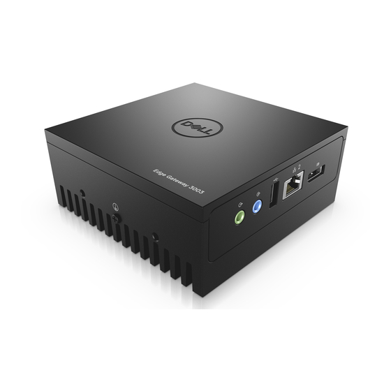
Page 9: Right View
Function Indicator Color Control Status On (Green): High-speed connection (100 Mbps) On (Amber): Low-speed connection (10 Mbps) Activity Green Driver (LAN) Off: No activity on link Blinking Green: LAN activity. The blink rate is related to packet density. NOTE: The power and system status light may operate differently during different boot-up scenarios, for example, when a USB script file is run during boot-up. - Page 10 Table 6. Right view—3003 Features Audio line-out (GREEN) Connect audio-output devices such as speakers and amplifiers. Audio line-in (BLUE) Connect recording or playback devices. USB 2.0 port Connect a USB enabled device. Provides data transfer speeds up to 480 Mbps. Ethernet port two (Non-PoE) Connect an Ethernet (RJ45) cable for network access.
-
Page 11: Installing Your Edge Gateway
10 percent of the input DC voltage. WARNING: When installing the Edge Gateway 3003, use a cable appropriate for the load currents: 3-core cable rated 5 A at 90°C (194°F) minimum, which conform to either IEC 60227 or IEC 60245. The system accepts cables from 0.8 mm to 2 mm. The maximum operating temperature of the Edge Gateway is 60⁰C (140°F). -
Page 12: Instructions D'installation Professionnelles
This product is designed for specific applications and needs to be installed by qualified personnel with RF and regulatory-related knowledge. The general user shall not attempt to install or change the setting. Installation location The product shall be installed at a location where the radiating antenna is kept 20 cm from nearby persons in its normal operation condition in order to meet regulatory RF exposure requirements. -
Page 13: Industry Canada Statement
This equipment complies with FCC radiation exposure limits for an uncontrolled environment. This equipment should be installed and operated with a minimum distance of 20 cm between the active transceiver and your body. NOTE: The country code selection is for a non-US model only and is not available to all US model. Per FCC regulation, all WiFi products marketed in the US must be fixed to US operation channels only. - Page 14 Connect an Ethernet cable to Ethernet port one. Connect the antennas depending on the configuration ordered (optional). NOTE: The antennas supported in the Edge Gateway vary depending on the configuration ordered. Table 7. Antennas supported in Edge Gateway 3003 Antennas supported Signals...
- Page 15 3003 Not applicable NOTE: Use only the supplied antennas or third-party antennas that meet the minimum specifications. NOTE: Depending on the configuration ordered, some of the antenna connectors may not be present or may be capped. NOTE: Mobile broadband antenna connector two is for LTE Auxiliary only; it does not support 3G. Insert the antenna into the connector.
- Page 16 Secure the antenna by tightening the rotating head of the connector until it firmly holds the antenna in the preferred position (upright or straight).
- Page 17 NOTE: Antenna images are for illustrative purposes only. Actual appearance may differ from the images provided. Connect all desired cables to the appropriate I/O ports on the Edge Gateway. Open the micro-SIM or micro-SD card access door. Insert a micro-SIM card into the top micro-SIM card slot and activate your mobile broadband service.
- Page 18 NOTE: Secondary enclosures are sold separately. 11. Connect the Edge Gateway to one of the following power sources: • DC-IN •...
-
Page 19: Activating Your Mobile Broadband Service
14. Access the BIOS by pressing F2 to enter the BIOS setup or F12 to enter the BIOS boot menu. Windows 10 IOT Enterprise LTSB 2016 Click Start → All Programs → Dell → Command Configure → Dell Command | Configure Wizard. Ubuntu Core 16 Use the dcc.cctk command to access the Dell Command | Configure application. - Page 20 NOTE: Ensure that the service provider has already activated the micro-SIM card before you use it in the Edge Gateway. Remove the screw to open the micro-SIM card access door. Insert a micro-SIM card into the top micro-SIM card slot. Replace the screw, and close the micro-SIM card access door.
-
Page 21: Mounting Your Edge Gateway
Example (Verizon): network-manager.nmcli con up VZ_GSMDEMO Example (AT&T): network-manager.nmcli con up ATT_GSMDEMO Example (3G): network-manager.nmcli con up 3G_GSMDEMO To disconnect from the mobile network: Command line: network-manager.nmcli con down <connection-name> Example (Verizon): network-manager.nmcli con down VZ_GSMDEMO Example (AT&T): network-manager.nmcli con down ATT_GSMDEMO Example (3G): network-manager.nmcli con down 3G_GSMDEMO Mounting your Edge Gateway... - Page 22 NOTE: The mounting brackets are shipped with only those screws that are required for securing the mounting brackets to the Edge Gateway. Secure the standard-mount bracket to the back of the Edge Gateway using the four M4x4.5 screws. NOTE: Torque the screws at 8±0.5 kilograms-centimeter (17.64±1.1 pounds-inch).
- Page 23 Place the Edge Gateway against the wall, and align the holes in the standard-mount bracket with the holes on the wall. Screw holes on the bracket have a diameter of 3 mm (0.12 in).
- Page 24 Place the standard-mount bracket on the wall, and using the holes above the screw holes on the bracket, mark the positions to drill the four holes.
- Page 25 Drill four holes in the wall as marked. Insert and tighten four screws (not supplied) to the wall. NOTE: Purchase screws that fit the diameter of the screw holes.
- Page 26 Align the screw holes on the standard-mount bracket with the screws and place the Edge Gateway onto the wall.
- Page 27 Tighten the screws to secure the assembly to the wall.
-
Page 28: Mounting The Edge Gateway Using Quick-Mount Bracket
Mounting the Edge Gateway using quick-mount bracket The quick-mount bracket is a combination of the standard-mount bracket and the DIN-rail bracket. It enables you to easily mount and demount the Edge Gateway. NOTE: The mounting brackets are shipped with only those screws required for securing the mounting brackets to the Edge Gateway. Mounting dimensions... - Page 29 Mounting instructions Place the standard-mount bracket on the wall, and using the holes above the screw holes on the bracket, mark the positions to drill the four holes.
- Page 30 Drill four holes in the wall as marked. Insert and tighten four screws (not supplied) to the wall. NOTE: Purchase screws that fit the diameter of the screw holes.
- Page 31 Align the screw holes on the standard-mount bracket with the screws on the wall, letting the bracket hang on the screws.
- Page 32 Tighten the screws to secure the assembly to the wall.
- Page 33 Align the screw holes on the DIN-rail bracket with the screw holes at the back of the Edge Gateway. Place the two M4x7 screws on the DIN-rail bracket and secure it to the Edge Gateway.
- Page 34 Place the Edge Gateway on the standard mount at an angle, and then pull the Edge Gateway down to compress the springs at the top of the DIN-rail bracket.
- Page 35 Push the Edge Gateway towards the DIN-rail to secure it on the standard-mount bracket.
-
Page 36: Attaching The Cable Control Bars To The Standard-Mount Bracket
NOTE: For more information about demounting the DIN-rail, see Demounting DIN rail. Attaching the cable control bars to the standard-mount bracket Mount the Edge Gateway on the wall using the standard-mount bracket quick-mount bracket. Place the cable control bar on the mounting bracket and secure it to the notch. CAUTION: Use the top cable control bar only with coaxial cable connections. - Page 37 Connect the cables to the Edge Gateway. Loop the cable lock (not supplied) to secure each cable to the cable control bar.
-
Page 38: Mounting The Edge Gateway On A Din Rail Using The Din-Rail Bracket
Mounting the Edge Gateway on a DIN rail using the DIN-rail bracket NOTE: The DIN-rail bracket includes the screws that are required for securing the bracket to the Edge Gateway. Align the screw holes on the DIN-rail bracket with the screw holes at back of the Edge Gateway. Place the two M4x7 screws on the DIN-rail bracket and secure it to the Edge Gateway. - Page 39 Secure the DIN-rail mounting bracket to the Edge Gateway using the two M4x7 screws provided. NOTE: Torque the screws at 8±0.5 kilograms-centimeter (17.64±1.1 pounds-inch) on the DIN-rail mounting bracket.
- Page 40 Place the Edge Gateway on the DIN rail at an angle, and then pull the Edge Gateway down to compress the springs at the top of the DIN-rail mounting bracket. Push the Edge Gateway towards the DIN-rail to secure the lower clip of the bracket onto the DIN rail. NOTE: For more information about demounting the DIN-rail, see Demounting DIN rail.
-
Page 41: Mounting The Edge Gateway Using The Perpendicular Mount
Mounting the Edge Gateway using the perpendicular mount NOTE: The perpendicular mount is designed for mounting in a DIN-rail only. NOTE: An open space of 63.50 mm (2.50 in) around the Edge Gateway is recommended for optimal air circulation. Ensure that the environmental temperature in which the Edge Gateway is installed does not exceed the operating temperature of the Edge Gateway. - Page 42 Align the screw holes on the DIN-rail mount bracket with the screw holes on the perpendicular-mount bracket, and tighten the two screws. NOTE: Torque the screws at 8±0.5 kilograms-centimeter (17.64±1.1 pounds-inch).
- Page 43 Place the Edge Gateway on the DIN rail at an angle and push the Edge Gateway down to compress the springs on the DIN-rail mount brackets. Push the Edge Gateway towards the DIN-rail to secure the lower clip of the bracket onto the DIN rail.
-
Page 44: Mounting The Edge Gateway Using A Vesa Mount
Secure the Edge Gateway on the DIN rail. Mounting the Edge Gateway using a VESA mount The Edge Gateway can be mounted on a standard VESA mount (75 mm x 75 mm). NOTE: The VESA mount option is sold separately. For VESA mounting instructions, see the documentation that is shipped with the VESA mount. -
Page 46: Setting Up The Zigbee Dongle
Setting up the ZigBee dongle CAUTION: Do not connect the ZigBee dongle if the Edge Gateway is installed inside the enclosure. Power off your Edge Gateway. Connect the ZigBee dongle to any external USB port on your Edge Gateway. Power on your Edge Gateway and complete the setup. NOTE: For more information about the ZigBee development, see www.silabs.com. -
Page 47: Setting Up The Operating System
Setting up the operating system CAUTION: To prevent operating system corruption from sudden power loss, use the operating system to gracefully shut down the Edge Gateway. The Edge Gateway is shipped with one of the following operating systems: • Windows 10 IoT Enterprise LTSB 2016 •... -
Page 48: Restoring Windows 10 Iot Enterprise Ltsb 2016
Windows 10 IOT Enterprise LTSB 2016 basic functions BIOS update Download BIOS updates for the Edge Gateway from www.dell.com/support. The download includes an executable file that may be run from the local machine. For more information about updating the BIOS, see Accessing and updating the BIOS. -
Page 49: Ubuntu Core 16
TPM support Windows 10 IoT Enterprise LTSB 2016 supports TPM 2.0. For more information about TPM resources, see technet.microsoft.com/en-us/ library/cc749022. System shutdown and restart Click Start → Power, and then click Restart or Shutdown to restart or shutdown the Edge Gateway, respectively. LAN and WLAN network configuration In the Search box, type Settings and open the Settings window. -
Page 50: Boot Up And Log In - Static Ip System Configuration
Boot up and log in – Static IP system configuration This allows you to connect your Edge Gateway through a host computer, which must be on the same subnet. NOTE: The static IP address of Ethernet port two on the Edge Gateway is set to these values at the factory: •... -
Page 51: Network Communication Interfaces
Rebooting the System Run the command: admin@localhost:$ sudo reboot Returns: System reboot successfully Root user credential Run the command: admin@localhost:$ sudo su - Returns: $ admin@localhost:~# sudo su – $ root@localhost:~# Identifying the System Service Tag Run the command: admin@localhost:$ cat /sys/class/dmi/id/product_serial The system tag is printed. - Page 52 • <ssidname> = iotisvlab, where ssid is the name of the access point. • <name> = testwifi, where name is the connection name, which is basically a connection identifier. • <keytype> = wpa-psk, where keytype is the WLAN key management security type being used. •...
- Page 53 Stop scanning after the Bluetooth keyboard is found. $ scan off Pair Bluetooth devices. $ pair <MAC address of Bluetooth keyboard> Enter PIN code on the Bluetooth keyboard, if required. Trust the Bluetooth keyboard. $ trust <MAC address of Bluetooth keyboard> Connect to the Bluetooth keyboard.
-
Page 54: Security
– Option 2: Restoring during system POST – Option 3: Restoring from boot menu (Edge Gateway 3003 only) Option 1: Restoring from the operating system CAUTION: These steps will delete all the data on your Edge Gateway Connect the Edge Gateway remotely or through a KVM session. - Page 55 Once installation is complete, a login screen is displayed. NOTE: On the Edge Gateway 3003, the login screen is displayed only if the display port is connected a monitor. At the login screen, enter the default user name and password: admin.
-
Page 56: Flashing A New Os Image
Service Tag of the Edge Gateway • A Windows computer with administrator rights and at least 8 GB of available storage space to download the Dell ISO recovery image • A blank USB flash drive with at least 8 GB of storage space. These steps delete all data on the USB flash drive. - Page 57 Click Yes in the User Account Control prompt. Connect the USB flash drive to the computer. Click Browse and navigate to the location where the Dell ISO recovery image file is saved. Select the Dell ISO recovery image file and click Open.
-
Page 58: Accessing And Updating Bios
Use Dell Command | Configure (DCC) to access BIOS settings Dell Command | Configure (DCC) is a factory-installed application in the Edge Gateway that helps to configure the BIOS settings. It consists of a Command Line Interface (CLI) to configure various BIOS features. For more information about DCC, see www.dell.com/... -
Page 59: Using The Usb Invocation Script
Flashing the BIOS from a USB flash drive Prerequisites • BIOS file. Download the file from www.dell.com/support. • A blank USB 2.0 or 3.0 USB flash drive with at least 4 GB of storage space. Follow these steps to update the BIOS: Power off the Edge Gateway. -
Page 60: Dell Command | Configure (Dcc)
Connect and login to the Edge Gateway. NOTE: Connect and login to the Edge Gateway with one these options: • Direct system configuration (only for Edge Gateway 3003) • Static IP configuration (only for Edge Gateway 3002 and 3003) Check the current BIOS details. -
Page 61: Default Bios Settings
Default BIOS settings General (BIOS level 1) Table 9. General (BIOS level 1) BIOS level 2 BIOS level 3 Item Default value System Information BIOS Version Not applicable System Information Service Tag Not applicable Asset Tag Not applicable Ownership Tag Not applicable Manufacturing Date Not applicable... -
Page 62: System Configuration (Bios Level 1)
BIOS level 2 BIOS level 3 Item Default value Time [HH:MM:SS A/P] Not applicable System configuration (BIOS level 1) Table 10. System configuration (BIOS level 1) BIOS level 2 BIOS level 3 Item Default value Integrated NIC Integrated NIC Enable UEFI Network Stack Enabled [Enable/Disable] [Disabled, Enabled, Enabled w/... -
Page 63: Secure Boot (Bios Level 1)
BIOS level 2 BIOS level 3 Item Default value Password Bypass Password Bypass [Disabled/Reboot Bypass] Disabled Password Change Password Change Allow Non-Admin Password Enabled Changes [Enable/Disable] UEFI Capsule Firmware Updates UEFI Capsule Firmware Updates Enable UEFI Capsule Firmware Enabled Updates [Enable/Disable] TPM 2.0 Security TPM 2.0 Security TPM 2.0 Security [Enable/... -
Page 64: Power Management (Bios Level 1)
Power management (BIOS level 1) Table 14. Power management (BIOS level 1) BIOS level 2 BIOS level 3 Item Default value Auto On Time Auto On Time Time Selection: [HH:MM A/P ] 12:00AM Auto On Time (if Wake Period =0) Value Selection: [0-254] Auto- Wake Period (0-254 minutes) Day Selection: [Disabled/Every... -
Page 65: System Logs (Bios Level 1)
BIOS level 2 BIOS level 3 Item Default value SERR Messages SERR Messages Enable SERR Messages [Enable/ Enabled Disable] BIOS Downgrade BIOS Downgrade Allow BIOS Downgrade [Enable/ Enabled Disable] Data Wipe Data Wipe Wipe on Next Boot [Enable/ Disabled Disable] BIOS Recovery BIOS Recovery BIOS Recovery from Hard Drive... -
Page 66: References
Dell Command | Configure Reference Guide Dell Command | Monitor User's Guide • Dell Command | PowerShell Provider User's Guide • For more information on using Dell Data Protection | Encryption see the documentation for the software at www.dell.com/support/ manuals. -
Page 67: Appendix
Appendix Antenna specifications The Edge Gateway is a professionally installed equipment. The Radio Frequency output power does not exceed the maximum limit allowed in the country of operation. CAUTION: Unauthorized antennas, modifications, or attachments may damage the device and potentially violate international regulations. -
Page 68: De-Mounting From Din-Rail Bracket
De-mounting from DIN-rail bracket Pull the Edge Gateway down to release from DIN-rail bracket. Lift the Edge Gateway bracket off the DIN rail. Connecting to the Edge Gateway Windows 10 IoT Enterprise LTSB 2016 Boot up and login – Direct system configuration Connect a monitor, keyboard and mouse to the Edge Gateway before you login. -
Page 69: Ubuntu Core 16
Secure a crossover network cable between Ethernet port two on the Edge Gateway and the configured Ethernet port on the computer. On the Windows computer, launch Remote Desktop Connection. Connect to the Edge Gateway using the IP address 192.168.2.1. The default username and password are both admin. Ubuntu Core 16 Boot up and log in –... -
Page 70: System Configuration (Bios Level 1)
BIOS level 2 BIOS level 3 Item Default value Memory Available Not applicable Memory Speed Not applicable Memory Channel Mode Not applicable Memory Technology Not applicable Processor Information Processor Type Not applicable Core Count Not applicable Processor ID Not applicable Current Clock Speed Not applicable Minimum Clock Speed... -
Page 71: Security (Bios Level 1)
BIOS level 2 BIOS level 3 Item Default value Enable USB Port1 [Enable/ Enabled Disable] Enable USB Port2 [Enable/ Enabled Disable] Audio Enable Audio [Enable/Disable] Enabled Miscellaneous Devices Enable WWAN [Enable/Disable] Enabled Enable WLAN/Bluetooth Enabled [Enable/Disable] Enable Dedicated GPS Radio Enabled [Enable/Disable] Enable MEMs Sensor [Enable/... -
Page 72: Secure Boot (Bios Level 1)
BIOS level 2 BIOS level 3 Item Default value Key Storage Enable [Enable/ Enabled Disable] SHA-256 [Enable/Disable] Enabled Clear [Enable/Disable] Disabled Computrace(R) Computrace(R) Deactivate/Disable/Activate Deactivate Chassis Intrusion Chassis Intrusion [Disable/Enable/On-Silent] Disable CPU XD Support CPU XD Support Enable CPU XD Support [Enable/ Enabled Disable] Admin Setup Lockout... -
Page 73: Post Behavior (Bios Level 1)
POST behavior (BIOS level 1) Table 28. POST behavior (BIOS level 1) BIOS level 2 BIOS level 3 Item Default value Keyboard Errors Numlock LED Enable Numlock LED [Enable/ Enabled Disable] Keyboard Errors Keyboard Errors Enable Keyboard Error Detection Enabled [Enable/Disable] Fastboot Fastboot...